Table of Contents
Advertisement
Advertisement
Table of Contents

Related Manuals for JETStream TwinForce Series


Summary of Contents for JETStream TwinForce Series
- Page 1 OPERATION MANUAL TwinForce™ Series Waterblast Unit...
- Page 2 Visual Safety System...
- Page 3 Jetstream of Houston, LLP or its authorized agent. Permitted copies must carry the same proprietary and copyright notices as were affixed to the original. Under the law, copying includes translations, whole or in part, into another language.
- Page 4 Nothing contained in this warranty shall make Jetstream liable for loss, injury, or damage of any kind to any person or entity resulting from any defect or failure in the machine or part.
-
Page 5: Table Of Contents
TwinForce™ Series Waterblast Unit TABLE OF CONTENTS WATERBLAST SAFETY ..................................................1 Recognizing Safety Information ..........................................1 Understanding Signal Words ..........................................1 Waterblast Safety Manual ...............................................1 Understanding Safety Decals ............................................. 2 General Safety Precautions ............................................4 Read Instructions ................................................. 4 Inspect Equipment ..............................................4 Check Pressure Ratings ............................................ - Page 6 Rear Lights and Reflectors ........................................... 17 Trailer Breakaway System ............................................18 Activating the System............................................. 18 CONTROL PANEL ....................................................19 Jetstream Connections ..............................................20 Jetstream 3000/3600/4200Bareshaft Pump InstallationGuidelines ........................21 Models ....................................................21 Water Supply ................................................... 21 Pulsation .................................................... 21 Lubrication ..................................................22 Jetstream 5200Bareshaft Pump InstallationGuidelines ..............................
- Page 7 TwinForce™ Series Waterblast Unit MAINTENANCE ....................................................35 Unit Maintenance ................................................35 Daily ....................................................... 35 50 Hours ..................................................... 35 100 Hours ................................................... 35 500 Hours ..................................................35 Winterizing The Unit ................................................ 36 Trailer Maintenance ................................................. 38 Tires .......................................................38 Wheel Bearings ................................................38 Lug Nuts .....................................................38 Axles ......................................................
- Page 8 Operation Manual Crankshaft ..................................................88 TROUBLESHOOTING ..................................................93 TRAINING ......................................................95 Safety Training ..................................................95 New Start-up Training ..............................................95 FS Solutions Training ..............................................95 Additional Training Opportunities ........................................95 APPENDIX A: TECHNICAL SPECIFICATIONS ......................................A-1 General Unit Information ............................................A-1 APPENDIX B: LONG TERM STORAGE PROCEDURE ....................................B-1 INDEX ......................................................INDEX-1 Scan or click the QR Code for...
-
Page 9: Waterblast Safety
Recognizing Safety Information Attention indicates installation, operation, or maintenance information which is important One of Jetstream’s ongoing endeavors is to but is not considered a hazard. minimize or elminate the risk of injury to the product user. Jetstream has taken every ef-... -
Page 10: Understanding Safety Decals
The following illustrations show common locations for safety decals. Decals and their locations may vary for different units. Always be familiar with the location and content of all safety decals on any Jetstream unit. Figure 1: Example of Safety Decals... - Page 11 TwinForce™ Series Waterblast Unit...
-
Page 12: General Safety Precautions
Tape fragments may enter the system’s Further instructions for safe operation are water stream and clog the nozzle’s orifices. located in the Jetstream Safety Manual. Read Apply a coat of anti-seize compound over the this manual before operating the equipment. -
Page 13: Purge The System
Test the System erly trained to maintain this equipment. Train- ing is available through Jetstream and can be ® With the nozzle installed, operate the pump at requested from the Jetstream website (www. -
Page 14: Trailer Safety
Operation Manual Check Brake Systems Trailer Safety The Jetstream trailer is equipped with electric brakes. Before towing the trailer, verify that the Tires and Rims trailer brakes are working properly. An inflated tire and rim can be very dangerous Breakaway System if improperly used, serviced or maintained. -
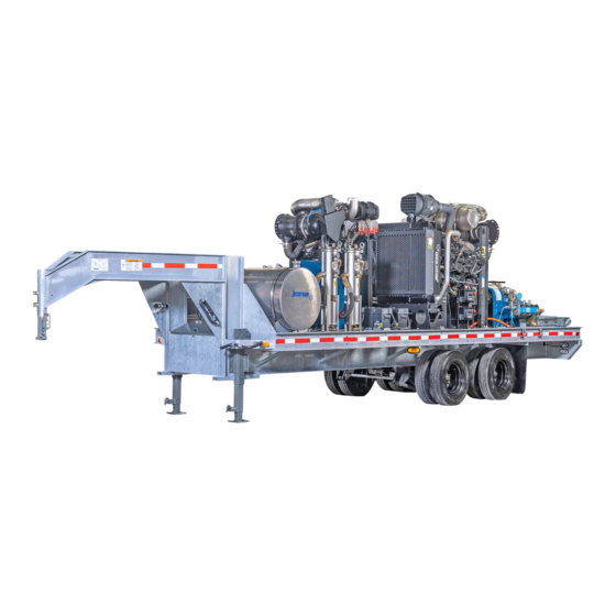
Page 15: Component Identification
Belt Drive Water Filters Fuel Tank Pump Figure 8: TwinForce Series Waterblast Unit Engine to pressurize the source water into high pres- sure output. The pump is separated into two The engine is the source of power to drive sections, the power end and the fluid end. -
Page 16: Manifold
Operation Manual Rupture Discs Pressure Gauge Hydro-Throttle Switch Water Lubrication Manifold System Drain Valve Manifold Figure 9: Pump Components Manifold Drain Valve charge pump into the first filter and then the second filter in line. A ball valve is fitted to the The manifold drain valve allows the manifold inlet side of the filter after the charge pump. -
Page 17: Hydro-Throttle Switch (Optional)
TwinForce™ Series Waterblast Unit Bypass Valve Supply Couplings Discharge Fitting Figure 11: Pump Components (continued) Hydro-Throttle Switch (Optional) low pressure. Turning the knob allows the op- erator to adjust pressure during operation and The hydro-throttle switch senses the pressure relieve pressure when not waterblasting. within the pump and allows the engine to idle The bypass valve controls pressure by allowing when the operator is not blasting. -
Page 18: Discharge Fitting
Operation Manual when operating one or more shut-in devices. When a gun or other device is disengaged, the regulator automatically adjusts to shift the excess flow to a low pressure outlet while maintaining system pressure. Because shut-in systems maintain constant system pressure, the hydro-throttle does not function in these applications. -
Page 19: Water Inlet
If Figure 13: Water Inlet bypass drain water needs to be routed to a dif- ferent location, contact Jetstream engineering for assistance. CAUTION If a bypass discharge hose is used, the hose must be properly sized to prevent excessive backpressure. -
Page 20: Fuel System
Operation Manual Fuel System The unit houses two 125 gallon fuel tanks (Figure 15) with mechanical float valve gauges. Fuel sender mounting flange is standard op- tion. The tanks are used SEPARATELY and each has to be filled separately for use with its as- sociated engine. -
Page 21: Charge Pump (40K Units)
A serial number plate displays the model and serial number of the unit. Always refer to this Figure 18: Fluid End Rating Plate serial number when contacting Jetstream for parts or service. An emissions plate displays the emissions certification as well as the date of manufac-... - Page 22 Operation Manual...
-
Page 23: Trailer Units
TwinForce™ Series Waterblast Unit TRAILER UNITS Twin Force unit components are mounted to a deck over gooseneck trailer. GVWR and Axle Fire Extinguisher information & VIN can be found on the tongue, on the inside or outside face of the member. Trailer Components Fire Extinguisher (Optional) A multi-purpose dry chemical fire extinguisher... -
Page 24: Electrical Connector
Operation Manual Electrical Connector The 7-pin electrical connector (Figure 22) connects the tow vehicle’s electrical system (lighting, charging, braking) to the trailer. Electrical Connector Note: The center pin on the electrical con- nector is not used. Ground Cable (Optional) Attach the grounding cable (Figure 23) to the structure being cleaned to prevent sparks cre- ated by static electricity. -
Page 25: Lighting And Reflectors
TwinForce™ Series Waterblast Unit Lighting And Reflectors Rear Lights and Reflectors The trailer is equipped with a row of rear mark- Front and Side Lights and Reflectors ers lights (Figure 25) required for trailers over 80 in. (203 cm) wide. The lights will illuminate The trailer is equipped with two front clearance when the tow vehicle has its lights turned on. -
Page 26: Trailer Breakaway System
Operation Manual Trailer Breakaway System The trailer is equipped with a breakaway system in the event that the trailer should come un- hitched from the tow vehicle. If this occurs, the breakaway system will apply the trailer brakes to bring the trailer to a stop. Battery The breakaway system includes a battery (Fig- ure 26) and a breakaway switch (Figure 27). -
Page 27: Control Panel
TwinForce™ Series Waterblast Unit CONTROL PANEL Twin Force units come equipped with a total of 4 control panels. The associated panels are ei- ther marked with a “1” or a “2” (Figure 28). Two control panels are able to control and monitor a single engine, although only one of each pair is able to start with key. -
Page 28: Jetstream Connections
Each end of the tether cable connecting two panels for control of the same engine is iden- tified as “Near Side” or “Far Side” (Figure 29). This designates which panel that particular end should connect to. Figure 29: Jetstream Wiring Connections. -
Page 29: Jetstream 3000/3600/4200Bareshaft Pump Installationguidelines
The inlet supply hose should be 3” ID if NOTE: This following pages contain gravity fed and 2” ID if pressure fed. Jetstream instailation guidelines for all of recommends oilfield suction hose as it has Jetstream’s bareshaft pumps. -
Page 30: Lubrication
The powerend oil has a recommended maxi- mum temperature of 190°F and can be com- fortably run in most environments. Extremely hot or cold envi- ronments (i.e. Middle East, Canada) may require oil cooler or synthetic oil. Contact Jetstream Engineering for assistance. -
Page 31: Jetstream 5200Bareshaft Pump Installationguidelines
TwinForce™ Series Waterblast Unit Jetstream 5200 Bareshaft Pump Installation Guidelines All of the previous requirements for the 4200 are the same for 5200 except as noted below: 5200 series 400 hp max 518 rpm max Water Supply The 5200 pump cannot be gravity fed and re- quires 40-50 psi suction water pressure at full pump speed to operate. -
Page 32: Technical Notes
Technical Notes *** Driver selection and coupling selection re- quires engineering analysis of torsional loads and vibra- tions (TVA). Jetstream can supply the mass- elastic data for the pump but it is customer’s responsibil- ity to perform TVA of the system. Coupling failure, engine damage, and powerend damage can result from incor- rect coupling selection. -
Page 33: Operation
3. Remove all on board packages. 4. Inspect the unit and report any damage to your Jetstream representative. 5. Remove the pump wrench from the rod Figure 31: Pump Wrench Removal. box (Figure 31). -
Page 34: Recommended Equipment
6. Check the oil level in the PTO. than replacing a coupling. The manifold would need to be shipped back to Jetstream for repair or 7. Inspect the filter bags. Inspect the sec- replacement. -
Page 35: Starting The Unit
TwinForce™ Series Waterblast Unit 12. Install the discharge hose onto the fitting 6. Start the engine by rotating the key on the manifold along with a hose safety switch to the RUN position. Wait for the check. “Engine Ready to Start” message to ap- pear on the panel. -
Page 36: Flushing The System
Operation Manual the clutch. Flushing the System 10. Turn the bypass valve clockwise to in- With the engine at idle, warming to operating crease flow through the discharge temperature, flush the system of any debris. device(s). Allow the control gun to flush Flushing the system prevents any debris from for about 30 seconds. -
Page 37: Checking The Water Lubrication System
TwinForce™ Series Waterblast Unit 11. Reduce the discharge flow by fully open- ing the bypass valve. 12. With the engine at idle speed, disengage the clutch. 13. The nozzles can now be installed on the Lubrication Line Stuffing Box discharge device(s). 14. -
Page 38: Raising System Pressure
Operation Manual pump fluid ends are entering. Slowly turn 5. Once properly adjusted, system pressure the bypass valve clockwise to start clos- can be raised for waterblasting. ing the bypass and build pressure. 6. 5200 pump differences: The plumbing 3. Slowly increase pressure by increasing arrangement is slightly different on the engine rpm by 300 rpm on each engine at 5200 power end. -
Page 39: Breaking In New Packing
TwinForce™ Series Waterblast Unit Breaking in New Packing Using the Hydro-Throttle (Dump System Only) ATTENTION The hydro-throttle allows the operator to set an operating speed This procedure is only applicable for 15K and 20K molded packing. It is not required for plastic for the engine to cycle between as packing. -
Page 40: Monitoring Weep Holes
Operation Manual Monitoring Weep Holes Weep holes are manufactured into the manifold Face Seal weep hole to alert the operator when seals have failed. If a seal fails, the water will leak from its associated leakage hole. Uni-valve There are two types of weep holes, the high weep hole pressure face seal weep holes that are rectangu- lar slots (Figure 40) and the low pressure uni-... -
Page 41: Pressure Controls
TwinForce™ Series Waterblast Unit Pressure Controls When the combined output of both pumps is required, the pressure controls at the rear of the trailer are used (Figure 43). There is a bypass pressure control for both 15K Max and 20K Max pressure that allow pressure control for the flow incoming from two hoses. - Page 42 Operation Manual...
-
Page 43: Maintenance
TwinForce™ Series Waterblast Unit MAINTENANCE 50 Hours Check Pump Drive Belt Tension - Ensure Unit Maintenance the belts are properly tensioned per the tension decal under the belt cover. Refer to “Checking Belt Tension” on page 74. Note: Refer to the OEM manual for main- 2. -
Page 44: Winterizing The Unit
Operation Manual 3. Belt Inspection - Inspect the belts for cracks, damage, glazing or any other defect. Replace as necessary. Replace the belts as a set and adjust the new belts as outlined in “Adjusting Belt Tension” on page 75. Funnel Assembly 4. - Page 45 TwinForce™ Series Waterblast Unit 9. Start the engine. 10. With the engine idling, gently feather the clutch by applying light pressure to the clutch handle in the engagement direc- tion. Watch the plungers move back and forth slowly until anti-freeze is dis- charged from the manifold port as shown in (Figure 46).
-
Page 46: Trailer Maintenance
9-15K Axle Complete Service Manual Lug Nuts WARNING All wheel lug nuts supplied with Jetstream Wa- terblast Trailer Units utilize a M22-1.5 thread. Failure to grease or properly seal wheel bearings Replacement lug nuts must match the wheel could lead to bearing failure resulting in wheel loss studs supplied with the unit. -
Page 47: Axles
Battery derslung configuration and each has a gross axle weight rating of 15,000lb (6804 kg) If a problem with an axle is suspect, contact your Jetstream representative. Trailer Breakaway System System Check Figure 50: Breakaway System Kit Location. Disconnect the trailer connector from the tow vehicle. - Page 48 Operation Manual...
-
Page 49: Water And Filtration
Substance Maximum Allowed (mg/L) Silica The quality of water that is supplied to your Calcium Jetstream pump can have a direct impact Magnesium on performance. Items like dissolved solids Iron and pH values out of the allowable range can, either by themselves, or together with other... -
Page 50: Filter Inspection
Operation Manual Filter Inspection Loosen the 3 eye bolts (Figure 52) secur- ing the filter housing cover and swing the lid open. 2. Lift the filter bags (Figure 53) from the filter housing and inspect for debris. Replace as necessary. Cover ATTENTION Figure 52: Filter Housing Cover... -
Page 51: Filter Cartridge Replacement
7 to 10 psi (0.48 to 0.69 bar). If the switch doesn’t close within the 7 to 10 psi (0.48 to 0.69 bar) range, it may need to be adjusted. Contact Jetstream for switch adjustment instructions. Uni-Valve Life... - Page 52 Operation Manual...
-
Page 53: Pressure Conversion
Supply Coupling WARNING When switching to higher operating pressures, it is necessary that all equipment be properly pressure rated. Refer to the Jetstream Safety Manual for specific guidelines for hoses, fittings, etc. Figure 58: Line Removal. Converting a Pump Use the following procedure to convert a pump Cover to a different pressure. - Page 54 62) into the two open holes to allow for easier installation of the new manifold. Figure 60: Hinge Rod, Trunnions, and Cotter Pin. Note: Manifold mounting studs can be purchased from Jetstream. (p/n 54261) Manifold 9. Continue removing the remaining mani- Bolts fold bolts.
- Page 55 TwinForce™ Series Waterblast Unit 10. Once all of the bolts are removed, lift the manifold off the pump (Figure 63). CAUTION Use two people to lift the manifold. The Manifold is heavy and failure to use two people may cause serious injury.
- Page 56 Operation Manual 13. Pull each stuffing box from the pump case (Figure 66). 14. Clean the stuffing box bore thoroughly and apply petroleum jelly or Anti-Seize to the bores. ATTENTION Apply petroleum jelly or Anti-Seize to each stuffing box bore when installing stuffing boxes to help prevent corrosion and extend pump life.
- Page 57 TwinForce™ Series Waterblast Unit 18. Apply Teflon tape to the threads of the lubrication line fittings (Figure 69). Install the fittings onto the stuffing boxes. Lubrication Fitting 19. Apply a light coating of petroleum jelly or Anti-Seize to the mounting face of the power end.
- Page 58 Operation Manual c. To install the hinge rod (Figure 72), it will be necessary to either lift the manifold or use a screwdriver to flex the rod while simultaneously tapping the end with a hammer to get the rod through the second set of trunnions. Check for correct alignment and free rotation of the manifold bolts.
- Page 59 TwinForce™ Series Waterblast Unit 25. Connect the water lubrication lines (Figure 75) to the fittings on the stuffing Cover boxes. 26. Connect the supply coupling (Figure 76) Lubrication and the bypass hose to the manifold. Lines 27. Place the hydro-throttle switch and housing (Figure 77) into position and install the two bolts that secure it.
-
Page 60: 40K Hose Connections
Operation Manual 40K Hose Connections Filter Inlet Remove the supply hose (Figure 78) (sup- ply from charge pump) from the suction elbow fitting on the 15K/20K manifold. 2. Install the 40K manifold as outlined ear- Secondary lier in this chapter. Filter 3. -
Page 61: Service
TwinForce™ Series Waterblast Unit SERVICE Fluid End Checking Manifold Bolt Torque Figure 81: Tightening Sequence. Verify the head bolts are properly tightened. Check the bolt torque in a crisscross sequence starting with the center bolts (Figure 81). Proper torque is 350 ft.-lb. (470 N·m) which can be achieved with a few hammer strikes on the pump wrench. -
Page 62: Rupture Disc Inspection
Figure 83: Housing/Cap Removal (15K Manifold Shown). Installation of rupture discs with a burst pressure no greater than 1.4 times the working pressure is required by Jetstream for warranty coverage on this pump. Rupture Disc 4. Install the upper housing back onto the assembly. - Page 63 TwinForce™ Series Waterblast Unit 6. Insert the rounded end of the pump wrench (Figure 86) into one of the holes in the gland nut and tap the top of the wrench sharply with a heavy hammer to loosen. When loose, unscrew the gland nut from the stuffing box by hand.
- Page 64 Operation Manual 10. Remove the plunger and guide bushing (Figure 89) from the gland nut and inspect. Note: The guide bushing may be stuck and require some force to remove. Use a tool in the cutout (Figure 90) to push the bushing out. Use caution to avoid damaging the Guide gland nut.
- Page 65 TwinForce™ Series Waterblast Unit Note: On 40K fluid ends, the brass sleeve (Figure 91) inside the stuffing box does not need to be removed unless the plunger shows evidence of rubbing on the sleeve. 11. Remove the O-ring (Figure 92) from the gland nut.
- Page 66 Operation Manual Installation Install a new O-ring (Figure 94) onto the gland nut. 2. Install the guide bushing (Figure 94) and plunger into the gland nut. 3. Place the new packing and guide bush- ing onto the plunger. Orient the packing Guide Bushing as shown in (Figure 91) for 15K/20K and...
- Page 67 TwinForce™ Series Waterblast Unit 5. Pull the plunger (Figure 96) back to meet the crosshead pony rod. If the packing is too tight to move the plunger by hand, the pump can be rotated by hand (via the belts) to move the pony rod to meet the plunger.
-
Page 68: Uni-Valve Service
Operation Manual Uni-Valve Service Cover Removal Relieve pressure from the pump, shut off Lubrication the engine and disengage the clutch. Lines 2. Turn off the water supply and drain the water tank. 3. Disconnect the bypass drain hose and the supply coupling from the manifold (Fig- ure 99). -
Page 69: 40K Face Seal Replacement
• 3600/4200 Series: 165 lb. (75 kg) • 3000 Series: 90 lb. (41 kg) Valves 7. Use two small pry bars (Jetstream p/n 70179) to pry the valve out of the manifold as shown in (Figure 103). 8. Remove the remaining valves. Refer to the... - Page 70 Operation Manual Installation Place the valve into position on the mani- fold. Using the palms of your hands, press the valve into the manifold as shown in (Figure 105). 2. Install the remaining valves. 3. Swing the manifold upward to install the bolts.
-
Page 71: 15K, 20K Uni-Valve Service
TwinForce™ Series Waterblast Unit 15K, 20K Uni-Valve Service Disassembly Remove the O-ring at each end of the O-Ring valve (Figure 109). Discard the O-rings. 2. Locate the slits in the two white backup rings and carefully remove the rings. Re- move the companion O-rings, as well (Fig- ure 110). - Page 72 Operation Manual 4. Remove the valve spring retainer and Spring Retainer valve spring (Figure 112). 5. Lift the assembly off of the suction valve Spring and set the suction valve aside. 6. Insert a small screwdriver under the dis- charge spring (Figure 113). Carefully rotate Suction Valve the screwdriver until the spring releases from the groove.
- Page 73 TwinForce™ Series Waterblast Unit O-Ring 6. O-Ring 11. Retaining Ring (3015 Valves Only) 2. Backup Ring 7. Backup Ring 12. Suction Valve Spring 3. O-Ring 8. O-Ring 13. Spring Retainer 4. Suction Valve 9. Discharge Valve 14. Retaining Ring 5. Discharge Valve Body 10.
- Page 74 Operation Manual Assembly Install the discharge valve onto the valve body. The shiny mating surface faces the holes on the valve body. Place the dis- Discharge charge spring into position on the valve Spring (Figure 115). 2. Lock the spring in its retaining groove. Use a screwdriver to push the spring in place.
-
Page 75: 40K Uni-Valve Service
TwinForce™ Series Waterblast Unit 40K Uni-Valve Service Disassembly Use a small screwdriver to remove the two black O-rings from the valve (Figure 118). 2. Use the screwdriver to remove the seal retaining ring. Insert the blade under the slit and rotate the ring out of the groove (Figure 119). - Page 76 Operation Manual 5. Press down on the valve spring retainer Keeper and slide the spring keepers out from the assembly (Figure 121). Spring 6. Remove the valve spring and valve spring retainer. 7. Remove the suction and discharge valves Spring (Figure 122).
- Page 77 TwinForce™ Series Waterblast Unit Assembly Install the discharge valve into the valve body (Figure 123). 2. Position the valve spring and valve spring retainer into place on the suction valve. Press down on the spring retainer to insert the keepers (Figure 124). 3.
- Page 78 Operation Manual Valve Inspection Inspect all seals and discard as neces- sary. 2. Inspect the valve components. Discard excessively pitted or otherwise damaged components (Figure 127). 3. For valves with minor wear or corrosion, recondition the valves as outlined in Valve Excessive Pitting Lapping.
-
Page 79: Bypass Valve Cartridge Replacement
TwinForce™ Series Waterblast Unit 6. Continue the lapping process until the desired sealing surface is achieved. 7. Repeat the lapping process for the dis- charge valve. 8. When completed, clean all metal parts Cartridge by submerging in a mineral spirits solu- Housing tion for a few minutes. -
Page 80: Power End
Operation Manual over slowly for 10-15 seconds. Disengage the Power End PTO. Check the oil-level at the site gauge. If the oil level is still visible in the gauge, there is sufficient oil in the crankcase to Checking Power End Oil Level run the pump. -
Page 81: Changing The Power End Oil
TwinForce™ Series Waterblast Unit Changing the Power End Oil With the engine off, remove the drain plug (Figure 136) from the oil drain valve lo- cated on the back of the power end case. 2. Place a container below the valve large enough to capture the oil. -
Page 82: Changing Pto Oil
Operation Manual Changing PTO Oil Place a container below the PTO large enough to capture the oil in the PTO case (26 oz) (0.77 L). Force 2. Remove the drain plug (Figure 135) and O-Ring allow the oil to fully drain from the case. 3. -
Page 83: Adjusting Belt Tension
TwinForce™ Series Waterblast Unit belt if necessary. Refer to “Adjusting Belt Tension”. Adjusting Belt Tension Pump Mounting Loosen the four pump mounting bolts Bolts (Figure 139). the bolts are located on each corner of the pump. Tensioner Nut 2. Adjust the tension by turning the tension nut . -
Page 84: Charge Pump
Operation Manual Charge Pump Removal Park the trailer on a hard, level surface and chock the wheels. For skid mounted units, lift the unit onto a hard, level surface and install cribbing under the unit for access to the charge pump. Mounting Nut 2. -
Page 85: Crosshead Pony Rod Seals
TwinForce™ Series Waterblast Unit 4. Install the charge pump drive belt. 5. If a hoist is available, attach a hoist and appropriate lifting apparatus to the belt guard. Lift the belt guard from the unit. The weight of the belt guard is approximately 70 lb (32 kg). - Page 86 Operation Manual 11. Install two 1/2”-13 UNC capscrews (Figure 148) into the seal plate. 12. It may be necessary to use a long pry bar Pry Bar with the power frame as a lever to pry the back of the bolts. The seal plate should pop out from its bore.
- Page 87 TwinForce™ Series Waterblast Unit 3. Place the green inboard seal into position on top of the outboard seal and orient the seal (Figure 151). Press the seal into the plate until it is flush with the face of the plate. Use caution to avoid damaging the seal.
-
Page 88: Rod Journal Bearings
Operation Manual Rod Journal Bearings Removal Belt Guard Drain the oil from the power end as out- lined in “Changing the Power End Oil” on page 73. 2. Once drained, remove the capscrews, Cap SCrew washers and lockwashers from the back plate (Figure 154). - Page 89 TwinForce™ Series Waterblast Unit 6. Remove the journal bearing from the rod cap and discard (Figure 157). 7. To access the inner journal bearing (Fig- ure 158), push the connecting rod away from the crankshaft. Slide the bearing from the rod. Journal Bearing Inspection Wipe the excess oil from the end cap...
- Page 90 Operation Manual 6. Measure the flattened plasti-gauge using the gauge wrapper (Figure 160). 7. If the thickness of the plasti-gauge exceeds 0.012 in. (0.31 mm), replace the bearings. If the bearings do not exceed the criteria, the bearings can be reused. Note: New part clearances are as fol- lows: •...
- Page 91 TwinForce™ Series Waterblast Unit 6. Pull the connecting rod (Figure 164) onto the crankshaft and place the rod cap into position aligned with the connecting rod. Ensure the stampings (Figure 165) on the cap and rod match. 7. Screw in the capscrews by hand and then Connecting Rod tighten to the proper torque: •...
-
Page 92: Crosshead And Connecting Rod Assembly
Operation Manual Note: New part clearances are as follows: Crosshead and Connecting Rod Assembly • Series 3000: 0.0030 in. (0.08 mm) - 0.0037 in. (0.09 mm) Removal • Series 3600/4200: 0.0040 in. (0.1 mm) - Remove the crankshaft from the pump as 0.0047 in. - Page 93 TwinForce™ Series Waterblast Unit Crosshead Inspection 8. Apply Loctite Red-271© onto the threads of the second backup set screw. Use a micrometer to measure the outer 9. Install the second set screw on top of the diameter of the crosshead in three places first set screw.
-
Page 94: Unx Pump
Operation Manual Installation Throttle Switch Place the crosshead/connecting rod Bypass Hose assemblies into position inside of the crankcase. 2. Install the crankshaft as outlined in “In- stallation” on page 89. UNx Pump Supply Hose Removal Drain the water tank. 2. Remove the bypass hose and supply hose (Figure 171). - Page 95 TwinForce™ Series Waterblast Unit Installation If shims were under the pump, place the shims in their proper location. 2. Apply an anti-seize compound to the four pump mount channels (Figure 174). 3. Attach a hoist and lifting apparatus to the pump as shown in (Figure 175).
-
Page 96: Crankshaft
Operation Manual Crankshaft 6. Pull the three connecting rod/crosshead assemblies towards the fluid end as far as possible. Removal 7. Remove the eight capscrews and washers Remove the pump from the unit. Refer to that secure the inboard side plate (Figure “UNx Pump”... - Page 97 • 3000 Series: 125 lb. (57 kg) • 3600/4200 Series: 325 lb. (147 kg) Outer Race 14. Remove the bearings from the crankshaft. Contact Jetstream for assistance with this task. Installation Heat the crankshaft bearings in a 250°F (121°C) oven for 20 minutes. Check the bearing color as they are heated.
- Page 98 Operation Manual 7. Place the three crosshead/connecting rod assemblies into place (Figure 183). Allow clearance for the crankshaft by pushing them towards the fluid end. 8. Install two threaded rods (1 in.-8NC x 8 in.) into the ends of the crankshaft to aid in Connecting Rod installation.
- Page 99 TwinForce™ Series Waterblast Unit 13. Mount a magnetic base dial indicator on the crankshaft with the indicator pin on Dial Indicator the inside edge of the rear opening, as shown in Figure 186. 14. With a firm, slow but not sudden pull in both directions the total end play should read within 0.001 inch (0.03 mm) - 0.004 inch (0.10 mm) tolerances.
- Page 100 Operation Manual...
-
Page 101: Troubleshooting
TwinForce™ Series Waterblast Unit TROUBLESHOOTING PROBLEM POSSIBLE CAUSE REMEDY Nozzle too small Replace nozzle High discharge Restriction in hose or lance Test hose/lance without nozzle pressure Inaccurate pressure gauge Replace gauge Nozzle too large Replace nozzle Nozzle worn Replace nozzle Insufficient water tank level Fill tank, unplug vent Inaccurate pressure gauge... - Page 102 Operation Manual PROBLEM POSSIBLE CAUSE REMEDY Needle valves not properly adjusted Adjust the needle valves Insufficient water Air in the system Open the manifold drain with pump on lubrication Plugged lines Remove debris from lubrication lines Leakage from pump manifold uni-valve Damaged valve seal Replace seals leakage holes...
-
Page 103: Training
Jet- tenance training. stream waterblast units with the knowledge For more information contact Jetstream. and support needed to feel familiar, confident and satisfied with Jetstream equipment and personnel. Additional Training Opportunities 1. Transportation... - Page 104 Operation Manual...
-
Page 105: Appendix A: Technical Specifications
The various plunger diameters The versatility of these Jetstream waterblast control the discharge volume. The stuffing units allows operators to modify the pump to boxes are matched to the plungers in most... - Page 106 Appendix A: Technical Specifications...
-
Page 107: Appendix B: Long Term Storage Procedure
TwinForce™ Series Waterblast Unit APPENDIX B: LONG TERM STORAGE PROCEDURE... - Page 108 Appendix B: Long-Term Storage Procedure...
-
Page 109: Index
Water Inlet 11 SERVICE 53 Water Lubrication System 8 Fluid End 53 CONTROL PANEL 19 15K, 20K Uni-Valve Service 63 Jetstream Connections 20 Assembly 66 Keyswitch Operation 20 Disassembly 63 40K Face Seal Replacement 61 Installation 62 40K Uni-Valve Service 67... - Page 110 Operation Manual Adjusting Belt Tension 75 Test The system 5 Changing PTO Oil 74 Tighten Connections 4 Changing the Power End Oil 73 Use The minimum Pressure Required 5 Charge Pump 76 Use Two Operators 4 Installation 76 Recognizing Safety Information 1 Removal 76 Understanding Signal Words 1 Checking Belt Tension 74...
- Page 111 WARNING: Breathing diesel engine exhaust exposes you to chemicals known to the State of California to cause cancer and birth defects or other reproductive harm. • Always start and operate the engine in a well-ventilated area. • If in an enclosed area, vent the exhaust to the outside. •...
- Page 112 P/N 69098 Federal Signal Corporation is listed on the NYSE by the symbol FSS. © 2022 Jetstream of Houston, LLC. All rights reserved. Specifications and equipment listed are subject to change without notice. Some photos are shown with optional equipment.
Need help?
Do you have a question about the TwinForce Series and is the answer not in the manual?
Questions and answers