Page 3
This manual is copyrighted with all rights reserved. Under copyright laws, this manual may not be copied in whole or in part or reproduced in any other media without the express written permission of Jetstream of Houston, LLP or its authorized agent. Permitted copies must carry the same proprietary and copyright notices as were affixed to the original.
Page 4
Jetstream in Houston, Jetstream FS Solutions Rental Center, the customer’s location, or at other locations approved by Jetstream. Labor is furnished only when the unit or part is returned to the factory or when travel and expenses are paid by the purchaser.
Page 6
500 Hours .................................19 1000 Hours ................................19 Winterizing The Pump ..............................20 WATER ....................................21 Water Quality Requirements ............................21 Fluid Compatibility with Jetstream Pumps................................21 Secondary Filter (40k Operation Only) ..........................22 Filter Cartridge Replacement ...........................23 Switch Adjustment ..............................23 Uni-Valve Life ................................23 PRESSURE CONVERSION ............................... 25 Converting a Pump ................................25...
Page 7
Bareshaft Pump TROUBLESHOOTING ................................ 69 TRAINING ................................... 71 Safety Training................................71 New Start-up Training ..............................71 FS Solutions Training ..............................71 Additional Training Opportunities...........................71 INDEX ....................................IND-1...
It provides guidelines and instruc- user. Jetstream has taken every effort to alert the tions for maintaining a safe work environ- user to potential safety risks through the use of cau-...
Further instructions for safe operation are located Apply a coat of anti-seize compound over the Teflon in the Jetstream Safety Manual. Read this manual sealant to prevent “galling” or seizing of threads. before operating the equipment.
Training is available through Jetstream and can be requested from the Jetstream ® website (www.waterblast.com) or FS Solutions rental centers. Following repairs or maintenance, operate the sys- tem at low pressure to test the system.
Bareshaft Pump COMPONENT IDENTIFICATION Before operating the unit it is necessary to fully understand each component and how it functions. Following is a brief description of the unit’s main components. Figure 1: Bareshaft Pump. Pump Manifold Drain Valve The UNx pump uses the power from the engine The manifold drain valve allows the manifold to be to pressurize the source water into high pressure flushed of contaminants prior to pump usage.
If a rupture disc should burst, there is no way to build pressure until the disc is Regulator Valve (Not Shown) replaced. Use only genuine Jetstream rupture discs For shut-in systems (where no low pressure water properly rated for the intended operating pressure.
Bareshaft Pump Bypass Valve Discharge Fitting Supply Couplings Figure 3: Pump Components (Continued). Supply Couplings The supply couplings provide a quick method for attaching the supply hose to the manifold. Secondary Filter (40K Units) A secondary filter (Figure 4) is mounted on top of the pump for use when operating at “40K”.
Models Positive displacement pumps create pulsation in the high pressure discharge line. For this reason, The Jetstream UNx bareshaft pump is available in it is extremely important to utilize flexible hoses three horsepower ranges and three pressure ranges (ie rubber, thermoplastic) in lieu of rigid piping to –...
Bareshaft Pump Jetstream 6000 Bareshaft Pump Installation Guidelines All of the previous requirements are the same for 6000 except as noted below: The 6000 powerend is internally geared and requires inline drive with flexible coupling ***. It is available in four different gear ratios to support diesel engine or electric motor input speeds.
*** Driver selection and coupling selection requires engineering analysis of torsional loads and vibra- tions (TVA). Jetstream can supply the mass- elastic data for the pump but it is customer’s responsibil- ity to perform TVA of the system. Coupling failure, engine damage, and powerend damage can result from incorrect coupling selection.
OPERATION Recommended Equipment Hose and Water Supply Requirements Jetstream equips the waterblast units with the com- ponents they recommend for safe operation. Those – The water supply hose inside diameter must components include: be large enough to supply 150% of the unit’s •...
Operation Manual Start-up Preparation 1. Inspect the filter bags. Inspect the secondary filter cartridge if operating at 40K. 2. Check the tightness of the gland nuts on each stuffing box. 3. Inspect all equipment. Ensure that every piece of equipment in the pressure circuit is properly rated for the intended operating pressure.
Bareshaft Pump 13. The nozzles can now be installed on the dis- Flushing the System charge device(s). 14. Before waterblasting, adjust the lubrication line With the engine at idle, warming to operating tem- needle valves, if equipped. Refer to “Checknig perature, flush the system of any debris.
Operation Manual Checking the Water Lubrica- tion System 1. Lift the rod box cover to view the water lubrica- tion system. Lubrication Line Stuffing Box WARNING There are moving parts inside the rod box that can cause serious injury. Use extreme cau- tion.
Bareshaft Pump Raising System Pressure ATTENTION Always blast with the bypass valve fully WARNING closed. This will ensure the most efficient oper- ation with all water being utilized. If less water volume is required, reduce the engine rpm to Before building pressure, contain the high pressure discharge hose.
Operation Manual Breaking in New Packing ATTENTION This procedure is only applicable for 15K and 20K molded packing. It is not required for plastic packing. New packing must be broken in to prevent damage and ensure optimal performance. Break-in should occur in three to four pressure increases over a 5 minute period.
Bareshaft Pump Monitoring Weep Holes Weep holes are manufactured into the manifold to alert the operator when seals have failed. If a seal fails, the Face Seal weep hole water will leak from its associated leakage hole. There are two types of weep holes, the high pressure face seal weep holes that are rectangular slots (Figure Uni-valve 11) and the low pressure uni-valve seal weep holes...
Bareshaft Pump MAINTENANCE 100 Hours Daily Initial Power End Oil Change - After the first Check Power End Oil Level - Add oil as 100 hours of operation on a new unit, change necessary. Refer to “Checking Power End Oil the power end oil.
Operation Manual Winterizing The Pump Severe damage can result if the waterblast unit is not protected from freezing conditions. The stuffing boxes hold water that can freeze, causing damage to the stuffing boxes, uni-valves, plungers and man- Funnel ifold. To prevent freezing, drain the water from all Assembly hoses, charge pump and tanks, and add anti-freeze to the stuffing boxes.
Jetstream does not have a compatible fluids list at together with other properties of the water, lead to this time. The use of any fluids other than water void premature failure (such as cracking) of pump com- warranty.
Operation Manual Secondary Filter (40k Operation Only) Pressure Switch The secondary filter, or polishing filter, is used for 40K operation only. When operating at 40K, monitor the filter pressure gauge (Figure 17) for an indication of filter condition. During normal operation, the pressure gauge should be within the 30 to 40 psi (2 to 2.75 bar) range.
7 to 10 psi (0.48 to 0.69 bar). If the switch doesn’t close within the 7 to 10 psi (0.48 to 0.69 bar) range, it may need to be adjusted. Contact Jetstream for switch adjustment instructions. Uni-Valve Life The uni-valve seats can be damaged by dirty water.
WARNING When switching to higher operating pressures, it Bypass Hose is necessary that all equipment be properly pres- sure rated. Refer to the Jetstream Safety Manual Supply Coupling for specific guidelines for hoses, fittings, etc. Converting a Pump Use the following procedure to convert a pump to a different pressure.
Page 34
Trunnions installation of the new manifold. Note: Manifold mounting studs can be pur- Figure 23: Hinge Rod, Trunnions, and Cotter Pin. chased from Jetstream. 4200 / 3600 - p/n 54261 3000 - p/n 56742 Continue removing the remaining manifold Manifold bolts.
Page 35
Note: The weight of the manifold is approxi- mately: • 3000 Series: 90 lb. (41 kg) • 3600/4200 Series: 165 lb. (75 kg) Figure 26: Manifold Removal.
Page 36
Operation Manual 13. Pull each stuffing box from the pump case (Figure 29). 14. Clean the stuffing box bore thoroughly and apply petroleum jelly or Anti-Seize to the bores. ATTENTION Apply petroleum jelly or Anti-Seize to each stuffing box bore when installing stuffing boxes to help prevent corrosion and extend pump life.
Page 37
Bareshaft Pump 18. Apply Teflon tape to the threads of the lubrica- tion line fittings (Figure 32). Install the fittings onto the stuffing boxes. Lubrication Fitting 19. Apply a light coating of petroleum jelly or Anti-Seize to the mounting face of the power end.
Page 38
Operation Manual d. To install the hinge rod (Figure 35), it will be necessary to either lift the manifold or use a screwdriver to flex the rod while simultane- ously tapping the end with a hammer to get the rod through the second set of trunnions. Check for correct alignment and free rotation of the manifold bolts.
Page 39
Bareshaft Pump 25. Connect the water lubrication lines (Figure 38) to the fittings on the stuffing boxes. Cover 26. Connect the supply coupling (Figure 39) and the bypass hose to the manifold. Lubrication 27. Place the hydro-throttle switch and housing Lines (Figure 40) into position and install the two bolts that secure it.
Operation Manual 40K Hose Connections Remove the supply hose (Figure 41) (supply from charge pump) from the suction elbow Filter Inlet fitting on the 15K/20K manifold. Install the 40K manifold as outlined earlier in this chapter. Remove the plug from the filter outlet hose Secondary (Figure 42).
Bareshaft Pump SERVICE Fluid End Checking Manifold Bolt Torque Verify the head bolts are properly tightened. Check the bolt torque in a crisscross sequence starting with the center bolts (Figure 44). Proper torque is 350 Figure 44: Tightening Sequence. ft.-lb. (470 N·m) which can be achieved with a few hammer strikes on the pump wrench.
Installation of rupture discs with a burst pressure no greater than 1.4 times the working Figure 46: Housing/Cap Removal (15K Manifold Shown). pressure is required by Jetstream for warranty coverage on this pump. Rupture Disc Install the upper housing back onto the as- sembly.
Page 43
Bareshaft Pump Insert the rounded end of the pump wrench (Figure 49) into one of the holes in the gland nut and tap the top of the wrench sharply with a heavy hammer to loosen. When loose, unscrew the gland nut from the stuffing box by hand. Remove the two bolts that secure the plung- er coupling (Figure 50) to the plunger and remove the coupling.
Page 44
Operation Manual 10. Remove the plunger and guide bushing (Fig- ure 52) from the gland nut and inspect. Note: The guide bushing may be stuck and require some force to remove. Use a tool in the cutout (Figure 53) to push the bushing out.
Page 45
Bareshaft Pump Note: On 40K fluid ends, the brass sleeve (Figure 54) inside the stuffing box does not need to be removed unless the plunger shows evidence of rubbing on the sleeve. 11. Remove the O-ring (Figure 56) from the gland nut.
Page 46
Operation Manual Installation Install a new O-ring (Figure 56) onto the gland nut. Install the guide bushing (Figure 57) and plunger into the gland nut. Place the new packing and guide bushing onto the plunger. Orient the packing as shown in Guide (Figure 54) for 15K/20K and (Figure 55) for Bushing...
Page 47
Bareshaft Pump Pull the plunger (Figure 59) back to meet the crosshead pony rod. If the packing is too tight to move the plunger by hand, the pump can be rotated by hand (via the belts) to move the pony rod to meet the plunger.
Operation Manual Uni-Valve Service Cover Removal Relieve pressure from the pump, shut off the Lubrication engine, and disengage the clutch. Lines Turn off the water supply and drain the water tank. Disconnect the bypass drain hose and the supply coupling from the manifold (Figure 62). Open the rod box cover (Figure 63) and dis- connect the lubrication lines from the stuffing box fittings.
The weight of the mani- fold is approximately: • 3600/4200 Series: 165 lb. (75 kg) • 3000 Series: 90 lb. (41 kg) Use two small pry bars (Jetstream p/n 70179) Valves to pry the valve out of the manifold as shown (Figure 66).
Page 50
Operation Manual Installation Place the valve into position on the manifold. Using the palms of your hands, press the valve into the manifold as shown (Figure 68). Install the remaining valves. Swing the manifold upward to install the bolts. Install the manifold bolts and tighten in a criss- cross sequence starting with the center bolts (Figure 69).
Bareshaft Pump 15K, 20K Uni-Valve Service Disassembly Remove the O-ring at each end of the valve (Figure 72). Discard the O-rings. O-Ring Locate the slits in the two white backup rings and carefully remove the rings. Remove the companion O-rings, as well (Figure 73). Dis- card the O-rings and backup rings.
Page 52
Operation Manual Remove the valve spring retainer and valve Spring Retainer spring (Figure 75). Lift the assembly off of the suction valve and Spring set the suction valve aside. Insert a small screwdriver under the dis- charge spring (Figure 76). Carefully rotate the Suction Valve screwdriver until the spring releases from the groove.
Page 53
Bareshaft Pump O-Ring O-Ring 11. Retaining Ring (3015 Valves Only) Backup Ring Backup Ring 12. Suction Valve Spring O-Ring O-Ring 13. Spring Retainer Suction Valve Discharge Valve 14. Retaining Ring Discharge Valve Body 10. Discharge Valve Spring Figure 77: 15/20K Uni-Valve Exploded View.
Page 54
Operation Manual Assembly Install the discharge valve onto the valve body. The shiny mating surface faces the holes on the valve body. Place the discharge spring into Discharge position on the valve (Figure 78). Spring Lock the spring in its retaining groove. Use a screwdriver to push the spring in place.
Bareshaft Pump 40K Uni-Valve Service Disassembly Use a small screwdriver to remove the two black O-rings from the valve (Figure 81). Use the screwdriver to remove the seal re- taining ring. Insert the blade under the slit and rotate the ring out of the groove (Figure 82). Use caution to prevent bending or distorting the ring.
Page 56
Operation Manual Press down on the valve spring retainer and slide the spring keepers out from the assembly Keeper (Figure 84). Spring Remove the valve spring and valve spring retainer. Remove the suction and discharge valves (Figure 85). Spring Inspect the valves. Refer to “Valve Inspection” Retainer on page 50 for inspection criteria.
Page 57
Bareshaft Pump Assembly Install the discharge valve into the valve body (Figure 86). Position the valve spring and valve spring retainer into place on the suction valve. Press down on the spring retainer to insert the keepers (Figure 87). Place the backup ring (Figure 88) onto the assembly.
Page 58
Operation Manual Valve Inspection Inspect all seals and discard as necessary. Inspect the valve components. Discard exces- sively pitted or otherwise damaged compo- nents (Figure 90). For valves with minor wear or corrosion, recon- dition the valves as outlined in Valve Lapping. Valve Lapping Excessive Pitting Lapping is a polishing process in which two...
Bareshaft Pump Bypass Valve Cartridge Replacement Remove the dump hose (Figure 93) from the Cartridge bypass valve. Using an adjustable wrench, remove the car- tridge housing (Figure 94) from the valve. Pull the cartridge (Figure 95) from the housing. Inspect the diffuser (Figure 96) for jetting dam- age.
Operation Manual Power End Breather Checking Power End Oil Level Fill Plug The most accurate method to check the oil is when the unit is on level ground and has not been in use for 5 to 8 hours. If the pump has been in use and the Sight Gauge oil needs to be checked refer to the alternate meth- ods as outlined in “Alternate Oil Check Methods”...
Install the back cover plate. Add 80W/90 gear oil through the fill plug. • 3000 Series Pumps: 5 gal. (22 L) • 3600/4200 Series Pumps: 9 gal. (34 L) Install the fill plug when done filling.
Operation Manual Crosshead Pony Rod Seals Removal Relieve pressure from the pump, shut off the engine, and disengage the clutch. Turn off the water supply and drain the water tank. Drain the oil from the crankcase. Refer to “Changing the Power End Oil” on page 53 for instructions.
Page 63
Bareshaft Pump 11. Install two 1/2”-13 UNC capscrews (Figure 102) into the seal plate. 12. It may be necessary to use a long pry bar with Pry Bar the power frame as a lever to pry the back of the bolts. The seal plate should pop out from its bore.
Page 64
Operation Manual Place the green inboard seal into position on top of the outboard seal and orient the seal (Figure 105). Press the seal into the plate until it is flush with the face of the plate. Use caution to avoid damaging the seal. Install a new O-ring (Figure 106) onto the seal plate.
Bareshaft Pump Rod Journal Bearings Removal Belt Guard Drain the oil from the power end as outlined in “Changing the Power End Oil” on page 53. Once drained, remove the capscrews, wash- ers and lockwashers from the back plate Capscrew (Figure 108).
Page 66
Figure 111: Bearing Removal. Screw in the capscrews by hand and then tighten to the proper torque: • 3000 Series Pumps: 45 ft.lb (61 N·m) • 3600/4200 Series Pumps: 80 ft.lb (108 N·m) Connecting Rod Remove the end cap.
Page 67
Bareshaft Pump Measure the flattened plasti-gauge using the gauge wrapper (Figure 114). If the thickness of the plasti-gauge exceeds 0.012 in. (0.31 mm), replace the bearings. If the bearings do not exceed the criteria, the bearings can be reused. Note: New part clearances are as follows: •...
Page 68
Screw in the capscrews by hand and then Connecting Rod tighten to the proper torque: • 3000 Series Pumps: 45 ft.lb (61 N·m) • 3600/4200 Series Pumps: 80 ft.lb (108 N·m) With the first rod connected, rotate the pump Rod Cap & Bearing by pulling the belts.
Bareshaft Pump Crosshead and Connecting Rod Assembly Removal Remove the crankshaft from the pump as outlined in “Crankshaft” on page 65. Use two people to lift the crosshead/connect- ing rod assemblies from the crankcase. The weight and location of the assemblies make it difficult for one person to remove on their own.
Page 70
Operation Manual Crosshead Inspection Use a micrometer to measure the outer di- ameter of the crosshead in three places and record the measurements. Add the three measurements and divide by 3 to get the average diameter. Use an inside micrometer to measure the crosshead bore in the power frame in three places and record the measurements.
(Figure 127). The weight of Figure 126: 40K Switch Wiring. the pump is approximately: • 3000 Series: 1200 lb. (544 kg) • 3600/4200 Series: 2200 lb. (998 kg) Lift the pump from the unit and place in a suit- able location for servicing.
Page 72
Attach a hoist and lifting apparatus to the pump as shown (Figure 129). The weight of the pump is approximately: • 3000 Series: 1200 lb. (544 kg) • 3600/4200 Series: 2200 lb. (998 kg) Place the pump into position on the unit and position the pump near the position markings that were made during removal.
Bareshaft Pump Crankshaft Pull the three connecting rod/crosshead assemblies towards the fluid end as far as possible. Removal Remove the eight capscrews and washers Remove the pump from the unit. Refer to “UNx that secure the inboard side plate (Figure 133) Pump”...
Page 74
13. Using two people, lift the crankshaft from the power frame. The weight of the crankshaft is approximately: • 3000 Series: 125 lb. (57 kg) • 3600/4200 Series: 325 lb. (147 kg) 14. Remove the bearings from the crankshaft. Con- tact Jetstream for assistance with this task.
Page 75
Using two people, lift the crankshaft into the power frame. The weight of the crankshaft is approximately: • 3000 Series: 125 lb. (57 kg) • 3600/4200 Series: 325 lb. (147 kg) 10. Using a wood block and a hammer, hit either end of the crankshaft to seat it in the bearing Figure 137: Connecting Rod Installation.
Page 76
Operation Manual 13. Mount a magnetic base dial indicator on the crankshaft with the indicator pin on the inside Dial Indicator edge of the rear opening, as shown. 14. With a firm, slow, but not sudden pull in both directions the total end play should read within 0.001 inch (0.03 mm) - 0.004 inch (0.10 mm) tolerances.
Bareshaft Pump TROUBLESHOOTING PROBLEM POSSIBLE CAUSE REMEDY Nozzle too small Replace nozzle High discharge Restriction in hose or lance Test hose/lance without nozzle pressure Inaccurate pressure gauge Replace gauge Nozzle too large Replace nozzle Nozzle worn Replace nozzle Insufficient water tank level Fill tank, unplug vent Inaccurate pressure gauge Replace gauge...
Page 78
Operation Manual PROBLEM POSSIBLE CAUSE REMEDY Needle valves not properly adjusted Adjust the needle valves Open the manifold drain with Insufficient water Air in the system pump on lubrication Remove debris from lubrication Plugged lines lines Leakage from pump Damaged valve seal Replace seals manifold uni-valve leakage holes...
2 in. x 4 in. (50 mm x 100 mm) wood. A safety training DVD is available from Jetstream ® their website (www.waterblast.com). FS Solutions Training Training materials are also available from the Water Jet Technology Association (WJTA) (www.wjta.org).
Bareshaft Pump INDEX COMPONENT IDENTIFICATION 5, SERVICE Bypass Valve Fluid End Discharge Fitting 15K, 20K Uni-Valve Service Fluid End and Unit Identification Assembly Manifold Disassembly Manifold Drain Valve 40K Face Seal Replacement Pressure Gauge Installation Regulator Valve 40K Uni-Valve Service Rupture Discs Assembly Secondary Filter (40K Units)
Page 82
Operation Manual Removal TRAINING Additional Training Opportunities FS Solutions Training New Start-up Training Safety Training TROUBLESHOOTING WATERBLAST SAFETY General Safety Precautions Be prepared Check Connections Check Pressure Ratings Freezing Conditions Inspect Equipment Performing Maintenance Or Repairs Purge The System Read Instructions Rupture Discs Slowly Increase pressure Store Components Properly...
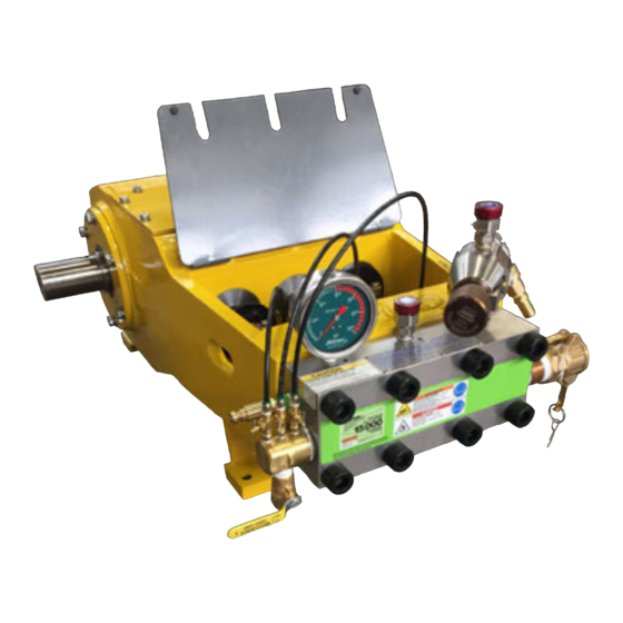
Need help?
Do you have a question about the 3000 series and is the answer not in the manual?
Questions and answers