Table of Contents
Advertisement
Quick Links
PRODUCT INSTRUCTIONS
6" J-FORCE™
JF6X15 (PN 64915)
JF6X22 (PN 65380 & 65381)
PI-178
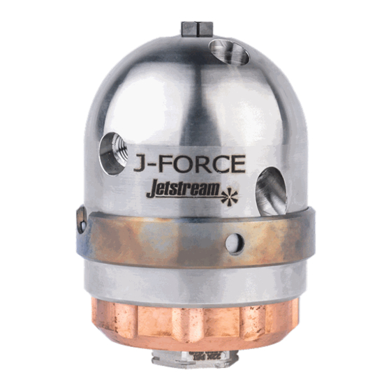
The 6" J-Force
TM
navigate and clean 6" pipes with up to 90° bends. The 6" J-Force has
front, side, and rear jets that clear blockages, clean, and provide thrust
to propel the tool down the pipe. The nozzle comes equipped with an
eddy-current braking system which controls rotation speed for maximum
cleaning power and minimum wear.
Read these instructions thoroughly before installing, connecting, or using the
J-FORCE nozzle. If any questions remain, call JETSTREAM at (800) 231-8192 or
(832) 590-1300. Also read the yellow JETSTREAM SAFETY WARNING pamphlet
included with the shipment of your new J-FORCE nozzle and reproduced inside
this publication. This product is sold with the understanding that the purchaser
agrees to thoroughly train all operators and maintenance personnel in the correct
and safe installation, operation and maintenance of the product and to provide
adequate supervision of personnel at all times. Retain these instructions for future
reference. If this product is resold or otherwise conveyed, purchaser must pass on
the instructions to the new user.
is a self-powered rotating nozzle designed to easily
Advertisement
Table of Contents

Related Manuals for JETStream J-FORCE JF6X15


Summary of Contents for JETStream J-FORCE JF6X15
- Page 1 Read these instructions thoroughly before installing, connecting, or using the J-FORCE nozzle. If any questions remain, call JETSTREAM at (800) 231-8192 or (832) 590-1300. Also read the yellow JETSTREAM SAFETY WARNING pamphlet included with the shipment of your new J-FORCE nozzle and reproduced inside this publication.
-
Page 2: Table Of Contents
Table of Contents Section 1: Safety ................3 Section 2: Product Description ............12 Section 3: Preparation for Use .............14 Section 4: Setup ................15 Section 5: Operation ..............16 Section 6: Service ................17 Section 7: Troubleshooting ............21 Appendix A Exploded Views .................22 Parts Placement ................23 Appendix B Accessories ................24 Bushing Removal Tool (PN 66967)..........24... -
Page 3: Section 1: Safety
Pressure Waterjetting Equipment” published by the Waterjet Technology Association, as well as any applicable OSHA regulations, standards and guidelines. Should any questions arise concerning safe and proper procedure, contact JETSTREAM prior to the installation or use at (800) 231-8192 or (832) 590-1300. July 2020 PI-178... - Page 4 GENERAL WATERBLAST 1. Use only clear, clean water in high pressure system. 2. Place barricades with warning signs or barricade tape around work area. 3. Outfit all operators with Personal Protective Equipment (PPE). Hard hat with plastic face shield, rainsuit, non-skid knee boots with metatarsal protection, gloves, ear protection and body armor rated for operating pressures are considered minimum safety equipment.
- Page 5 11. Properly tighten all high pressure connections. All NPT connections must have a minimum engagement of four (4) threads. Pipe (NPT) connections should be made up hand tight plus two (2) full wrenched turns. Do not tighten NPT threads past two (2) wrenched turns. Use wrench flats (when available) or a properly adjusted smooth jaw plier wrench (JS PN 64119) for tightening components.
- Page 6 18. If equipment malfunctions or a system malfunction is suspected, immediately stop cleaning activity and relieve the pressure in the system before attempting any repairs. Always follow the manufacturer’s repair instructions. 19. Only trained persons should be authorized to perform any mainte- nance or repair.
- Page 7 7. Do not use a pressure relief valve as a combination relief and throttling device. 8. Keep relief valve dry during freezing conditions. NOTE: Pressure relief devices are imperative for the protection of both operator and equipment from dangerous over-pressurization. HIGH PRESSURE HOSE 1.
- Page 8 Wrench connection 1 1/2 - 2 turns past hand tight. A minimal thread engagement of four (4) threads should exist on all Jetstream NPT pipe connections. Use wrench flats (when available) or a properly adjusted smooth jaw plier wrench (JS PN 64119) to tighten nozzle.
- Page 9 “double back” toward operator within large diameter pipe. C. Anti-withdrawal device prevents the lance from exiting the tube or pipe. Contact JETSTREAM for additional information regarding these products. 9. Use only nozzles designed for use with flex lances (i.e. nozzle drilled with sufficient rearward orifices so nozzle pulls lance through tube.)
- Page 10 this clearance should be greater. Insufficient side clearance may cause lance to blow back toward operator. 4. Be sure nozzle, lance and adapter thread sizes are compatible before installing nozzle and adapter on lance. Do not use a rigid lance that has damaged or missing threads.
- Page 11 Do not put any piece of repaired equipment into service if its performance is questionable. If repaired equipment performance is questionable, call manufacturer of repair parts for assistance. This section concludes all the same information included in the yellow JETSTREAM SAFETY WARNING pamphlet (PI-082). July 2020 PI-178...
-
Page 12: Section 2: Product Description
Section 2: Product Description The 6” J-Force is a self-powered rotating nozzle that uses up to six JS4F or P4TC nozzles. The 6” J-Force has many features, including: • Spins on a film of high pressure water and has no ball bearings to replace. - Page 13 Product Specifications Model Name JF6X15 JF6X22 Maximum Operating Pressure (psi) 15,000 22,000 Minimum Operating Pressure (psi) 2,500 Maximum Flow (gpm) Maximum Operating Pressure (bar) 1000 1500 Minimum Operating Pressure (bar) Maximum Flow (l/min) Inlet Connection 1/2" NPT 9/16” MP or M24 Tube or Pipe I.D.
-
Page 14: Section 3: Preparation For Use
Section 3: Preparation for Use 3.0 The 6” J-Force is mounted to a flexible rubber waterblast hose that allows it to navigate 6” pipes with bends up to 90°. 3.1 Before use, disassemble the 6” J-Force and inspect the mandrel and bushing for wear, damage, o-ring condition, etc. -
Page 15: Section 4: Setup
NOTE: Nozzle configurations must be carefully selected to ensure that they provide the necessary pull and torque. If a non-standard configura- tion is required, contact a Jetstream representative to verify that it is safe and that the tool will function properly. -
Page 16: Section 5: Operation
Section 5: Operation 5.0 OPERATING J-FORCE As per the WJTA-IMCA Recommended Practices, all operators shall follow the OSHA regulations for personal protective equipment. (OSHA guidelines for Personal Protective Equipment are available in document number 3151-12R 2004, which can be obtained from www.osha.gov.) All operators shall be issued suitable head protection, eye protection, hearing protection, body protection, hand and foot protection and respira- tory protection (if needed). -
Page 17: Section 6: Service
Section 6: Service JF6X15 (PN 64915) JF6X22 (PN 65380 & 65381) CUTOUT TOWARDS FRONT OF TOOL Figure A 6” J-Force Body Assembly Item Part Number Description 64827 ADJUSTER, BRAKE 64915 J-FORCE NOZZLE 66740 AY 1/2” NPT INLET NUT 65380 J-FORCE NOZZLE 66348 AY 9/16”... - Page 18 6.0 6” J-FORCE MAINTENANCEWhen not in use, the 6” J-Force should be cleaned to remove any debris, deposits, or contaminants that could impede rotation, and sprayed with water-dispersing lubricant (e.g. WD- 40) for storage until next use. The 6” J-Force utilizes water-bearing technology coupled with an eddy- current braking system to control the rotation speed.
- Page 19 6.2 ASSEMBLY 1. Ensure the new mandrel (6a), flange bushing (6b), and head assembly (5) are clean. 2. Install new o-rings (6e) and seal rings (6d) onto the flange bushing (6b). Apply a light coat of o-ring lube to o-rings to reduce friction and ease installation.
- Page 20 7. Insert the thrust bearing (6c) into the front bore of the head assem- bly (5) so that it sits flat against the flange of the flange bushing (6b). 8. Hold the inlet nut (2) hex stationary in a vice or with a 1-1/4” wrench and push the mandrel (6a) through the flange bushing (6b) into the inlet nut (2).
-
Page 21: Section 7: Troubleshooting
Section 7: Troubleshooting 7.0 6” J-FORCE TROUBLESHOOTING Problem Possible Cause Remedy Will not spin Nozzles worn, plugged, Replace nozzles or wrong size O-ring / backup ring Replace o-rings / backup failure rings Galling between mandrel Replace damaged com- and flange bushing ponents (rebuild kit) Debris Clean*... -
Page 22: Appendix A Exploded Views
Appendix A Exploded Views JF6X15 (PN 64915) JF6X22 (PN 65380 & 65381) CUTOUT TOWARDS FRONT OF TOOL Figure C 6” J-Force Body Assembly Item Part Number Description 64827 ADJUSTER, BRAKE 64915 J-FORCE NOZZLE 66740 AY 1/2” NPT INLET NUT 65380 J-FORCE NOZZLE 66348 AY 9/16”... -
Page 23: Parts Placement
Parts Placement Figure D July 2020 PI-178... -
Page 24: Appendix B Accessories
KIT PN TOOL PN INLET CONNECTION KIT TYPE 65479 64915 1/2” NPT STARTER 65480 64915 1/2” NPT PREMIUM 65481 65380 9/16” MP STARTER 65482 65380 9/16” MP PREMIUM 65483 65381 STARTER 65484 65381 PREMIUM Appendix B Accessories Bushing Removal Tool (PN 66967) •... -
Page 25: P4Tc Nozzles
P4TC Nozzles • Low profile design for unobstructed pipe cleaning • Tungsten carbide orifice inserts significantly outlast conventional nozzle orifice material • Tapered geometry provides highly cohesive, distortion-free waterjets for concentrated, work savings cleaning and cutting power • Straight (0°) pattern •... -
Page 26: Appendix C Flow Charts
Appendix C Flow Charts 6" J‐Force, Puller (Rear Jets) 2500 psi 5000 psi 7500 psi Flow Nozzle Diameter (inches) Nozzle Diameter (inches) Nozzle Diameter (inches) Pull Pull Pull (gpm) (lbf) (lbf) (lbf) Front,Fwd x 2,Side x 2 Rear x 2 Front,Fwd x 2,Side x 2 Rear x 2 Front,Fwd x 2,Side x 2 Rear x 2 ‐84 Plug 0.075 ‐81 Plug 0.090 ‐87 Plug 0.093 ‐101 Plug 0.082 ‐97 Plug 0.098 ‐122 Plug 0.090... - Page 27 6" J‐Force, Polisher (Forward Nozzles Plugged) 2500 psi 5000 psi 7500 psi Flow Pull Pull Pull (gpm) (lbf) (lbf) (lbf) Side x 2 Rear x 2 Side x 2 Rear x 2 Side x 2 Rear x 2 ‐45 0.057 0.047 ‐41 0.063 0.042 ‐59 0.052 0.057 ‐48 0.063 0.047 ‐35 0.073 0.032 ‐41 0.075 0.052 ‐70 0.052 0.063 ‐46 0.073 0.057 ‐41...
- Page 28 ‐56 0.067 0.067 ‐57 0.067 0.052 ‐53 0.073 0.063 ‐58 0.069 0.052 ‐54 0.075 0.063 ‐66 0.067 0.057 ‐58 0.073 0.067 ‐75 0.063 0.063 ‐61 0.073 0.069 ‐61 0.073 0.052 ‐62 0.075 0.069 ‐62 0.075 0.052 ‐67 0.073 0.073 ‐76 0.067 0.063 ‐67...
- Page 29 6" J‐Force, Unplugger (Side Nozzles Plugged) 2500 psi 5000 psi 7500 psi Flow Pull Pull Pull (gpm) (lbf) Fwd x 2 Rear x 2 (lbf) Fwd x 2 Rear x 2 (lbf) Fwd x 2 Rear x 2 ‐95 0.018 0.082 ‐91 0.022 0.082 ‐87 0.026 0.082 ‐84 0.029 0.082 ‐92 0.018 0.098 ‐38 0.047 0.075 ‐90 0.022 0.098 ‐71 0.038 0.082 ‐62...
- Page 30 2500 psi 5000 psi 7500 psi Flow Pull Pull Pull (gpm) (lbf) (lbf) (lbf) Fwd x 2 Rear x 2 Fwd x 2 Rear x 2 Fwd x 2 Rear x 2 ‐95 0.018 0.082 ‐91 0.022 0.082 ‐87 0.026 0.082 ‐84 0.029 0.082 ‐92 0.018 0.098 ‐38 0.047 0.075 ‐90 0.022 0.098 ‐71 0.038 0.082 ‐62 0.042...
- Page 31 6" J‐Force, Universal 2500 psi 5000 psi 7500 psi Flow Nozzle Diameter (inches) Nozzle Diameter (inches) Pull Nozzle Diameter (inches) Pull Pull (gpm) (lbf) (lbf) (lbf) Fwd x 2, Side x 2 Rear x 2 Fwd x 2, Side x 2 Rear x 2 Fwd x 2, Side x 2 Rear x 2 ‐62 0.024 0.069 ‐53 0.029 0.067 ‐39 0.035 0.063 ‐76 0.022 0.075 ‐54 0.032 0.069 ‐78 0.018 0.090 ‐66 0.029 0.073 ‐76...
- Page 32 ‐70 0.032 0.090 ‐64 0.035 0.075 ‐77 0.029 0.093 ‐41 0.042 0.069 ‐91 0.022 0.098 ‐60 0.038 0.075 ‐89 0.026 0.098 ‐117 0.018 0.090 ‐42 0.047 0.082 ‐115 0.020 0.090 ‐76 0.020 0.125 ‐87 0.029 0.098 ‐54 0.042 0.075 ‐75 0.026 0.125 ‐85...
- Page 33 This page intentionally left blank. July 2020 PI-178...
-
Page 34: Warranty
Exclusive Remedy. Should any warranted product fail during the warranty period, Jetstream will cause to be repaired or replaced, as Jetstream may elect, any part or parts of such Waterblast Unit, Bareshaft Pump, or Fluid End that the examination discloses in Jetstream’s sole judgment to be defective in material or factory workmanship. - Page 35 6. Items subject to misuse, negligence, accident or improper mainte- nance. *NOTE* The use of any part other than ones approved by Jetstream may invalidate this warranty. Jetstream reserves the right to determine, in its sole discretion, if the use of non-approved parts invalidates the warranty.
- Page 36 Capacity ratings, features, and specifications vary depending upon the model and type of service. Application approvals must be obtained from Jetstream; contact your representative for application approval. We reserve the right to change or modify our product specifications, configurations, or dimensions at any time without notice.
Need help?
Do you have a question about the J-FORCE JF6X15 and is the answer not in the manual?
Questions and answers