Meggitt vibro-meter VM600 Hardware Manual
Machinery protection system (mps) – standard version
Hide thumbs
Also See for vibro-meter VM600:
- Hardware manual (362 pages) ,
- Manual (212 pages) ,
- Quick start manual (88 pages)
Table of Contents
Advertisement
HARDWARE MANUAL
Title page
VM600
machinery protection system (MPS)
– standard version
Document reference MAMPS-HW/E
Edition 18 – March 2022
Meggitt SA, Route de Moncor 4, Case postale, 1701 Fribourg, Switzerland
Tel: +41 26 407 1111
Fax: +41 26 407 1660
energy@ch.meggitt.com
www.meggittsensing.com/energy
www.meggitt.com
Advertisement
Table of Contents

Subscribe to Our Youtube Channel
Related Manuals for Meggitt vibro-meter VM600


Summary of Contents for Meggitt vibro-meter VM600
- Page 1 VM600 machinery protection system (MPS) – standard version Document reference MAMPS-HW/E Edition 18 – March 2022 Meggitt SA, Route de Moncor 4, Case postale, 1701 Fribourg, Switzerland Tel: +41 26 407 1111 Fax: +41 26 407 1660 energy@ch.meggitt.com www.meggittsensing.com/energy www.meggitt.com...
-
Page 2: Revision Record Sheet
08.05.2012 Peter Ward in the front and cards in the rear of a rack. Updated in accordance with the latest Meggitt brand guidelines. Added information on the IRC4 intelligent relay card. Reorganised slot number coding information for racks and 19.12.2012 Peter Ward cards. - Page 3 Date Written by / Edition Description Signature of issue modified by Added information on VM600 MPS rack (CPUM) security (see 1.3 Communicating with the VM600 MPS 6 CPUM / IOCN card pair). Clarified the maximum current available for a VM600 rack using two RPS6U rack power supplies (see 2.10.6 Racks with two RPS6U rack power supplies in order to supply...
- Page 4 Date Written by / Edition Description Signature of issue modified by Added additional information, including current input and voltage input transfer ratios, to 4.4.3 Analog outputs. Added additional important safety information in Electrical safety and installation on page xvi, Hazardous voltages and the risk of electric shock on page xvii, Hot surfaces and the...
- Page 5 Date Written by / Edition Description Signature of issue modified by Added a statement that Meggitt SA product certifications and warranties are valid only for products purchased directly from Meggitt SA or an authorised distributor (see IMPORTANT NOTICES). Updated Figure 4-6 Figure 5-3 to use “Alarm Reset”,...
- Page 6 Date Written by / Edition Description Signature of issue modified by Clarified that a fully populated VM600 system rack (ABE04x) should be considered as a heavy object that requires two people to safely handle manually (see Heavy objects and the risk of injury on page xvii 8.3.4 Instructions for locating and mounting).
- Page 7 Document released by Technical Publications Peter Ward 31.03.2022 The duly signed master copy of this page is stored by the Technical publications department of Meggitt SA and can be obtained by writing to Technical publications. Document reference MAMPS-HW/E HARDWARE MANUAL...
-
Page 8: Important Notices
Unless otherwise expressly agreed in writing with Meggitt SA, you assume all risks and liability associated with use of the product. Meggitt SA takes no responsibility for any statements related to the product which are not contained in a current English language Meggitt SA publication, nor for any statements contained in extracts, summaries, translations or any other documents not authored and produced by Meggitt SA. -
Page 9: Preface
It offers information concerning the installation, configuration and general use of the system. ® About Meggitt and vibro-meter Meggitt PLC is a global engineering group, headquartered in the UK, specialising in the design and manufacture of high-performance components and systems for aerospace and energy markets. - Page 10 Structure of the manual This section gives an overview of the structure of the document and the information contained within it. Some information has been deliberately repeated in different sections of the document to minimise cross-referencing and to facilitate understanding through reiteration. The chapters are presented in a logical order.
- Page 11 Part II: Installing VM600 MPS hardware and using the system Chapter 8 Installation – Provides information on installing the cards and power supplies in the VM600 MPS rack. Chapter 9 Configuration of MPC4 / IOC4T cards – Describes the connectors on the IOC4T card. Includes typical connection diagrams for measurement signal sensors (for example, accelerometers, proximity probes) and speed signal sensors.
- Page 12 VibroSmart distributed monitoring system (DMS) modules such as the VSI010 and VSV300. ® VM600 IRC4 Configurator is proprietary software from the Meggitt vibro-meter product line that can configure and manage IRC4 cards. Related publications and documentation For further information on the use of a VM600 machinery protection system (MPS), refer to ®...
- Page 13 For information on the use of a VM600 condition monitoring system (CMS), refer to the ® following Meggitt vibro-meter documentation: • VM600 condition monitoring system (CMS) hardware manual (document reference MACMS-HW/E). NOTE: Ensure that the latest version of related documentation is being used by obtaining ®...
- Page 14 THIS PAGE INTENTIONALLY LEFT BLANK HARDWARE MANUAL Document reference MAMPS-HW/E VM600 machinery protection system (MPS) Edition 18 - March 2022...
-
Page 15: Safety
SAFETY Symbols and styles used in this manual The following symbols are used in this manual where appropriate: The WARNING safety symbol HIS INTRODUCES DIRECTIVES PROCEDURES OR PRECAUTIONARY MEASURES WHICH MUST BE EXECUTED OR FOLLOWED AILURE TO OBEY A WARNING MIGHT RESULT IN INJURY TO THE OPERATOR AND OR THIRD PARTIES OR RESULT IN DAMAGE TO... - Page 16 All personnel who are liable to operate the equipment described in this manual should be trained in the correct safety procedures. Meggitt does not accept any liability for injury or material damage caused by failure to obey any safety-related instructions or due to any modification, transformation or repair carried out on the equipment without written permission from Meggitt SA.
- Page 17 Hazardous voltages and the risk of electric shock VM600 AZARDOUS VOLTAGES EXIST WITHIN A RACK VM600 HEN A CARD PANEL OR POWER SUPPLY IS REMOVED FROM A RACK – – RACK BACKPLANE CONTAINING HAZARDOUS VOLTAGES IS EXPOSED AND THERE IS THE RISK OF ELECTRIC SHOCK AS INDICATED BY THE USE OF THE FOLLOWING WARNING LABEL ON THE EQUIPMENT (PCB)
- Page 18 Do not connect with incompatible products or accessories. Only use replacement parts and accessories intended for use with VM600 racks that have been approved by Meggitt SA. Using incompatible replacement parts and accessories could be dangerous and may damage the equipment or result in injury.
-
Page 19: Table Of Contents
TABLE OF CONTENTS TITLE PAGE ............. . . i REVISION RECORD SHEET . - Page 20 2.10.7 VM600 racks and power supply redundancy ..... . 2-24 2.10.8 Front panels ..........2-27 2.10.9 Associated rear panels .
- Page 21 4.4.3 Analog outputs ..........4-12 4.4.4 DC outputs .
- Page 22 5.8.3 Danger Bypass function ........5-9 5.8.4 Channel inhibit function.
- Page 23 7.14 Differential quasi-static pressure monitoring......7-28 7.15 Quasi-static temperature monitoring........7-28 7.16 Differential quasi-static temperature monitoring .
- Page 24 Configuring the four local relays on the IOC4T ......9-30 9.4.1 Relay terminology ......... . . 9-31 9.4.2 Operation of relays .
- Page 25 11 USING THE RLC16 CARD ..........11-1 11.1 Definition of screw terminals on the RLC16 card .
- Page 26 13.6 Connectors on the IOCN card ........13-15 13.6.1 Modular connector pinouts .
- Page 27 Part IV: Appendices A ENVIRONMENTAL SPECIFICATIONS ........A-1 Overall.
- Page 28 THIS PAGE INTENTIONALLY LEFT BLANK HARDWARE MANUAL Document reference MAMPS-HW/E VM600 machinery protection system (MPS) Edition 18 - March 2022 xxviii...
-
Page 29: Introduction
1.2 General overview The VM600 series of machinery protection and condition monitoring systems from Meggitt’s ® vibro-meter product line are based around a 19" rack (1U or 6U) containing various types of cards, depending on the application. - Page 30 INTRODUCTION General overview In general, a VM600 rack used for machinery protection can contain: • Only MPC4 / IOC4T card pairs • Only AMC8 / IOC8T card pairs • A combination of MPC4 / IOC4T and AMC8 / IOC8T card pairs. Depending on the application, the following type of cards can also be installed in the rack: RLC16 relay card (16 relays) and IRC4 intelligent relay card (eight relays combined as either 4 DPDT or 8 SPDT).
- Page 31 INTRODUCTION General overview IOCN input/output card IOC4T input/output cards IRC4 intelligent relay card RLC16 ASPS relay card ABE040 19” x 6U rack CPUM MPC4 modular CPU machinery card protection RPS6U card rack power supplies Figure 1-1: Front-view drawing of an example VM600 machinery protection system (MPS) featuring MPC4 / IOC4T card pairs Document reference MAMPS-HW/E HARDWARE MANUAL...
- Page 32 INTRODUCTION General overview MPC4 machinery CPUM protection card RPS6U modular CPU card rack power supply ABE040 19” x 6U rack IOCN input/output card IOC4T input/output card Relay outputs ASPS Rear panel IRC4 RLC16 for rack intelligent relay card power supply relay card Figure 1-2: Rear-view drawing of an example VM600 machinery protection system (MPS) featuring MPC4 / IOC4T card pairs...
-
Page 33: Communicating With The Vm600 Mps
INTRODUCTION Communicating with the VM600 MPS 1.3 Communicating with the VM600 MPS A VM600 MPS can be configured in several ways, depending on the hardware installed in the system rack (ABE04x). Figure 1-3 shows the various possibilities for communicating with the system. - Page 34 INTRODUCTION Communicating with the VM600 MPS NOTE: A VM600 MPS in a 19″ system rack (ABE04x) containing a CPUM card can implement specific rack security features in order to limit the functionality of the MPS that are available via the CPUM to Ethernet-based connections, such as the VM600 MPSx software, the CPUM Configurator software or a Modbus TCP connection.
- Page 35 INTRODUCTION Communicating with the VM600 MPS Signal connections Rear of VM600 (ABE04x) rack Backplane Front of VM600 (ABE04x) rack Computer Ethernet RS-232 Modbus Figure 1-3: Methods of communicating with a VM600 MPS system Document reference MAMPS-HW/E HARDWARE MANUAL Edition 18 - March 2022 VM600 machinery protection system (MPS) 1 - 7...
- Page 36 INTRODUCTION Communicating with the VM600 MPS THIS PAGE INTENTIONALLY LEFT BLANK HARDWARE MANUAL Document reference MAMPS-HW/E VM600 machinery protection system (MPS) Edition 18 - March 2022 1 - 8...
-
Page 37: Overview Of Vm600 Mps Hardware
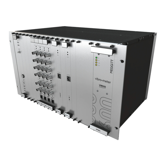
OVERVIEW OF VM600 MPS HARDWARE Racks 2 OVERVIEW OF VM600 MPS HARDWARE This chapter provides a brief overview of the physical appearance of VM600 MPS hardware. Functional information is also given for certain elements (push buttons, LEDs and so on) on the panels. - Page 38 OVERVIEW OF VM600 MPS HARDWARE Racks Front view (PS2) (PS1) Rear view Side view Front Figure 2-1: Views of a typical VM600 rack (ABE040) with several cards installed (machinery protection cards only) HARDWARE MANUAL Document reference MAMPS-HW/E VM600 machinery protection system (MPS) Edition 18 - March 2022 2 - 2...
- Page 39 OVERVIEW OF VM600 MPS HARDWARE Racks 2.1.1.1 Slot number coding for cards in the rear of a VM600 system rack Most cards installed in the rear of a VM600 system rack (ABE04x) use an electronic keying mechanism to help ensure that the card is installed in the correct slot (for example, in the slot directly behind the associated processing card in the front of the rack).
- Page 40 OVERVIEW OF VM600 MPS HARDWARE Racks Card in the front of the rack Card in the rear of the rack (for example, MPC4 or AMC8) (for example, IOC4T, IOC8T or IRC4) Micro-switches (Example: 1011 for slot 11) Slot number Address (address) decoder assignation...
-
Page 41: Vm600 Slimline Rack - 19" Rack With A Height Of 1U (Abe056)
OVERVIEW OF VM600 MPS HARDWARE Racks 2.1.2 VM600 slimline rack – 19" rack with a height of 1U (ABE056) A VM600 MPS can be housed in a slimline 19 inch rack (84TE) with a height of 1U (1HE), known as the VM600 slimline rack (ABE056). It is a 19″ × 1U rack with 1 × VME slot in the front of the rack and 2 ×... - Page 42 OVERVIEW OF VM600 MPS HARDWARE Racks Front view Rear view (AC-input version) POWER SUPPLY POWER SUPPLY 90-264 VAC CHECK 100 Wmax Rear view (DC-input version) POWER SUPPLY POWER SUPPLY 18-58VDC CHECK 60Wmax Top view 3D view Figure 2-4: Views of a typical ABE056 rack NOTE: The wiring of the DC power supply input connector, as shown in “Rear view (DC version)”...
- Page 43 OVERVIEW OF VM600 MPS HARDWARE Racks 2.1.2.1 Slot number coding for cards in the rear of a VM600 slimline rack Most cards installed in the rear of a VM600 slimline rack (ABE056) use an electronic keying mechanism to help ensure that the card is installed in the correct slot (for example, in the slot directly behind the associated processing card in the front of the rack).
- Page 44 OVERVIEW OF VM600 MPS HARDWARE Racks 2.1.2.2 Changing the slot number for a VM600 slimline rack To configure slot number coding for a VM600 slimline rack (ABE056), a DIP switch on the rack’s backplane must be set in order to match the slot number used for the input/output card by the configuration software (for example, VM600 MPSx for a MPC4 / IOC4T card pair).
- Page 45 OVERVIEW OF VM600 MPS HARDWARE Racks this type of rack. See 2.1.2.1 Slot number coding for cards in the rear of a VM600 slimline rack. For the rack DIP switch, this translates to: • Two LSBs = 1 and all other bits/switches = 0. (Slot 03 = 0011 in binary =>...
-
Page 46: Mpc4 Machinery Protection Card (Abe04X And Abe056)
OVERVIEW OF VM600 MPS HARDWARE MPC4 machinery protection card (ABE04x and ABE056) 2.2 MPC4 machinery protection card (ABE04x and ABE056) The MPC4 card has the following panel elements (see Figure 2-8): One global DIAG/STATUS indicator for the MPC4 IOC4T card pair This multi-coloured, multi-function LED is used to indicate: •... - Page 47 OVERVIEW OF VM600 MPS HARDWARE MPC4 machinery protection card (ABE04x and ABE056) DIAG/STATUS indicator for the MPC4 / IOC4T card pair. The colours of the LED have the following significance: * Green (continuous) – Normal operation (configuration valid with no active alarms and no errors).
-
Page 48: Ioc4T Input/Output Card (Abe04X And Abe056)
OVERVIEW OF VM600 MPS HARDWARE IOC4T input/output card (ABE04x and ABE056) 2.3 IOC4T input/output card (ABE04x and ABE056) The IOC4T panel (rear of rack) contains three terminal strips, identified as J1, J2 and J3 (see Figure 2-9). Each strip consists of a socket and a mating connector, which contains 16 screw terminals. -
Page 49: Amc8 Analog Monitoring Card (Abe04X And Abe056)
OVERVIEW OF VM600 MPS HARDWARE AMC8 analog monitoring card (ABE04x and ABE056) 2.4 AMC8 analog monitoring card (ABE04x and ABE056) The AMC8 card has the following panel elements (see Figure 2-10): One global DIAG/STATUS indicator for the AMC8 IOC8T card pair This multi-coloured, multi-function LED is used to indicate: •... - Page 50 OVERVIEW OF VM600 MPS HARDWARE IOC8T input/output card (ABE04x and ABE056) DIAG/STATUS indicator for the AMC8 / IOC8T card pair. The colours of the LED have the following significance: VM600 * Green (continuous) – Normal operation (configuration valid with no active alarms and no errors).
-
Page 51: Cpum Modular Cpu Card (Abe04X Only)
OVERVIEW OF VM600 MPS HARDWARE CPUM modular CPU card (ABE04x only) Connector J1 (mating connector with 24 cage clamp terminals) Connector J2 (mating connector with 24 cage clamp terminals) Connector J3 (mating connector with 20 cage clamp terminals) Connector J4 (mating connector with 12 screw terminals) SLOT ERROR indicator... - Page 52 OVERVIEW OF VM600 MPS HARDWARE IOCN input/output card (ABE04x only) Output signal Slot (module number) (for example, Channel 1, Output 1) Danger threshold Enlarged view of display Alert threshold Bargraph (51 segments) Digital display Measurement unit Green diagnostic LED: Rectifier * Off –...
- Page 53 OVERVIEW OF VM600 MPS HARDWARE IOCN input/output card (ABE04x only) ‘RS’ connector (6P6C (RJ12/RJ25)) for secondary serial connection, used for Modbus RTU communications. Supports RS-232 or RS-485 (2-wire or 4-wire) communications (selectable by jumpers on the CPUM card). ‘A’ serial connectors (6P6C (RJ12/RJ25)) used for Modbus RTU communications –...
-
Page 54: Rlc16 Relay Card (Abe04X And Abe056)
OVERVIEW OF VM600 MPS HARDWARE RLC16 relay card (ABE04x and ABE056) 2.8 RLC16 relay card (ABE04x and ABE056) The RLC16 panel (rear of rack) contains three terminal strips, identified as J1, J2 and J3 (see Figure 2-14). Each strip consists of a socket and a mating connector, which contains 16 screw terminals. -
Page 55: Irc4 Intelligent Relay Card (Abe04X And Abe056)
OVERVIEW OF VM600 MPS HARDWARE IRC4 intelligent relay card (ABE04x and ABE056) 2.9 IRC4 intelligent relay card (ABE04x and ABE056) The IRC4 panel (rear of rack) contains two terminal strips, identified as J1 and J2 (see Figure 2-15). Each strip consists of a socket and a mating connector, which contains 16 screw terminals. -
Page 56: Rps6U Rack Power Supply (Abe04X Only)
OVERVIEW OF VM600 MPS HARDWARE RPS6U rack power supply (ABE04x only) 2.10RPS6U rack power supply (ABE04x only) 2.10.1 Different versions of the RPS6U rack power supply In 2016, the RPS6U rack power supply was improved to provide a higher output power of 330 W with higher-performance and higher-efficiency, which required a redesign of the underlying power supply circuitry. -
Page 57: Identifying Different Versions Of The Rps6U Rack Power Supply
– because the rack backplane may not support the additional currents involved. If you are considering this, please contact your Meggitt representative, who will help you to assess how many cards can be safely added to your system without replacing the rack. -
Page 58: Rps6U Rack Power Supply And Vm600 Card Considerations
To verify that a VM600 rack containing two RPS6U rack power supplies is a non-redundant or a redundant rack power supply configuration, contact your local Meggitt representative. 2.10.4 RPS6U rack power supply and VM600 card considerations The maximum number of cards that can be installed in a VM600 system rack (ABE04x) depends on RPS6U rack power supply considerations: •... -
Page 59: Racks With Two Rps6U Rack Power Supplies In Order To Support Rack Power Supply Redundancy
RLC16 relay cards, the power consumption of the rack should be calculated in order to determine the number of RPS6U power supplies required and the permitted modes of operation. Contact your local Meggitt representative for further information. 2.10.5 Racks with two RPS6U rack power supplies in order to support rack power... -
Page 60: Vm600 Racks And Power Supply Redundancy
VM600 rack with two 300 W RPS6U power supplies installed and operating non-redundantly is typically necessary for applications using more than nine cards. Contact your local Meggitt representative for further information. 2.10.7 VM600 racks and power supply redundancy... - Page 61 OVERVIEW OF VM600 MPS HARDWARE RPS6U rack power supply (ABE04x only) NOTE: A VM600 rack can implement internal rack power supply redundancy only, external power supply redundancy only, or both internal rack power supply redundancy and external power supply redundancy at the same time – depending on the number and version of RPS6U power supplies (internally), the number and type of mains power supplies (externally) and the associated rear panel that connects the power supplies together.
- Page 62 OVERVIEW OF VM600 MPS HARDWARE RPS6U rack power supply (ABE04x only) Table 2-1: VM600 racks, power supply redundancy and associated rear panels (continued) Power supply Mains inputs redundancy Associated rear panel Number Commoned External Internal and type 2.10.9.12 AC-input (230 VAC only) panel with commoned individual inputs 2 AC (200-582-960-NHh)
-
Page 63: Front Panels
OVERVIEW OF VM600 MPS HARDWARE RPS6U rack power supply (ABE04x only) 2.10.8 Front panels Figure 2-16 shows the panels of RPS6U rack power supplies with different inputs: AC or DC. IN, AC or DC LED: Green indicates that the external mains supply is present and is within the normal range. -
Page 64: Associated Rear Panels
OVERVIEW OF VM600 MPS HARDWARE RPS6U rack power supply (ABE04x only) 2.10.9 Associated rear panels VM600 OR SAFETY REASONS RACK SLOT CARD POSITION NOT POPULATED VM600 BY A CARD MUST BE COVERED BY A BLANK PANEL 2.10.9.1 DC-input panel with a common input NOTE: For a VM600 system rack (ABE04x) operating with an external DC-mains supply, the DC-input panel with a common input is the standard associated rear panel. - Page 65 OVERVIEW OF VM600 MPS HARDWARE RPS6U rack power supply (ABE04x only) vibro meter DATA MATRIX DC input label (Rear panel (Internal to connections) VM600 rack) (a) Rear panel (b) Wiring details Figure 2-17: DC-input panel with a common input Document reference MAMPS-HW/E HARDWARE MANUAL Edition 18 - March 2022 VM600 machinery protection system (MPS)
- Page 66 OVERVIEW OF VM600 MPS HARDWARE RPS6U rack power supply (ABE04x only) 2.10.9.2 DC-input panel with a common input (special earth terminal) This rear panel has one DC input with a screw-terminal connector that provides a common input to DC-input versions of the RPS6U power supplies in a VM600 rack. It also provides a special earth terminal (identified as M.A.L.T.).
- Page 67 OVERVIEW OF VM600 MPS HARDWARE RPS6U rack power supply (ABE04x only) 2.10.9.3 DC-input panel with individual inputs This rear panel has two DC inputs with screw-terminal connectors that provide individual inputs to DC-input versions of the RPS6U power supplies in a VM600 rack. Figure 2-19 shows: a.
- Page 68 OVERVIEW OF VM600 MPS HARDWARE RPS6U rack power supply (ABE04x only) 2.10.9.4 DC-input panel with commoned individual inputs This rear panel has two DC inputs with screw-terminal connectors that provide a common input to DC-input versions of the RPS6U power supplies in a VM600 rack. Figure 2-20 shows: a.
- Page 69 OVERVIEW OF VM600 MPS HARDWARE RPS6U rack power supply (ABE04x only) 2.10.9.5 AC-input (120/230 V ) panel with a common input (mains socket and on/off switch) NOTE: For a VM600 system rack (ABE04x) operating with an external AC-mains supply, the AC-input panel with a common input is the standard associated rear panel. This rear panel has one AC input (120/230 V ) with mains socket and on/off switch that provides a common input to the AC-input version of the RPS6U power supplies in a VM600...
- Page 70 OVERVIEW OF VM600 MPS HARDWARE RPS6U rack power supply (ABE04x only) 2.10.9.6 AC-input (120/230 V ) panel with a common input (screw-terminal connector and on/off switch) This rear panel has one AC input (120/230 V ) with screw-terminal connector, on/off switch and rear-panel fuses that provides a common input to the AC-input version of the RPS6U power supplies in a VM600 rack.
- Page 71 OVERVIEW OF VM600 MPS HARDWARE RPS6U rack power supply (ABE04x only) 2.10.9.7 AC-input (120/230 V ) panel with a common input (screw-terminal connector) This rear panel has one AC input (120/230 V ) with screw-terminal connector and rear-panel fuses that provides a common input to the AC-input version of the RPS6U power supplies in a VM600 rack.
- Page 72 OVERVIEW OF VM600 MPS HARDWARE RPS6U rack power supply (ABE04x only) 2.10.9.8 AC-input (120/230 V ) panel with individual inputs (mains sockets and on/off switches) This rear panel has two AC inputs (120/230 V ) with mains sockets and on/off switches that provide individual inputs to the AC-input version of the RPS6U power supplies in a VM600 rack.
- Page 73 OVERVIEW OF VM600 MPS HARDWARE RPS6U rack power supply (ABE04x only) vibro meter DATA MATRIX (a) Rear panel (Rear panel (Internal to connections) VM600 rack) (b) Wiring details Figure 2-24: AC-input (120/230 V ) panel with individual inputs (mains sockets and on/off switches) Document reference MAMPS-HW/E HARDWARE MANUAL Edition 18 - March 2022...
- Page 74 OVERVIEW OF VM600 MPS HARDWARE RPS6U rack power supply (ABE04x only) 2.10.9.9 AC-input (120/230 V ) panel with individual inputs (screw-terminal connectors and on/off switches) This rear panel has two AC inputs (120/230 V ) with screw-terminal connectors, on/off switches and rear-panel fuses that provide individual inputs to the AC-input version of the RPS6U power supplies in a VM600 rack.
- Page 75 OVERVIEW OF VM600 MPS HARDWARE RPS6U rack power supply (ABE04x only) 2.10.9.10 AC-input (120/230 V ) panel with individual inputs (screw-terminal connectors) This rear panel has two AC inputs (120/230 V ) with screw-terminal connectors and rear-panel fuses that provide individual inputs to the AC-input version of the RPS6U power supplies in a VM600 rack.
- Page 76 OVERVIEW OF VM600 MPS HARDWARE RPS6U rack power supply (ABE04x only) 2.10.9.11 AC-input (120 V only) panel with commoned individual inputs This rear panel has two AC inputs (120 V only) with mains sockets and on/off switches that provide a common input to the AC-input version of the RPS6U power supplies in a VM600 rack.
- Page 77 OVERVIEW OF VM600 MPS HARDWARE RPS6U rack power supply (ABE04x only) vibro meter DATA MATRIX (a) Rear panel (Rear panel (Internal to connections) VM600 rack) (b) Wiring details Figure 2-27: AC-input (120 V only) panel with commoned individual inputs Document reference MAMPS-HW/E HARDWARE MANUAL Edition 18 - March 2022 VM600 machinery protection system (MPS)
- Page 78 OVERVIEW OF VM600 MPS HARDWARE RPS6U rack power supply (ABE04x only) 2.10.9.12 AC-input (230 V only) panel with commoned individual inputs This rear panel has two AC inputs (230 V only) with mains sockets and on/off switches that provide a common input to the AC-input version of the RPS6U power supplies in a VM600 rack.
- Page 79 OVERVIEW OF VM600 MPS HARDWARE RPS6U rack power supply (ABE04x only) vibro meter DATA MATRIX (a) Rear panel (Rear panel (Internal to connections) VM600 rack) (b) Wiring details Figure 2-28: AC-input (230 V only) panel with commoned individual inputs Document reference MAMPS-HW/E HARDWARE MANUAL Edition 18 - March 2022 VM600 machinery protection system (MPS)
- Page 80 OVERVIEW OF VM600 MPS HARDWARE RPS6U rack power supply (ABE04x only) 2.10.9.13 Combined AC-input (120/230 V ) and DC-input panel with individual inputs This rear panel has one AC input (120/230 V ) with mains socket and on/off switch and one DC input with screw-terminal connector that provide individual inputs to the AC-input version and DC-input versions of the RPS6U power supplies in a VM600 rack.
- Page 81 OVERVIEW OF VM600 MPS HARDWARE RPS6U rack power supply (ABE04x only) vibro meter DATA MATRIX (a) Rear panel (Rear panel (Internal to connections) VM600 rack) (b) Wiring details Figure 2-29: Combined AC-input (120/230 V ) and DC-input panel with individual inputs Document reference MAMPS-HW/E HARDWARE MANUAL Edition 18 - March 2022...
-
Page 82: Power Supply Check Relay
OVERVIEW OF VM600 MPS HARDWARE RPS6U rack power supply (ABE04x only) 2.10.10 Power supply check relay The power supply check relay provides an indication that the +5 V, +12 V and −12 V supplies are being correctly generated and delivered by the RPS6U rack power supply or supplies to the VM600 system rack (ABE04x) backplane. - Page 83 OVERVIEW OF VM600 MPS HARDWARE RPS6U rack power supply (ABE04x only) +5 V PWS1 On rear panel +5 V PWS2 Normally closed (NC) Normally open (NO) Common (COM) PS2 (RPS6U) PS1 (RPS6U) +5 V +5 V PWS2 PWS1 –12 V –12 V PWS2 PWS1...
-
Page 84: Power Supply Labelling
OVERVIEW OF VM600 MPS HARDWARE RPS6U rack power supply (ABE04x only) When only the second RPS6U (PS2) is installed (slots 15 to 17): • Jumper J16 must be closed • Jumper J17 must be left open. When both RPS6Us (PS1 and PS2) are installed: •... - Page 85 OVERVIEW OF VM600 MPS HARDWARE RPS6U rack power supply (ABE04x only) Rated DC supply voltage range: (Corresponding rack power supply PNR / model) 18-32VDC (200-582-200-xxx / SIM-275D-24) 38.4-57.6VDC (200-582-200-xxx / SIM-275D-48) 57.6-100VDC (200-582-200-xxx / SIM-275D-72) 80-145VDC (200-582-200-xxx / SIM-275D-B0) Rated AC supply voltage range and its frequency: (Corresponding rack power supply PNR / model) 115-230VAC 50/60Hz (200-582-500-xxx / SIM-275A) Maximum active power...
- Page 86 OVERVIEW OF VM600 MPS HARDWARE RPS6U rack power supply (ABE04x only) 2.10.12 Auxiliary sensor power supply The following versions of the auxiliary sensor power supply (ASPS) are available for operation with an RPS6U: • An ASPS intended for use with an AC-mains supply. NOTE: As it requires an AC-mains supply input, the ASPS can only be used when an AC-input version of the RPS6U is also mounted in the rack.
- Page 87 OVERVIEW OF VM600 MPS HARDWARE RPS1U rack power supply (ABE056 only) 2.11RPS1U rack power supply (ABE056 only) The following versions of the RPS1U rack power supply are available: • An RPS1U for use with an AC-mains supply. • An RPS1U for use with a DC-mains supply. The different versions are distinguished by their ordering number (refer to the VM600 slimline rack (ABE056) data sheet).
- Page 88 OVERVIEW OF VM600 MPS HARDWARE RPS1U rack power supply (ABE056 only) On rear panel +5 V +5 V Normally closed (NC) Normally open (NO) Common (COM) –12 V +12 V Figure 2-34: Operation of the power supply check relay for the RPS1U power supply installed in a VM600 rack (ABE056) HARDWARE MANUAL Document reference MAMPS-HW/E...
- Page 89 OVERVIEW OF VM600 MPS HARDWARE RPS1U rack power supply (ABE056 only) 2.11.2 Power supply labelling Information regarding the DC and AC inputs for the RPS1U power supply used by the VM600 slimline rack (ABE056) is available on labels on the top and rear of the rack (see Figure 2-35).
- Page 90 OVERVIEW OF VM600 MPS HARDWARE RPS1U rack power supply (ABE056 only) THIS PAGE INTENTIONALLY LEFT BLANK HARDWARE MANUAL Document reference MAMPS-HW/E VM600 machinery protection system (MPS) Edition 18 - March 2022 2 - 54...
-
Page 91: General System Description
GENERAL SYSTEM DESCRIPTION System elements 3 GENERAL SYSTEM DESCRIPTION 3.1 System elements In order to gain an understanding of the operation of a VM600 machinery protection system (MPS), it is necessary to consider the interaction of the principal elements making up this system, namely: ABE04x (19"... - Page 92 This card handles the management of signals, alarm levels, signal processing and so on. The user is able to modify parameters concerning these operations by using one of the VM600 MPSx software packages (MPS1 or MPS2), from the Meggitt ®...
- Page 93 GENERAL SYSTEM DESCRIPTION Rack with MPC4 / IOC4T card pairs RLC16 or OC Bus IOC4T Card IRC4 Card Slot X (Rear Cage) Slot Y (Rear Cage) Local Relays Trip Multiply Danger Bypass Open-collector drivers Alarm Reset RL16 (RLC16) or RL8 (IRC4) IP Bus (Industry Pack) Industry Pack...
-
Page 94: Rack With Amc8 / Ioc8T Card Pairs
This card handles the management of signals, alarm levels, signal processing and so on. The user is able to modify parameters concerning these operations by using one of the VM600 MPSx software packages (MPS1 or MPS2), from the Meggitt ®... - Page 95 GENERAL SYSTEM DESCRIPTION Rack with AMC8 / IOC8T card pairs RLC16 or OC Bus IOC8T Card IRC4 Card Slot X (Rear Cage) Slot Y (Rear Cage) Local Relays Danger Bypass Open-Collector Alarm Reset Drivers RL16 (RLC16) or RL8 (IRC4) IP Bus (Industry Pack) Industry Pack Interface...
-
Page 96: Vm600 6U 19" Rack Backplane (Abe04X)
3.4 VM600 6U 19" rack backplane (ABE04x) 3.4.1 General overview The VM600 MPS using a 6U 19" system rack (ABE04x) with a custom-designed backplane combines features of a VME backplane and other special features to support the Meggitt ® vibro-meter... - Page 97 GENERAL SYSTEM DESCRIPTION VM600 6U 19" rack backplane (ABE04x) The P1 bus, on the front side of the backplane, is used for slots 0 to 14 in order to implement a standard VME bus on the front side of the backplane. This corresponds to the VME 16 specifications and allows 24-bit address and 16-bit data transfers between cards in the rack.
- Page 98 GENERAL SYSTEM DESCRIPTION VM600 6U 19" rack backplane (ABE04x) 15 module slots (VME) 2 power supply slots CPUM These 12 slots accept MPC4 or AMC8 cards RPS6U RPS6U card rack power rack power supply supply Slot VME P1 bus (all VME 16 signals) P1 connector wired P2 connector used for Special high-current...
-
Page 99: Tacho Bus
GENERAL SYSTEM DESCRIPTION VM600 6U 19" rack backplane (ABE04x) 3.4.2 Tacho Bus The Tacho Bus contains 8 parallel bus lines and is common to all slots in the ABE04x system rack. The Tacho Bus is primarily intended for the sharing of speed and phase reference signals between various cards in the rack, such as between MPC4 / IOC4T card pairs and/or XMx16 / XIO16T card pairs. - Page 100 GENERAL SYSTEM DESCRIPTION VM600 6U 19" rack backplane (ABE04x) HARDWARE MANUAL Document reference MAMPS-HW/E VM600 machinery protection system (MPS) Edition 18 - March 2022 3 - 10...
-
Page 101: Open Collector Bus
GENERAL SYSTEM DESCRIPTION VM600 6U 19" rack backplane (ABE04x) 3.4.3 Open Collector Bus Each Open Collector Bus (OC Bus) contains 16 parallel bus lines and is a dedicated bus linking one specific IRC4 or RLC16 card to two specific IOC4T or IOC8T cards (see Figure 3-6). - Page 102 GENERAL SYSTEM DESCRIPTION VM600 6U 19" rack backplane (ABE04x) The IOC card drives the OC Bus lines using open collector driver circuitry (see Figure 3-7). In the event of an alarm, the bus driver control signal goes high. The attribution of a specific alarm signal (generated by an MPC4 / IOC4T card pair or an AMC8 / IOC8T card pair) to an OC Bus line is done under software control.
- Page 103 GENERAL SYSTEM DESCRIPTION VM600 6U 19" rack backplane (ABE04x) RELAY #A (see note 3) One of the 16 lines on OC Bus x Open collector driver Jumpers to select relay NE/NDE Jumpers to select (see note 2) OC Bus line RLC16 in slot m Control signal Control signal...
-
Page 104: Raw Bus
GENERAL SYSTEM DESCRIPTION VM600 6U 19" rack backplane (ABE04x) 3.4.4 Raw Bus The Raw Bus contains 64 parallel bus lines, arranged as 32 differential line pairs. The ABE04x system rack contains a single bus of this type which is common to all cards located in slots 1 to 18 (see Figure 3-6). - Page 105 GENERAL SYSTEM DESCRIPTION VM600 6U 19" rack backplane (ABE04x) NOTE: The IOC8T card does not support the Raw Bus, so sharing an analog signal between an AMC8 / IOC8T card pair and a condition monitoring card pair (such as an XMx16 / XIO16T) requires that either: •...
-
Page 106: Vm600 1U 19" Rack Backplane (Abe056)
GENERAL SYSTEM DESCRIPTION VM600 1U 19" rack backplane (ABE056) 3.5 VM600 1U 19" rack backplane (ABE056) The VM600 MPS using a 1U 19" slimline rack (ABE056) with a custom-designed backplane contains a similar version of the backplane currently used with the standard 19" 6U (ABE04x) rack described in 3.4 VM600 6U 19"... -
Page 107: Part I: Functional Description Of Vm600 Mps System
Part I: Functional description of VM600 MPS system Document reference MAMPS-HW/E HARDWARE MANUAL Edition 18 - March 2022 VM600 machinery protection system (MPS) - Page 108 THIS PAGE INTENTIONALLY LEFT BLANK...
-
Page 109: Mpc4 / Ioc4T Card Pair
® Then Meggitt vibro-meter (Meggitt SA) decided to safety certify another system with additional functionality, such as monitoring. To safety certify such a VM600 rack, it was necessary to ensure that there is no possibility of the configuration being inadvertently modified. -
Page 110: Identifying Different Versions Of The Mpc4 Card
MPC4 / IOC4T CARD PAIR Different versions of the MPC4 card and RLC16) in addition to safety-related machinery protection in the form of safety MPC4 cards. However, the safety MPC4 card (MPC4SIL) does not support all of the processing modes supported by the standard and the separate circuits versions of the MPC4 cards (see Table 7-1). - Page 111 MPC4 / IOC4T CARD PAIR Different versions of the MPC4 card (a) Standard version and separate circuits (b) Safety version of the MPC4 card version of the MPC4 card (that is, the MPC4SIL) Figure 4-1: Different versions of the MPC4 card Document reference MAMPS-HW/E HARDWARE MANUAL Edition 18 - March 2022...
-
Page 112: General Block Diagram
MPC4 / IOC4T CARD PAIR General block diagram 4.2 General block diagram A block diagram of the MPC4, IOC4T, RLC16 and IRC4 cards is shown in Figure 4-2. This shows schematically the backplane, which physically divides the ABE04x rack into a front card cage and a rear card cage. - Page 113 MPC4 / IOC4T CARD PAIR General block diagram Document reference MAMPS-HW/E HARDWARE MANUAL Edition 18 - March 2022 VM600 machinery protection system (MPS) 4 - 5...
-
Page 114: Overview Of Mpc4 Operation
MPC4 / IOC4T CARD PAIR Overview of MPC4 operation 4.3 Overview of MPC4 operation The MPC4 card implements a variety of signal processing and monitoring functions, each of which requires real-time continuous processing of the inputs. It can execute up to a maximum of four processes simultaneously, either on one sensor or on a combination of up to four sensors. -
Page 115: Sensor Signal Conditioning
MPC4 / IOC4T CARD PAIR Inputs and outputs 4.3.1 Sensor signal conditioning This block (see Figure 4-3) acts as a signal interface and is used to: • Acquire a dynamic signal from the connected sensor. • Check for signal overload (independently of the OK line check). •... - Page 116 MPC4 / IOC4T CARD PAIR Inputs and outputs signals from accelerometers, velocity transducers, proximity probes or dynamic pressure probes are handled. Hardware associated with the sensors such as signal conditioners and optional safety barriers or galvanic separations are not implemented within the MPS, but externally.
- Page 117 MPC4 / IOC4T CARD PAIR Inputs and outputs The signal is then low-pass filtered again by the DSP to reduce its bandwidth to 1 Hz. The GAP value (or any other DC function) can now be measured and the OK levels monitored by comparators.
-
Page 118: Speed Signal Inputs
MPC4 / IOC4T CARD PAIR Inputs and outputs DC component represents gap and is used for OK line check In this case, the DC voltage contains information. This is applicable to proximity probes, where the DC signal represents the gap (distance between the probe tip and the shaft), and the AC signal represents the shaft vibration. - Page 119 MPC4 / IOC4T CARD PAIR Inputs and outputs Depending on the sensor and/or signal conditioner type used, 2-wire or 3-wire transmission lines can be connected to the speed/phase reference inputs of an MPC4 / IOC4T card pair. NOTE: 9 Configuration of MPC4 / IOC4T cards for further information on powering sensors and associated electronic hardware.
-
Page 120: Analog Outputs
MPC4 / IOC4T CARD PAIR Inputs and outputs 4.4.3 Analog outputs The MPC4 and IOC4T card pair provides a buffered transducer “raw” output for each of its four dynamic signal inputs and the two tachometer (speed) inputs. For the dynamic signal inputs, each buffered output is an analog signal that is a replica of the transducer input signal for the channel including both AC and DC components (single-ended, referenced to ground). -
Page 121: Dc Outputs
MPC4 / IOC4T CARD PAIR Inputs and outputs 4.4.4 DC outputs Four DC outputs (DC OUT 1, DC OUT 2, DC OUT 3 and DC OUT 4) are available on the IOC4T card. These can output fully-processed values from single channels or dual-channels. Jumpers on the IOC4T card allow each of the DC outputs to be individually set to provide a current-based or a voltage-based signal, that is, the specified DC output signal range can be either 4 to 20 mA or 0 to 10 V. -
Page 122: Rectification Techniques
MPC4 / IOC4T CARD PAIR Rectification techniques 4.5 Rectification techniques RMS, Mean, Peak or Peak-Peak rectification is available for acceleration, velocity or displacement values. The following formulae apply: RMS Value ⋅ -- - The above value (U ) can also be scaled to obtain the Scaled Mean and Scaled Peak values: •... -
Page 123: Alarm Monitoring
MPC4 / IOC4T CARD PAIR Alarm monitoring 4.6 Alarm monitoring 4.6.1 Monitoring possibilities For each measurement (for example, vibration) channel, the MPC4 can compare the measured value against user-configurable Alert and Danger levels. For each of these, a high limit and a low limit can be set: •... -
Page 124: Logical Combinations Of Alarms
MPC4 / IOC4T CARD PAIR Alarm monitoring 4.6.2 Logical combinations of alarms The MPS allows logical combinations of alarms to be configured under software control. NOTE: Refer to the relevant manual for further information: VM600 MPS1 software manual or VM600 MPS2 software manual. Two types of alarm combination functions exist: •... - Page 125 MPC4 / IOC4T CARD PAIR Alarm monitoring Note that the use of advanced logic functions is equivalent to placing brackets in the equation above. Ch.1, Out.1 Alert+ Ch.3, Out.1 Alert+ Basic Function 1 Ch.4, Out.2 Alert− Advanced Function 1 Ch.1, Out.2 Danger+ Voting Ch.2, Out.2 Danger+ Basic Function 2...
-
Page 126: Adaptive Monitoring
MPC4 / IOC4T CARD PAIR Alarm monitoring 4.6.3 Adaptive monitoring This technique allows the Alert and Danger levels to be dynamically set as a function of an adaptive parameter. The adaptive parameter can be: • Speed, as measured on one of the two “local” speed inputs (that is, from the card pair in question). - Page 127 MPC4 / IOC4T CARD PAIR Alarm monitoring Vibration level Speed Figure 4-8: Illustration of adaptive monitoring technique In order to use the Adaptive Monitoring function, it must first be activated using the VM600 MPSx software (using the Adaptive Monitoring property sheet of the relevant Processed Output tab for the appropriate Processing Channel node).
-
Page 128: Direct Trip Multiply
MPC4 / IOC4T CARD PAIR Alarm monitoring 4.6.4 Direct Trip Multiply NOTE: The safety version of the MPC4 card (MPC4SIL) does not does not support the trip multiply (TM) function. This is a simplified version of adaptive monitoring. In this case there are only two different level coefficients, one of which is 1.0. -
Page 129: Danger Bypass Function
MPC4 / IOC4T CARD PAIR Alarm monitoring 4.6.5 Danger Bypass function NOTE: The safety version of the MPC4 card (MPC4SIL) does not does not support the danger bypass (DB) function. This function allows Danger relays to be inhibited, even when a Danger condition occurs. The Danger information remains available to the MPS, but the Danger relays are de-activated to prevent the monitored machine from being shut down. - Page 130 MPC4 / IOC4T CARD PAIR Alarm monitoring NOTE: The MPS1 and MPS2 software packages use the SBP (sensor bypassed) flag to refer to the channel inhibit function. • Any processing channels that depend on the channel are automatically bypassed. For example, if a speed channel is inhibited, any processing that uses the speed channel as an input will also be inhibited, in addition to the speed processing itself.
-
Page 131: System Self-Checks
MPC4 / IOC4T CARD PAIR System self-checks 4.7 System self-checks 4.7.1 OK system checking The OK System monitors the input signal from the sensor in order to verify if the sensor is connected and operating normally. To do this, the DC signal level is compared against two user-configurable OK levels: a minimum normal level and a maximum normal level. -
Page 132: Built-In Test Equipment (Bite)
MPC4 / IOC4T CARD PAIR System self-checks In practice, it can take up to 350 ms (“confirmation time” + “response time”) after an input signal goes outside the configured OK levels before it is confirmed and acted upon in a VM600 system as an OK System failure. -
Page 133: Mpc4 Power-Up Sequence
MPC4 / IOC4T CARD PAIR MPC4 power-up sequence 4.8 MPC4 power-up sequence The MPC4 card's power-up sequence is initiated by either of the following events: • The MPC4 being inserted into the ABE04x rack when the latter is powered up (that is, the "live insertion"... -
Page 134: Operation Of Leds On Mpc4 Panel
MPC4 / IOC4T CARD PAIR Operation of LEDs on MPC4 panel 4.9 Operation of LEDs on MPC4 panel 4.9.1 Global DIAG/STATUS indicator LED for the card This multi-function, multi-colour LED is used for the following purposes: • To indicate normal operation. •... -
Page 135: Individual Status Indicator Leds For Measurement Channels
MPC4 / IOC4T CARD PAIR Operation of LEDs on MPC4 panel 4.9.2 Individual status indicator LEDs for measurement channels Table 4-2 provides detailed information on the behaviour of the MPC4 status indicator LEDs for the four individual measurement channels. NOTE: Table 4-2, events are presented in decreasing order of priority for an MPC4 / IOC4T card pair (that is, “Off”... - Page 136 MPC4 / IOC4T CARD PAIR Operation of LEDs on MPC4 panel Table 4-2: Behaviour of status indicator LEDs for individual measurement channels (continued) Behaviour of measurement channel Event(s) status LED Note: Applies to dual-channel processing only. When there is an active dual-channel processing alarm, the status indicator LED for both channels will blink yellow at the same time.
-
Page 137: Individual Status Indicator Leds For Speed Channels
MPC4 / IOC4T CARD PAIR Operation of LEDs on MPC4 panel 4.9.3 Individual status indicator LEDs for speed channels Table 4-3 provides detailed information on the behaviour of the MPC4 status indicator LEDs for the two individual speed (Tacho) channels. NOTE: Table 4-3, events are presented in decreasing order of priority for an... - Page 138 MPC4 / IOC4T CARD PAIR Operation of LEDs on MPC4 panel THIS PAGE INTENTIONALLY LEFT BLANK HARDWARE MANUAL Document reference MAMPS-HW/E VM600 machinery protection system (MPS) Edition 18 - March 2022 4 - 30...
-
Page 139: Amc8 / Ioc8T Card Pair
AMC8 / IOC8T CARD PAIR General block diagram 5 AMC8 / IOC8T CARD PAIR 5.1 General block diagram A block diagram of the AMC8, IOC8T, RLC16 and IRC4 cards is shown in Figure 5-1. This shows schematically the backplane, which physically divides the ABE04x rack into a front card cage and a rear card cage. - Page 140 AMC8 / IOC8T CARD PAIR General block diagram HARDWARE MANUAL Document reference MAMPS-HW/E VM600 machinery protection system (MPS) Edition 18 - March 2022 5 - 2...
-
Page 141: Overview Of Amc8 / Ioc8T Operation
AMC8 / IOC8T CARD PAIR Overview of AMC8 / IOC8T operation 5.2 Overview of AMC8 / IOC8T operation The AMC8 implements a variety of signal processing and monitoring functions, each of which requires real-time continuous processing of the inputs. The block diagram in Figure 5-2 summarises the operation of the AMC8 card. -
Page 142: Sensor Signal Conditioning
AMC8 / IOC8T CARD PAIR Overview of AMC8 / IOC8T operation 5.2.1 Sensor signal conditioning This block (see Figure 5-2) acts as a signal interface and is used to: • Acquire a signal from the connected sensor. • Check for signal overload (independently of the OK line check). The AMC8 card does not have the ability to power external measuring devices. -
Page 143: Inputs And Outputs
Alternatively, the IOC8T card’s DC outputs can be factory configured to provide voltage-based signals with a DC output signal range of 0 to 10 V but it is not possible to have a mixture of current and voltage outputs. Contact Meggitt SA for further information. -
Page 144: Multi-Channel Processing Functions
AMC8 / IOC8T CARD PAIR Multi-channel processing functions 5.4 Multi-channel processing functions Four “multi-channel” processing functions are available. Each is able to process the following functions on the 8 single channels: • Minimum of 2 to 8 values • Maximum of 2 to 8 values •... -
Page 145: Alarm Monitoring
AMC8 / IOC8T CARD PAIR Alarm monitoring 5.8 Alarm monitoring 5.8.1 Monitoring possibilities For each single channel or “multi-channel”, the AMC8 can compare the measured value against user-configurable Alert and Danger levels. For each of these, a high limit and a low limit can be set: •... -
Page 146: Logical Combinations Of Alarms
AMC8 / IOC8T CARD PAIR Alarm monitoring 5.8.2 Logical combinations of alarms The MPS allows logical combinations of alarms to be configured under software control. NOTE: Refer to the relevant manual for further information: VM600 MPS1 software manual or VM600 MPS2 software manual. Two types of alarm combination functions exist: •... -
Page 147: Danger Bypass Function
AMC8 / IOC8T CARD PAIR Alarm monitoring In the example given in Figure 5-4: Advanced Function 1 = Basic Function 1 Basic Function 2 = ( Channel 5 Alert− AND Channel 6 Alert− ) ( Multi-Channel 1 Alert+ AND Channel 4 Alert+ ) Note that the use of advanced logic functions is equivalent to placing brackets in the equation above. -
Page 148: Channel Inhibit Function
AMC8 / IOC8T CARD PAIR Alarm monitoring 5.8.4 Channel inhibit function The channel inhibit function allows individual AMC8 channels to be temporarily bypassed, that is, it temporarily inhibits the protection offered by any associated relays. The channel inhibit function is intended to allow a component in a measurement system front-end, such as a sensor/transducer or signal conditioner, to be replaced for an individual channel while the other machinery monitoring channels and functions continue to operate as normal. -
Page 149: System Self-Checks
AMC8 / IOC8T CARD PAIR System self-checks 5.9 System self-checks 5.9.1 OK system checking The OK System monitors the input signal from the sensor in order to verify if the sensor is connected and operating normally. To do this, the DC signal level is compared against two user-configurable OK levels: a minimum normal level and a maximum normal level. -
Page 150: Built-In Self Test (Bist)
AMC8 / IOC8T CARD PAIR System self-checks In practice, it can take up to 350 ms (“confirmation time” + “response time”) after an input signal goes outside the configured OK levels before it is confirmed and acted upon in a VM600 system as an OK System failure. -
Page 151: Amc8 Power-Up Sequence
AMC8 / IOC8T CARD PAIR AMC8 power-up sequence Sensor-Specific BIST Depending on whether a thermocouple, RTD device, voltage-based sensor or current-based sensor is connected, performs various tests such as: • Current source checks • Line checks (to monitor for broken lines) •... -
Page 152: Operation Of Leds On Amc8 Panel
AMC8 / IOC8T CARD PAIR Operation of LEDs on AMC8 panel 5.11Operation of LEDs on AMC8 panel 5.11.1 Global DIAG/STATUS indicator LED for the card This multi-function, multi-colour LED is used for the following purposes: • To indicate normal operation. •... -
Page 153: Individual Status Indicator Leds For Measurement Channels
AMC8 / IOC8T CARD PAIR Operation of LEDs on AMC8 panel 5.11.2 Individual status indicator LEDs for measurement channels Table 5-2 provides detailed information on the behaviour of the AMC8 status indicator LEDs for the eight individual measurement channels. NOTE: Table 5-2, events are presented in decreasing order of priority for an AMC8 / IOC8T card pair (that is, “Off”... - Page 154 AMC8 / IOC8T CARD PAIR Operation of LEDs on AMC8 panel THIS PAGE INTENTIONALLY LEFT BLANK HARDWARE MANUAL Document reference MAMPS-HW/E VM600 machinery protection system (MPS) Edition 18 - March 2022 5 - 16...
-
Page 155: Cpum / Iocn Card Pair
CPUM / IOCN CARD PAIR Different versions of the CPUM card 6 CPUM / IOCN CARD PAIR 6.1 Different versions of the CPUM card In 2015, the CPUM card was updated to use a new PC/104 CPU module (PFM-541I or equivalent) that supports two Ethernet interfaces by default, which required updates to the underlying carrier board (that is, the CPUM card itself). -
Page 156: Vm600 Mps Rack (Cpum) Security
(laptop, notebook, pen-computer, industrial computer or flat-panel computer) running the VM600 MPSx software (MPS1 or MPS2), ® from the Meggitt vibro-meter product line. • ‘One-shot’ configuration of all VM600 cards via Ethernet from a networked computer running the VM600 MPSx software. -
Page 157: Block Diagrams
CPUM / IOCN CARD PAIR Block diagrams thereby reducing the possibility of interference in the operation of the MPS and the machinery being monitored. NOTE: Refer to the VM600 MPS1 software manual for further information on VM600 MPS rack (CPUM) security. 6.4 Block diagrams Figures 6-1, show block diagrams of the main different versions of the CPUM... - Page 158 CPUM / IOCN CARD PAIR Serial port naming PC/104 slot 2 Optional serial comms. module: AIM104-COM4 or equivalent Display ISA to decoder (J1) COM2 (To A and B) COM3 8P8C (RJ45) (To 1) ETH0 (J15) (To 2) ETH1 RS-232 to RS-485 Half/ full duplex: RS-232...
- Page 159 CPUM / IOCN CARD PAIR Serial port naming (PNR 200-595-510-110) PC/104 slot 2 Additional/ redundant serial comms. module Display ISA to decoder (J1) COM2 (To A and B) COM3 8P8C (RJ45) (To 1) ETH0 (J15) (To 2) ETH1 RS-232 to RS-485 Half/ full duplex: J28/J29...
- Page 160 CPUM / IOCN CARD PAIR Serial port naming PC/104 slot 2 Optional serial comms. module: AIM104-COM4 or equivalent PC/104 slot 2 Optional Display ISA to CPU module 2: decoder MSME104 or equivalent (J1) COM2 (To A and B) COM3 (To 2) ETH1 8P8C (RJ45) (To 1)
- Page 161 CPUM / IOCN CARD PAIR Serial port naming 6P6C (RJ12/RJ25) (RS) (J6) 6P6C (RJ12/RJ25) (J7) (SERIAL_A) 6P6C (RJ12/RJ25) (J8) 6P6C (RJ12/RJ25) (J9) (SERIAL_B) 6P6C (RJ12/RJ25) (J10) COM1 COM2 COM3 8P8C (RJ45) (J1) 8P8C (RJ45) (J2) ETH0 ETH1 (J11) IOCN panel Figure 6-4: Block diagram of IOCN card Document reference MAMPS-HW/E HARDWARE MANUAL...
-
Page 162: Operation Of Leds On Cpum Panel
CPUM / IOCN CARD PAIR Operation of LEDs on CPUM panel 6.6 Operation of LEDs on CPUM panel 6.6.1 DIAG LED The CPUM card’s DIAG LED is used for the following purposes: • To indicate normal operation. • To indicate the activation of special functions (related to CPUM security settings). Further information is given in Table 6-1. -
Page 163: Processing Modes And Applications
PROCESSING MODES AND APPLICATIONS Different versions of the MPC4 card 7 PROCESSING MODES AND APPLICATIONS This chapter describes the processing modes that can be configured on the VM600 MPS (for example, shaft relative vibration, broad-band pressure). Additional background information is provided on the types of measurements that can be performed in these modes. - Page 164 PROCESSING MODES AND APPLICATIONS Different versions of the MPC4 card Table 7-1: Overview of processing modes available on different version of the MPC4 card (continued) Processing mode Supported? VM600 MPSx software Description MPC4 MPC4SIL processing function 7.9.2 Double shaft (RST) Relative Shaft taper method Expansion (Shaft taper) 7.9.3 Single shaft taper...
-
Page 165: Broad-Band Absolute Bearing Vibration
Absolute vibration is generally measured with seismic transducers mounted on a machine bearing housing or other mechanical structure. A number of transducers (and matching ® signal conditioners) are available from the Meggitt vibro-meter product line for this purpose. The following front-end components are the most commonly used: •... - Page 166 PROCESSING MODES AND APPLICATIONS Broad-band absolute bearing vibration Block diagram Broad-band Output 1 Vib. vib. value input Alarm level detector Output 1 vib. alarm Output 2 vib. alarm Alarm level RMS (+ scaled values) detector Mean Peak Peak-Peak Output 2 vib.
-
Page 167: Tracking (Narrow-Band Vibration Analysis)
PROCESSING MODES AND APPLICATIONS Tracking (narrow-band vibration analysis) 7.3 Tracking (narrow-band vibration analysis) Description The tracking technique allows specific machine vibrations to be isolated and followed, for example a particular shaft speed. This is a useful tool for machine condition monitoring, particularly for the surveillance and balancing of critical, variable-speed, multiple-shaft machines such as gas turbines. -
Page 168: Shaft Relative Vibration With Gap Monitoring
The relative movement between machine parts can be measured by non-contact proximity probes. The frequency range of these devices (for example, the TQ4xx series from the ® Meggitt vibro-meter product line) is typically DC to 10 kHz, so they can be used in both position and vibration measuring systems. -
Page 169: Shaft Absolute Vibration
PROCESSING MODES AND APPLICATIONS Shaft absolute vibration The processing outputs one of two values per channel: either rectified displacement or rectified velocity. RMS, Mean, True Peak or True Peak-Peak rectification are possible on the AC displacement or velocity value. The averaging time T can be configured using the VM600 MPSx software. 7.5 Shaft absolute vibration Description Absolute vibration is generally measured with seismic transducers such as accelerometers... - Page 170 PROCESSING MODES AND APPLICATIONS Shaft absolute vibration Accelerometer or velocity sensor BBAB Signal conditioners Support for transducers Proximity transducer Shaft MPC4 Bearing machinery protection card Figure 7-4: Mounting of transducers for measuring shaft absolute vibration MPC4 machinery protection card Measurement GSIxxx CAxxx IPCxxx...
- Page 171 PROCESSING MODES AND APPLICATIONS Shaft absolute vibration Block diagram (Broad-band absolute bearing vibration (BBAB) Available rectifiers: Channel 1 Mean Output 1 vib. input Peak AB vib. value Peak-Peak. Output 1 AB vib. alarm Output 2 AB vib. alarm Output 2 AB vib.
- Page 172 PROCESSING MODES AND APPLICATIONS Shaft absolute vibration NOTE: If different low-pass (LP) filter cutoff frequencies are defined for the Broad-band absolute bearing vibration (BBAB) and Relative shaft vibration (RS) processing functions, the lowest frequency will be used for both processes. However, it is recommended to configure the same cutoff frequency for the low-pass (LP) filters used by both processing functions.
-
Page 173: Position Measurement
PROCESSING MODES AND APPLICATIONS Position measurement Similarly, if the sensors are installed and measure in opposite directions or one has a reversed polarity ( ), then: • AS = BBAB − RS (that is, the signals must be subtracted). • So in the Absolute shaft vibration (AS) processing function, the angle between the two sensors must be configured as 180°. -
Page 174: S Max Measurement
PROCESSING MODES AND APPLICATIONS Smax measurement 7.7 S measurement Description is a vibration measurement used in machinery monitoring systems, defined in ISO 7919-1 as the maximum vibratory displacement in the plane of measurement. monitoring is a special case of shaft relative vibration monitoring that measures the radial motion of the shaft. - Page 175 PROCESSING MODES AND APPLICATIONS Smax measurement Proximity transducer To monitoring electronics Bearing housing Shaft Figure 7-8: Measurement of S using two proximity probes Block diagram X vibration value + alarms Relative shaft X input processing, with gap X gap value + alarms value alarms Peak...
-
Page 176: Eccentricity Measurements
PROCESSING MODES AND APPLICATIONS Eccentricity measurements 7.8 Eccentricity measurements Description In addition to knowing the vibration of a shaft, it is sometimes useful to know the bow in a shaft due to gravity or temperature gradients. This is a measure of the eccentricity of the shaft. -
Page 177: Shaft Relative Expansion
The relative expansion value can be several tens of millimetres, which is beyond the ® measuring range of a single proximity probe. For this reason, the Meggitt vibro-meter product line offers four types of measurement systems that offer an extended measuring range. -
Page 178: Shaft Collar Method
PROCESSING MODES AND APPLICATIONS Shaft relative expansion 7.9.1 Shaft collar method Description Two probes are used in this configuration, with one probe placed on each side of a shaft collar (see Figure 7-11). Two possibilities exist: • Both probes are operating in their measuring range at the same time. •... - Page 179 PROCESSING MODES AND APPLICATIONS Shaft relative expansion Block diagram X position value X position alarms Input 1 Initial Expansion value gap 1 ΔL Expansion alarms Initial gap 2 Y position value Input 2 Y position alarms Alarm level detectors Figure 7-12: Block diagram showing processing for shaft collar method Document reference MAMPS-HW/E HARDWARE MANUAL Edition 18 - March 2022...
-
Page 180: Double Shaft Taper Method
PROCESSING MODES AND APPLICATIONS Shaft relative expansion 7.9.2 Double shaft taper method Description Two probes are used in this configuration, with each probe facing one side of a double shaft taper (see Figure 7-13). This solution is simple and effective, allowing large measuring ranges if the taper angle is small (for example, for a taper angle of 5°, the measuring range is increased about nine-fold). - Page 181 PROCESSING MODES AND APPLICATIONS Shaft relative expansion Block diagram X position value X position alarms Input 1 f(α Initial Expansion value gap 1 ΔL Expansion alarms Initial gap 2 f(α Y position value Input 2 Y position alarms Alarm level detectors Figure 7-14: Block diagram showing processing for double shaft taper method Document reference MAMPS-HW/E...
-
Page 182: Single Shaft Taper Method
PROCESSING MODES AND APPLICATIONS Shaft relative expansion 7.9.3 Single shaft taper method Description Two probes are used in this configuration (see Figure 7-15). The first probe is placed perpendicularly to a single shaft taper and measures expansion. The second probe is placed perpendicularly to the axis of rotation to compensate for any radial motion of the shaft which could introduce an error in the measured expansion value. - Page 183 PROCESSING MODES AND APPLICATIONS Shaft relative expansion Block diagram X position value X position alarms Input 1 f(α) Initial Expansion value gap 1 ΔL Expansion alarms Initial gap 2 Y position value Input 2 Y position alarms Alarm level detectors Figure 7-16: Block diagram showing processing for single shaft taper method Document reference MAMPS-HW/E HARDWARE MANUAL...
-
Page 184: Pendulum Method
PROCESSING MODES AND APPLICATIONS Shaft relative expansion 7.9.4 Pendulum method Description With this configuration a magnet on a lever arm is used to follow the movement of the shaft collar (see Figure 7-17). The lever arm ratio (L1 / L2) enables the measuring range to be extended well beyond that of a transducer used on its own. - Page 185 PROCESSING MODES AND APPLICATIONS Shaft relative expansion Block diagram Alarm Input Alarm level detector Initial Value Figure 7-18: Block diagram showing processing for pendulum method Document reference MAMPS-HW/E HARDWARE MANUAL Edition 18 - March 2022 VM600 machinery protection system (MPS) 7 - 23...
-
Page 186: Absolute Housing Expansion
AE119 (measuring range up ® to 50 or 100 mm) from the Meggitt vibro-meter product line. The body of this probe is attached to a fixed reference and its measuring element makes physical contact with the machine housing. -
Page 187: Differential Housing Expansion
PROCESSING MODES AND APPLICATIONS Differential housing expansion Block diagram Alarm Input Alarm level detector Initial Value Figure 7-20: Block diagram showing absolute housing expansion processing 7.11Differential housing expansion Description In this situation (see Figure 7-21), two probes measure on opposite sides of the same machine body (for example, the HP or the LP turbine housing). -
Page 188: Broad-Band Pressure Monitoring
PROCESSING MODES AND APPLICATIONS Broad-band pressure monitoring Block diagram X1 value X1 input X1 alarms Initial X1−X2 value gap 1 X1−X2 alarms Initial gap 2 X2 value X2 alarms X2 input Alarm level detectors Figure 7-22: Block diagram showing differential housing expansion processing The difference in expansion measured on each side of the machine is calculated as follows: ΔX = (X1 Initial GAP1) -
Page 189: Quasi-Static Pressure Monitoring
PROCESSING MODES AND APPLICATIONS Quasi-static pressure monitoring Principal features: • HP and LP cutoff frequencies for band-pass filtering can be set in the range 0.1 Hz to 10 kHz • HP/LP ratio: up to 500 • Slope: up to 60 dB/octave •... -
Page 190: Differential Quasi-Static Pressure Monitoring
PROCESSING MODES AND APPLICATIONS Differential quasi-static pressure monitoring 7.14Differential quasi-static pressure monitoring Static pressure compensation 1 X1 value X1 input X1 alarms X1−X2 value X1−X2 alarms X2 value X2 input X2 alarms Alarm level detectors Static pressure compensation 2 Figure 7-25: Block diagram showing differential quasi-static pressure processing This type of processing is equivalent to that used for differential housing expansion processing. -
Page 191: Differential Quasi-Static Temperature Monitoring
PROCESSING MODES AND APPLICATIONS Differential quasi-static temperature monitoring 7.16Differential quasi-static temperature monitoring Static temperature compensation 1 X1 value X1 input X1 alarms X1−X2 value X1−X2 alarms X2 value X2 input X2 alarms Alarm level detectors Static temperature compensation 2 Figure 7-27: Block diagram showing differential quasi-static temperature processing This type of processing is equivalent to that used for differential housing expansion processing. -
Page 192: Dual Mathematical Function
PROCESSING MODES AND APPLICATIONS Dual mathematical function 7.17Dual mathematical function Description Dual mathematical function (DMF) processing provides a range of dual-channel mathematical functions that operate on the single-channel processed outputs of the measurement channel inputs on an MPC4 card (see Figure 7-28). - Page 193 PROCESSING MODES AND APPLICATIONS Dual mathematical function As shown in Figure 7-28 as Out 1, dual mathematical function processing only operates on the first processed outputs from the single-channel processings: • DMF for Measurement Input Channels 1 & 2 operates on the first processed outputs of Channel 1 and Channel 2.
-
Page 194: Narrow-Band Fixed Frequency
PROCESSING MODES AND APPLICATIONS Narrow-band fixed frequency 7.18Narrow-band fixed frequency Description Narrow-band fixed frequency tracking (NBFS) processing is similar to narrow-band (tracking) vibration (NB) processing in that it uses a narrow-band filter with a high Q-factor (Q=28) in order to allow specific machine vibrations to be isolated. However, this technique uses a fixed frequency narrow-band filter that is defined in terms of a particular shaft speed (so it does not track the machine speed). - Page 195 Part II: Installing VM600 MPS hardware and using the system Document reference MAMPS-HW/E HARDWARE MANUAL Edition 18 - March 2022 VM600 machinery protection system (MPS)
- Page 196 THIS PAGE INTENTIONALLY LEFT BLANK...
-
Page 197: Installation
If the ABE04x rack is intended for use as a condition monitoring system (CMS) as well as an machinery protection system (MPS), it can contain additional hardware. A condition monitoring system (CMS) using the VM600 CMS software from the Meggitt ®... - Page 198 INSTALLATION Introduction ® A condition monitoring system (CMS) using the VibroSight software from the Meggitt ® vibro-meter product line can use the following hardware: • XMC16 extended monitoring card for combustion (ABE04x only) • XMV16 extended monitoring card for vibration (ABE04x only) •...
-
Page 199: Attribution Of Slots In The Rack
INSTALLATION Attribution of slots in the rack 8.2 Attribution of slots in the rack Table 8-1 shows the installation restrictions that apply to the VM600 system rack (ABE04x). Table 8-1: Attribution of slots in a VM600 system rack (ABE04x) Rack Card /system component Card/system component (VME) - Page 200 INSTALLATION Attribution of slots in the rack Table 8-2 shows the installation restrictions that apply to the VM600 slimline rack (ABE056). Table 8-2: Attribution of slots in a VM600 slimline rack (ABE056) Rack Card/system component Card/system component slot no. accepted in front card cage accepted in rear card cage MPC4, AMC8, XMC16, XMV16 or Associated IOC4T, IOC8T or XIO16T...
-
Page 201: Rack Safety Requirements
INSTALLATION Rack safety requirements 8.3 Rack safety requirements 8.3.1 Adequate ventilation VM600 19" racks do not contain any ventilation units (fans). They therefore rely on either forced ventilation by fans in the cabinet or on natural ventilation (convection) for their cooling. All require the free flow of air in an upward direction, with air entering the rack through the vents in the base of the rack and leaving it through the vents on the top of the rack. - Page 202 INSTALLATION Rack safety requirements Case A Natural ventilation Forced ventilation >50 mm >50 mm >50 mm Rack-mounted Fan >50 mm Case B Natural ventilation Forced ventilation VM600 VM600 Front Front rack rack of rack of rack (side view) (Side view) Rack-mounted Fan >50 mm >50 mm...
- Page 203 INSTALLATION Rack safety requirements Case A Natural ventilation Forced ventilation >20 mm >20 mm >20 mm Rack-mounted Fan >20 mm Case B Forced ventilation Natural ventilation Front Side view of rack Front Side view Rack-mounted Fan of rack >20 mm >20 mm >20 mm Rack-mounted Fan...
-
Page 204: Circuit Breaker
INSTALLATION Rack safety requirements 8.3.2 Circuit breaker In some circumstances the operator must ensure a switch or circuit breaker is provided in order to comply with the IEC/EN 61010-1 standard. This standard stipulates that permanently connected equipment such as a VM600 system rack (ABE04x) must employ a switch or circuit breaker as a means of disconnection from the mains supply. - Page 205 INSTALLATION Rack safety requirements In general, for a VM600 rack, the mains power supply lead (power cord) used must be of sufficient cross-section to meet the power requirements of the connected equipment. The AC-input rear panels with mains sockets used by VM600 racks have a power entry module that requires temperature derating when a rack operates in environments with temperatures greater than 50°C (122°F).
- Page 206 INSTALLATION Rack safety requirements For a VM600 rack using a DC-input version of the RPS6U rack power supply, the DC-mains power supply lead (power cord) must meet the following requirements. For later versions of the RPS6U (PNR 200-582-x00-02h or later) that define the power as a total maximum output power of 330 W, the requirements are: •...
-
Page 207: Instructions For Locating And Mounting
INSTALLATION Rack safety requirements 8.3.4 Instructions for locating and mounting VM600 (ABE04 VM600 FULLY POPULATED SYSTEM RACK WITH CARDS AND RPS6U RACK POWER SUPPLIES INSTALLED IS A HEAVY OBJECT EPENDING ON THE NUMBER OF CARDS AND RACK POWER SUPPLIES INSTALLED VM600 SYSTEM RACK CAN BE TOO HEAVY TO HANDLE MANUALLY BY ONE PERSON AND THERE IS THE RISK OF INJURY DURING INSTALLATION OR REMOVAL... -
Page 208: Installation Procedure For Cards
INSTALLATION Installation procedure for cards 8.4 Installation procedure for cards VM600 (ABE04 AZARDOUS VOLTAGES EXIST WITHIN SYSTEM RACKS RPS6U HEN AN RACK POWER SUPPLY ASSOCIATED REAR PANEL OR CARD IS VM600 (ABE04 – REMOVED FROM A SYSTEM RACK THE RACK BACKPLANE –... -
Page 209: First-Time Installation Of The Mps
INSTALLATION Installation procedure for cards 8.4.1 First-time installation of the MPS The initial insertion of elements in the ABE04x rack should be done with the rack powered down. 8.4.1.1 Hardware When a VM600 MPS is installed for the first time, the MPC4 / IOC4T and/or AMC8 / IOC8T card pairs that it contains must be configured according to their intended application. - Page 210 INSTALLATION Installation procedure for cards 8.4.2.1 CPUM cards running firmware version 066 or earlier In a networked rack, how the CPUM running firmware version 066 or earlier reacts after it detects a change of configuration for a card is always the same, as the CPUM is always the configuration master: •...
- Page 211 INSTALLATION Installation procedure for cards Document reference MAMPS-HW/E HARDWARE MANUAL Edition 18 - March 2022 VM600 machinery protection system (MPS) 8 - 15...
- Page 212 INSTALLATION Installation procedure for cards Start Is there a card (MPC4 or AMC8) in a VM600 rack slot? Is the card’s The CPUM will configure the configuration OK and is card with the CPUM’s copy the card running? of the card’s configuration Is the card’s configuration different from the CPUM’s copy of the card’s...
- Page 213 INSTALLATION Installation procedure for cards 8.4.2.3 Hot swapping a card in the front of a VM600 rack The procedure for hot swapping a card in the front of a VM600 rack is as follows. In the front of the rack: Disconnect the external cables connected to the card, if any.
- Page 214 INSTALLATION Installation procedure for cards 8.4.2.6 Hot swapping MPC4 and AMC8 cards, and the IRC4 card 8.4.2.6.1 General remarks on MPC4 / IOC4T and AMC8 / IOC8T card pairs, and the IRC4 card The configuration of an MPC4 card and its associated IOC4T, an AMC8 card and its associated IOC8T or an IRC4 card is specific to a given slot in the rack.
- Page 215 INSTALLATION Installation procedure for cards The behaviour of the CPUM card after it detects a change of configuration for a card depends • The version of the CPUM card’s firmware. • And for CPUM firmware version 067 or later – the setting of the CPUM’s configuration master parameter.
-
Page 216: Setting The Ip Address Of The Cpum Card
INSTALLATION Installation procedure for cards 8.4.3 Setting the IP address of the CPUM card The IP address of the CPUM card must be defined for VM600 racks employing this type of card (that is, networked racks). Unless otherwise specified at the time of ordering, each CPUM card is given the IP address of 10.10.56.56 in the factory before delivery of the system. -
Page 217: Configuration Of Mpc4 / Ioc4T Cards
CONFIGURATION OF MPC4 / IOC4T CARDS Definition of screw terminals on the IOC4T card 9 CONFIGURATION OF MPC4 / IOC4T CARDS This chapter describes the connectors on the IOC4T card. These are accessed from the rear of a VM600 MPS rack. Typical connection diagrams are included for measurement signal sensors (such as accelerometers and proximity probes) and speed signal sensors. - Page 218 CONFIGURATION OF MPC4 / IOC4T CARDS Definition of screw terminals on the IOC4T card Table 9-1: Definition of terminals for J1, J2 and J3 on the IOC4T card (continued) Terminal Name Definition Connector J2 Tacho channel 1, power supply contact Tacho channel 1, differential signal input (high) Tacho channel 1, differential signal input (low) SHIELD...
- Page 219 CONFIGURATION OF MPC4 / IOC4T CARDS Definition of screw terminals on the IOC4T card Table 9-1: Definition of terminals for J1, J2 and J3 on the IOC4T card (continued) Terminal Name Definition High line of differential output corresponding to the raw signal for RAW 1H measurement channel 1 Low line of differential output corresponding to the raw signal for...
- Page 220 CONFIGURATION OF MPC4 / IOC4T CARDS Definition of screw terminals on the IOC4T card Connector J1 (terminal strip with 16 screw terminals) Connector J2 (terminal strip with 16 screw terminals) Connector J3 (terminal strip with 16 screw terminals) Figure 9-1: View of IOC4T card showing definition of terminals HARDWARE MANUAL Document reference MAMPS-HW/E VM600 machinery protection system (MPS)
-
Page 221: Connecting Vibration And Pressure Sensors
CONFIGURATION OF MPC4 / IOC4T CARDS Connecting vibration and pressure sensors 9.2 Connecting vibration and pressure sensors The IOC4T panel has four screw terminals for each of the four measurement channels. These terminals are as follows: Power supply for transducer or signal conditioner. Differential input for the signal. - Page 222 CONFIGURATION OF MPC4 / IOC4T CARDS Connecting vibration and pressure sensors Table 9-2: Use of an internal (MPC4) or external power supply for various types of sensors Transducer or Power supply Connection transducer and Output signal Supplied by rating (required) diagram signal conditioner Accelerometers and velocity transducers...
- Page 223 CONFIGURATION OF MPC4 / IOC4T CARDS Connecting vibration and pressure sensors Table 9-2: Use of an internal (MPC4) or external power supply for various types of sensors (continued) Transducer or Power supply Connection transducer and Output signal Supplied by rating (required) diagram signal conditioner ±5 V...
-
Page 224: General Considerations
Figure 9-2). The correct setting (current or voltage) is chosen automatically by the program ® when standard transducers and signal conditioners from the Meggitt vibro-meter product line are selected (using the Sensor Type and Conditioner fields). For non-vibro-meter devices, the operator must enter the appropriate setting (current or voltage) in the Signal Transmission Mode field. - Page 225 Figure 9-3: Circuitry associated with measurement channel inputs ® NOTE: devices (Meggitt vibro-meter competitor products), Sensor Power Supply field has to be set to one of the voltage values (No Supply, +27 VDC, −27 VDC, +15 VDC or +6.16 mA). Any one of these settings can be chosen.
-
Page 226: Connection Diagrams For Hardware Powered By Ioc4T / Mpc4
CONFIGURATION OF MPC4 / IOC4T CARDS Connecting vibration and pressure sensors 9.2.2 Connection diagrams for hardware powered by IOC4T / MPC4 9.2.2.1 Voltage-modulated signal Applies to the following transducers or transducer and signal conditioner systems: • CV210 + IVC632 • TQ4xx + IQS45x •... - Page 227 CONFIGURATION OF MPC4 / IOC4T CARDS Connecting vibration and pressure sensors 9.2.2.2 Current-modulated signal Applies to the following transducers or transducer and signal conditioner systems: • CAxxx + IPC70x (2-wire, current modulation) • CE1xx • CE3xx • CPxxx + IPC70x (2-wire, current modulation, Note: This setup is not recommended) •...
- Page 228 CONFIGURATION OF MPC4 / IOC4T CARDS Connecting vibration and pressure sensors 9.2.2.3 Constant current power supply and voltage-modulated signal Applies to the following transducers: • CE6xx. Sensor External link power supply Figure 9-6: Connection diagram Notes Switch Sw1 is open to allow voltage-modulated signals to be processed. For non-vibro-meter devices, the Signal Transmission Mode field has to be set to the Voltage option.
-
Page 229: Connection Diagrams For Unpowered Hardware
CONFIGURATION OF MPC4 / IOC4T CARDS Connecting vibration and pressure sensors 9.2.3 Connection diagrams for unpowered hardware 9.2.3.1 Voltage-based signal Applies to the following transducers: • CV213 and CV214 velocity transducers. Sensor power supply Figure 9-7: Connection diagram Notes Switch Sw1 is open to allow voltage-based signals to be processed. For non-vibro-meter devices, the Signal Transmission Mode field has to be set to the Voltage option. -
Page 230: Connection Diagrams For Externally Powered Hardware
CONFIGURATION OF MPC4 / IOC4T CARDS Connecting vibration and pressure sensors 9.2.4 Connection diagrams for externally powered hardware 9.2.4.1 Voltage-modulated signal with GSI127 galvanic separation unit Applies to the later versions of the following transducers or transducer and signal conditioner systems: •... - Page 231 CONFIGURATION OF MPC4 / IOC4T CARDS Connecting vibration and pressure sensors 9.2.4.2 Voltage-modulated signal with GSIxxx galvanic separation unit Applies to the earlier versions of the following transducers or transducer and signal conditioner systems: • CAxxx + IPC70x + GSIxxx galvanic separation unit •...
- Page 232 CONFIGURATION OF MPC4 / IOC4T CARDS Connecting vibration and pressure sensors 9.2.4.3 Voltage-modulated signal with power supply and safety barrier unit Applies to the following transducers or transducer and signal conditioner systems: TQ4xx + IQS45x + GSVxxx power supply and safety barrier unit. External power supply...
- Page 233 CONFIGURATION OF MPC4 / IOC4T CARDS Connecting vibration and pressure sensors 9.2.4.4 Voltage-modulated signal without galvanic separation unit Applies to the following transducers or transducer and signal conditioner systems: • LS12x + ILS73x (HI => MIN. GAP 0 to 10 V, LO => COM). Sensor power supply...
- Page 234 CONFIGURATION OF MPC4 / IOC4T CARDS Connecting vibration and pressure sensors 9.2.4.5 Current-modulated signal Applies to the following transducers or transducer and signal conditioner systems: • AE119 • LS12x + ILS73x (HI => MIN. GAP 4 to 20 mA, LO => COM). Sensor power supply...
-
Page 235: Connection Diagram For Frequency Generator
CONFIGURATION OF MPC4 / IOC4T CARDS Connecting vibration and pressure sensors 9.2.5 Connection diagram for frequency generator Sensor power supply Frequency generator Figure 9-13: Connection diagram Notes Switch Sw1 is open to allow voltage-modulated signals to be processed. The Signal Transmission Mode field has to be set to the Voltage option. Switch Sw2 is set to position 1. -
Page 236: Connecting Speed Sensors
CONFIGURATION OF MPC4 / IOC4T CARDS Connecting speed sensors 9.3 Connecting speed sensors The IOC4T panel has four screw terminals for each of the two speed channels. These terminals are as follows: Power supply for transducer or signal conditioner. Differential input for the signal. SHIELD Terminal for connecting the shield of the transmission cable. -
Page 237: General Considerations
Figure 9-14). The correct setting (current or voltage) is chosen automatically by the program ® when standard transducers and signal conditioners from the Meggitt vibro-meter product line are selected (using the Sensor Type and Conditioner fields). For non-vibro-meter devices, the operator must enter the appropriate setting (current or voltage) in the Signal Transmission Mode field. - Page 238 CONFIGURATION OF MPC4 / IOC4T CARDS Connecting speed sensors SPEED INPUT -24.0V Sensor (−27.2 V only) power supply Figure 9-15: Circuitry associated with speed channel inputs HARDWARE MANUAL Document reference MAMPS-HW/E VM600 machinery protection system (MPS) Edition 18 - March 2022 9 - 22...
-
Page 239: Connection Diagrams For Hardware Powered By Ioc4T / Mpc4
CONFIGURATION OF MPC4 / IOC4T CARDS Connecting speed sensors 9.3.2 Connection diagrams for hardware powered by IOC4T / MPC4 9.3.2.1 Voltage-modulated signal Applies to the following transducers or transducer and signal conditioner systems: • TQ4xx + IQS45x. SPEED INPUT Sensor (−27.2 V only) power supply... - Page 240 CONFIGURATION OF MPC4 / IOC4T CARDS Connecting speed sensors 9.3.2.2 Current-modulated signal Applies to the following transducers or transducer and signal conditioner systems: • TQ4xx + IQS45x. SPEED INPUT Sensor (−27.2 V only) power supply Figure 9-17: Connection diagram Notes Switch Sw1 is closed to allow current-modulated signals to be processed.
-
Page 241: Connection Diagrams For Unpowered Hardware
CONFIGURATION OF MPC4 / IOC4T CARDS Connecting speed sensors 9.3.3 Connection diagrams for unpowered hardware 9.3.3.1 Voltage-modulated signal Applies to generic sensors. SPEED INPUT Sensor (−27.2 V only) power supply Figure 9-18: Connection diagram Notes Switch Sw1 is open to allow voltage-modulated signals to be processed. For non-vibro-meter devices, the Signal Transmission Mode field has to be set to the Voltage option. -
Page 242: Connection Diagrams For Externally Powered Hardware
CONFIGURATION OF MPC4 / IOC4T CARDS Connecting speed sensors 9.3.4 Connection diagrams for externally powered hardware 9.3.4.1 Voltage-modulated signal with GSI127 galvanic separation unit Applies to the later versions of the following transducers or transducer and signal conditioner systems: • TQ4xx + IQS45x + GSI127 galvanic separation unit. - Page 243 CONFIGURATION OF MPC4 / IOC4T CARDS Connecting speed sensors 9.3.4.2 Voltage-modulated signal with GSIxxx galvanic separation unit Applies to the earlier versions of the following transducers or transducer and signal conditioner systems: • TQ4xx + IQS45x + GSIxxx galvanic separation unit. SPEED INPUT Sensor...
- Page 244 CONFIGURATION OF MPC4 / IOC4T CARDS Connecting speed sensors 9.3.4.3 Voltage-modulated signal with power supply and safety barrier unit Applies to the following transducers or transducer and signal conditioner systems: • TQ4xx + IQS45x + GSVxxx power supply and safety barrier unit. External SPEED power...
-
Page 245: Connection Diagram For Frequency Generator
CONFIGURATION OF MPC4 / IOC4T CARDS Connecting speed sensors 9.3.5 Connection diagram for frequency generator SPEED INPUT Sensor (−27.2 V only) power supply Frequency generator Figure 9-22: Connection diagram Notes Switch Sw1 is open to allow voltage-modulated signals to be processed. The Signal Transmission Mode field has to be set to the Voltage option. - Page 246 CONFIGURATION OF MPC4 / IOC4T CARDS Configuring the four local relays on the IOC4T 9.4 Configuring the four local relays on the IOC4T Connector J2 of the IOC4T card has terminals for the following four relay outputs: • RL1 – Pins 9 and 10 on connector J2 •...
- Page 247 CONFIGURATION OF MPC4 / IOC4T CARDS Configuring the four local relays on the IOC4T As explained in 9.4.2 Operation of relays, jumpers must be set on the IOC4T card to configure each relay as normally energised (NE) or normally de-energised (NDE), and as normally open (NO) or normally closed (NC).
- Page 248 CONFIGURATION OF MPC4 / IOC4T CARDS Configuring the four local relays on the IOC4T 9.4.2 Operation of relays A relay can be configured to be either normally de-energised (NDE) or normally energised (NE). Normally de-energised (NDE) and normally energised (NE) refer to the relay coil state (that is, the relay switching circuit) when the hardware is powered and the signal driving the relay’s control circuit is in a normal (non-alarm) state.
- Page 249 CONFIGURATION OF MPC4 / IOC4T CARDS Configuring the four local relays on the IOC4T Jumpers J100x used to Jumpers J70x used to select relay NE/NDE select relay contact NO/NC Relay RL1 Control signal (see note 1) Relay RL2 Control signal (see note 1) Relay RL3 Control signal...
- Page 250 CONFIGURATION OF MPC4 / IOC4T CARDS Configuring the four local relays on the IOC4T Configuration examples for relay RL1 using a a control signal with a normal state of 1 (see Table 9-4): a. To configure RL1 to act as a normally energised (NE) relay with normally closed (NC) contacts (see Table 9-5):...
- Page 251 CONFIGURATION OF MPC4 / IOC4T CARDS Configuring the four DC outputs 9.5 Configuring the four DC outputs As described in 4.4.4 DC outputs, the four DC outputs (DC OUT 1, DC OUT 2, DC OUT 3 and DC OUT 4) on connector J3 of the IOC4T card can be individually configured to provide either: •...
- Page 252 CONFIGURATION OF MPC4 / IOC4T CARDS Configuring the four DC outputs (Top of card) Connector J3 (For DC OUT 1) (Bottom of card) Voltage mode (U) 0 to 10 V Current mode (I) 4 to 20 mA Figure 9-26: Position of jumpers on the IOC4T card related to the DC outputs The DC outputs (DC OUT 1, DC OUT 2, DC OUT 3 and DC OUT 4) share a common reference /return with the discrete signal interface (DSI) inputs (DB, TM and AR).
-
Page 253: Buffered (Raw) Outputs
CONFIGURATION OF MPC4 / IOC4T CARDS Buffered (raw) outputs 9.6 Buffered (raw) outputs The IOC4T has four differential outputs providing buffered raw signals. These outputs are: • RAW 1H (high line) Connector J3, Terminal 9 • RAW 1L (low line) Connector J3, Terminal 10 •... -
Page 254: Channel Inhibit Function
CONFIGURATION OF MPC4 / IOC4T CARDS Channel inhibit function reference /return is known as RET and is available on Connector J3, Terminal 8 (see 9.1 Definition of screw terminals on the IOC4T card). NOTE: The common reference/return (RET) signal has a voltage limit of ±2 V and a current limit of 100 mA. -
Page 255: Vm600 Slimline Rack (Abe056)
CONFIGURATION OF MPC4 / IOC4T CARDS Slot number coding for IOC4T cards IOC4T card micro-switch settings for installation in slot 11 of an ABE04x rack (Top of card) (To J3) IOC4T (Bottom of card) Connector P4 Switches 5 to 8 not used Hole LSB = Least-significant bit... -
Page 256: Grounding Options
CONFIGURATION OF MPC4 / IOC4T CARDS Grounding options 9.10Grounding options Jumper J1015 on the IOC4T card (see Figure 9-28) allows the commoned (that is, connected together) sensor shields to be connected to either: • The case ground (chassis) In this case, contacts 1-2 of J1015 must be shorted. •... -
Page 257: Using The Raw Bus To Share Measurement Channel Inputs
CONFIGURATION OF MPC4 / IOC4T CARDS Using the Raw Bus to share measurement channel inputs 9.11Using the Raw Bus to share measurement channel inputs The Raw Bus consists of 64 parallel bus lines, arranged as 32 differential line pairs. It allows the raw analog signals coming from measurement transducers and devices connected to the dynamic signal inputs of an IOC4T card (via the CH1, CH2, CH3 and CH4, accessible at the rear of the ABE04x rack) to be placed on a Raw bus line pair. - Page 258 CONFIGURATION OF MPC4 / IOC4T CARDS Using the Raw Bus to share measurement channel inputs Table 9-6: Raw bus lines and jumpers associated with measurement channels for the MPC4 card (continued) MPC4 measurement channel Raw Bus IOC4T jumper settings (raw analog signal) line pair (contacts 1-3 closed) Measurement channel 1...
- Page 259 CONFIGURATION OF MPC4 / IOC4T CARDS Using the Raw Bus to share measurement channel inputs Relay selection Measurement channel selection Contacts 1-2 closed: Contacts 1-3 closed: Jumper settings to allocate a Jumper settings to allocate a Raw Bus line pair to a Raw Bus line pair to a specific relay specific raw analog signal...
-
Page 260: Assigning Alarm Signals To Relays On The Rlc16 Card
CONFIGURATION OF MPC4 / IOC4T CARDS Assigning alarm signals to relays on the RLC16 card 9.12Assigning alarm signals to relays on the RLC16 card The IOC4T card contains the following four local relays for signalling alarms: RL1, RL2, RL3 and RL4. Specific alarms can be attributed to these relays using the VM600 MPSx software. -
Page 261: Using The Open Collector Bus (Oc Bus) To Switch Relays
CONFIGURATION OF MPC4 / IOC4T CARDS Assigning alarm signals to relays on the RLC16 card 9.12.1 Using the Open Collector Bus (OC Bus) to switch relays Figure 9-31 shows the operating principle when the OC Bus is used to switch relays. RLC in slot m IOC in slot n+1 IOC in slot n... - Page 262 CONFIGURATION OF MPC4 / IOC4T CARDS Assigning alarm signals to relays on the RLC16 card 9.12.1.1 Configuration procedure (OC Bus) To configure a particular relay on the RLC16 card using the OC Bus, proceed as follows: Consult Table 9-7 (this lists the jumpers associated with each relay). For the relay in question, set the appropriate jumper on the RLC16 card.
- Page 263 CONFIGURATION OF MPC4 / IOC4T CARDS Assigning alarm signals to relays on the RLC16 card (Top of card) Connector J1 Relay numbers RLC16 (Bottom of card) Figure 9-33: Position of jumpers on the RLC16 card related to the OC Bus Document reference MAMPS-HW/E HARDWARE MANUAL Edition 18 - March 2022...
-
Page 264: Using The Raw Bus To Switch Relays
CONFIGURATION OF MPC4 / IOC4T CARDS Assigning alarm signals to relays on the RLC16 card 9.12.2 Using the Raw Bus to switch relays The Raw Bus can be used to supplement the OC Bus by allowing additional alarm signals to be routed to the relays on the RLC16 card. - Page 265 CONFIGURATION OF MPC4 / IOC4T CARDS Assigning alarm signals to relays on the RLC16 card Figure 9-35 shows the operating principle when the Raw Bus is used to switch relays. 64 lines Jumper Jumper matrix matrix (on RLC16) (on IOC) Relay 1 Control signals Jumpers...
- Page 266 CONFIGURATION OF MPC4 / IOC4T CARDS Assigning alarm signals to relays on the RLC16 card The IOC4T card drives the Raw Bus lines using open collector driver circuitry. These bus lines do not have line terminations. (The principle is the same as for the Open Collector Bus, Figure 3-7.) 9.12.2.1...
- Page 267 CONFIGURATION OF MPC4 / IOC4T CARDS Assigning alarm signals to relays on the RLC16 card For the sake of this example, we will assume that Raw Bus line 51 is chosen. Jumper J34 therefore has to be set on the RLC16 card. Placing jumper J88 will ensure that Relay 7 is normally energised (see Table 9-7).
- Page 268 CONFIGURATION OF MPC4 / IOC4T CARDS Assigning alarm signals to relays on the RLC16 card Table 9-7: Jumpers and bus lines associated with relays on the RLC16 card Line number Jumper settings On RLC16 Raw Bus On IOC4T Relay signal line number used To select the...
- Page 269 CONFIGURATION OF MPC4 / IOC4T CARDS Assigning alarm signals to relays on the RLC16 card Table 9-7: Jumpers and bus lines associated with relays on the RLC16 card (continued) Line number Jumper settings On RLC16 Raw Bus On IOC4T Relay signal line number used...
- Page 270 CONFIGURATION OF MPC4 / IOC4T CARDS Assigning alarm signals to relays on the RLC16 card Table 9-7: Jumpers and bus lines associated with relays on the RLC16 card (continued) Line number Jumper settings On RLC16 Raw Bus On IOC4T Relay signal line number used...
-
Page 271: Assigning Alarm Signals To Relays On The Irc4 Card
CONFIGURATION OF MPC4 / IOC4T CARDS Assigning alarm signals to relays on the IRC4 card 9.13Assigning alarm signals to relays on the IRC4 card Unlike the RLC16 card, the local relays on the IRC4 are configured entirely under software control, using the IRC4 Configurator software. That is, there are no jumpers that need to be set on the IRC4 card (see Figure 12-1). - Page 272 CONFIGURATION OF MPC4 / IOC4T CARDS Assigning alarm signals to relays on the IRC4 card THIS PAGE INTENTIONALLY LEFT BLANK HARDWARE MANUAL Document reference MAMPS-HW/E VM600 machinery protection system (MPS) Edition 18 - March 2022 9 - 56...
-
Page 273: Configuration Of Amc8 / Ioc8T Cards
CONFIGURATION OF AMC8 / IOC8T CARDS Definition of screw terminals on the IOC8T card 10 CONFIGURATION OF AMC8 / IOC8T CARDS This chapter describes the connectors on the IOC8T card. These are accessed from the rear of a VM600 MPS rack. Typical sensor connection diagrams are included for thermocouples, RTD devices as well as other sensors providing a voltage-based or current-based signal. - Page 274 CONFIGURATION OF AMC8 / IOC8T CARDS Definition of screw terminals on the IOC8T card Table 10-1: Definition of terminals for connectors J1 to J4 on the IOC8T card (continued) Terminal Definition Terminal Definition Connector J2: Connection of sensors 5 to 8 Channel 5 –...
- Page 275 CONFIGURATION OF AMC8 / IOC8T CARDS Definition of screw terminals on the IOC8T card Table 10-1: Definition of terminals for connectors J1 to J4 on the IOC8T card (continued) Terminal Definition Terminal Definition Connector J4: Relay contacts Relay RL1 – NC contact (normally closed) Relay RL1 –...
- Page 276 CONFIGURATION OF AMC8 / IOC8T CARDS Definition of screw terminals on the IOC8T card Connector J1 (mating connector with 24 cage clamp terminals) (10) (11) (12) Connector J2 Refer also to Table 10-1 (mating connector with 24 for full pin definitions cage clamp terminals) Connector J3 (mating connector with 20...
-
Page 277: Connecting Sensors To The Ioc8T
CONFIGURATION OF AMC8 / IOC8T CARDS Connecting sensors to the IOC8T 10.2Connecting sensors to the IOC8T The IOC8T panel has six terminals for each of the 8 measurement channels. These terminals are as follows: • Current source output • Positive signal input •... - Page 278 CONFIGURATION OF AMC8 / IOC8T CARDS Connecting sensors to the IOC8T (Top of card, component side) J805_A (To P3) J805_B J805_C J805_D J805_E J805_F J805_G J805_H (Bottom of card) Figure 10-3: Position of jumpers J805_x on IOC8T card HARDWARE MANUAL Document reference MAMPS-HW/E VM600 machinery protection system (MPS) Edition 18 - March 2022...
-
Page 279: Connecting Thermocouples
CONFIGURATION OF AMC8 / IOC8T CARDS Connecting sensors to the IOC8T 10.2.2 Connecting thermocouples The operating principle of a thermocouple (TC) is based on the Seebeck effect. If two dissimilar metal wires are soldered together at one end (the “hot” junction), a voltage in the mV range will be generated across the free ends (the “cold”... -
Page 280: Connecting Rtd Devices
CONFIGURATION OF AMC8 / IOC8T CARDS Connecting sensors to the IOC8T 10.2.3 Connecting RTD devices An RTD (resistance temperature detector) is a metal wire resistor whose resistance varies with temperature in a precisely known manner. A known current is injected into the device and the resulting voltage across the resistor is measured. - Page 281 CONFIGURATION OF AMC8 / IOC8T CARDS Connecting sensors to the IOC8T NOTE: The setting of jumper J805 is unimportant. Figure 10-6: 2-wire RTD connection Document reference MAMPS-HW/E HARDWARE MANUAL Edition 18 - March 2022 VM600 machinery protection system (MPS) 10 - 9...
- Page 282 CONFIGURATION OF AMC8 / IOC8T CARDS Connecting sensors to the IOC8T (a) 3-wire plus shield arrangement NOTE: The setting of jumper J805 is unimportant. (b) True 4-wire arrangement NOTE: Jumper J805 must be removed. Figure 10-7: 4-wire RTD connections HARDWARE MANUAL Document reference MAMPS-HW/E VM600 machinery protection system (MPS) Edition 18 - March 2022...
-
Page 283: Connecting Other Sensors (Process Values)
CONFIGURATION OF AMC8 / IOC8T CARDS Connecting sensors to the IOC8T 10.2.4 Connecting other sensors (process values) The AMC8 / IOC8T card pair can process signals coming from a variety of other devices such as flow rate detectors, fluid level detectors and so on. The pair can process current-based and voltage-based signals. - Page 284 CONFIGURATION OF AMC8 / IOC8T CARDS Connecting sensors to the IOC8T 10.2.4.2 Voltage-based signal Devices that output a voltage-based signal (0 to 10 V) should be connected to the IOC8T as shown in Figure 10-9. Measurement system NOTE: The setting of jumper J805 is unimportant. Figure 10-9: Connection of systems that output a voltage-based signal HARDWARE MANUAL Document reference MAMPS-HW/E...
-
Page 285: Configuring The Four Local Relays On The Ioc8T
(4 to 25 mA). NOTE: Contact Meggitt SA for information on configuring IOC8T card DC outputs to provide voltage-based outputs (0 to 10 V). The DC outputs (DC OUT 1 to DC OUT 8) have separate references/returns known as Returns, available on Connector J3 (see 10.1 Definition of screw terminals on the IOC8T... -
Page 286: Dsi Control Inputs (Db, Ar)
CONFIGURATION OF AMC8 / IOC8T CARDS DSI control inputs (DB, AR) 10.5DSI control inputs (DB, AR) These DSI control inputs are normally floating (open circuit). To activate a function, connect the appropriate “Input” and “Return” terminals together to close the contact. The inputs function as follows: •... -
Page 287: Vm600 Slimline Rack (Abe056)
CONFIGURATION OF AMC8 / IOC8T CARDS Slot number coding for IOC8T cards IOC8T card micro-switch settings for installation in slot 11 (code = 1 0 1 1) of an ABE04x rack (Top of card) IOC8T Connector P4 (To J4) (Bottom of card) Text etched on PCB Switch number Raised part of switch... -
Page 288: Assigning Alarm Signals To Relays On The Rlc16 Card
CONFIGURATION OF AMC8 / IOC8T CARDS Assigning alarm signals to relays on the RLC16 card 10.8Assigning alarm signals to relays on the RLC16 card The IOC8T card contains the following four local relays for signalling alarms: RL1, RL2, RL3 and RL4. Specific alarms can be attributed to these relays using the VM600 MPSx software. -
Page 289: Using The Open Collector Bus (Oc Bus) To Switch Relays
CONFIGURATION OF AMC8 / IOC8T CARDS Assigning alarm signals to relays on the RLC16 card 10.8.1 Using the Open Collector Bus (OC Bus) to switch relays Figure 10-12 shows the operating principle when the OC Bus is used to switch relays. RLC in slot m IOC in slot n+1 IOC in slot n... - Page 290 CONFIGURATION OF AMC8 / IOC8T CARDS Assigning alarm signals to relays on the RLC16 card 10.8.1.1 Configuration procedure (OC Bus) To configure a particular relay on the RLC16 card using the OC Bus, proceed as follows: Consult Table 10-2 (this lists the jumpers associated with each relay). For the relay in question, set the appropriate jumper on the RLC16 card.
- Page 291 CONFIGURATION OF AMC8 / IOC8T CARDS Assigning alarm signals to relays on the RLC16 card (Top of card) Connector J1 Relay numbers (Bottom of card) Figure 10-14: Position of jumpers on the RLC16 card related to the OC Bus Document reference MAMPS-HW/E HARDWARE MANUAL Edition 18 - March 2022 VM600 machinery protection system (MPS)
-
Page 292: Using The Raw Bus To Switch Relays
CONFIGURATION OF AMC8 / IOC8T CARDS Assigning alarm signals to relays on the RLC16 card 10.8.2 Using the Raw Bus to switch relays The Raw Bus can be used to supplement the OC Bus by allowing additional alarm signals to be routed to the relays on the RLC16 card. - Page 293 CONFIGURATION OF AMC8 / IOC8T CARDS Assigning alarm signals to relays on the RLC16 card Figure 10-16 shows the operating principle when the Raw Bus is used to switch relays. 64 lines Jumper Jumper matrix matrix (on RLC16) (on IOC) Relay 1 Control Jumpers...
- Page 294 CONFIGURATION OF AMC8 / IOC8T CARDS Assigning alarm signals to relays on the RLC16 card 10.8.2.1 Configuration procedure (Raw Bus) To configure a particular relay on the RLC16 card using the Raw Bus, proceed as follows: Consult Table 10-2 (this lists the Raw Bus lines and jumpers associated with each relay). Choose a free Raw Bus line from the four that are associated with that relay.
- Page 295 CONFIGURATION OF AMC8 / IOC8T CARDS Assigning alarm signals to relays on the RLC16 card Placing jumper J88 will ensure that Relay 7 is normally energised (see Table 10-2). Jumper J138 now has to be set on the IOC8T card. The user must then use the VM600 MPSx software to select Relay 7 from the 16 relays available in the RLC/Raw bus node.
- Page 296 CONFIGURATION OF AMC8 / IOC8T CARDS Assigning alarm signals to relays on the RLC16 card (Top of card) Connector J1 Relay numbers (Bottom of card) Figure 10-19: Position of jumpers on the RLC16 card related to the OC Bus and the Raw Bus HARDWARE MANUAL Document reference MAMPS-HW/E VM600 machinery protection system (MPS)
- Page 297 CONFIGURATION OF AMC8 / IOC8T CARDS Assigning alarm signals to relays on the RLC16 card Table 10-2: Jumpers and bus lines associated with relays on RLC16 card Line number Jumper settings On RLC16 Relay Raw Bus On IOC8T number (on signal line To select the To set the...
- Page 298 CONFIGURATION OF AMC8 / IOC8T CARDS Assigning alarm signals to relays on the RLC16 card Table 10-2: Jumpers and bus lines associated with relays on RLC16 card (continued) Line number Jumper settings On RLC16 Relay Raw Bus On IOC8T number (on signal line To select the To set the...
- Page 299 CONFIGURATION OF AMC8 / IOC8T CARDS Assigning alarm signals to relays on the RLC16 card Table 10-2: Jumpers and bus lines associated with relays on RLC16 card (continued) Line number Jumper settings On RLC16 Relay Raw Bus On IOC8T number (on signal line To select the To set the...
-
Page 300: Assigning Alarm Signals To Relays On The Irc4 Card
CONFIGURATION OF AMC8 / IOC8T CARDS Assigning alarm signals to relays on the IRC4 card 10.9Assigning alarm signals to relays on the IRC4 card Unlike the RLC16 card, the local relays on the IRC4 are configured entirely under software control, using the IRC4 Configurator software. That is, there are no jumpers that need to be set on the IRC4 card (see Figure 12-1). -
Page 301: Using The Rlc16 Card
USING THE RLC16 CARD Definition of screw terminals on the RLC16 card 11 USING THE RLC16 CARD This chapter describes the connectors on the RLC16 card. These are accessed from the rear of a VM600 MPS rack. 11.1Definition of screw terminals on the RLC16 card The RLC16 panel (rear of rack) contains three terminal strips, identified as J1, J2 and J3 (see Figure 11-1). - Page 302 USING THE RLC16 CARD Definition of screw terminals on the RLC16 card Connector J1 (terminal strip with 16 screw terminals) Connector J2 (terminal strip with 16 screw terminals) Connector J3 (terminal strip with 16 screw terminals) Figure 11-1: RLC16 View of card showing definition of terminals HARDWARE MANUAL Document reference MAMPS-HW/E...
- Page 303 USING THE RLC16 CARD Definition of screw terminals on the RLC16 card Table 11-1: Definition of terminals for J1, J2 and J3 on the RLC16 card Terminal Name Definition Connector J1 Relay 1 NC (normally closed) contact Relay 1 NO (normally open) contact Relay 1 COM (common) contact Relay 2 NC Relay 2 NO...
-
Page 304: Connecting The Rlc16 Relays
USING THE RLC16 CARD Connecting the RLC16 relays Table 11-1: Definition of terminals for J1, J2 and J3 on the RLC16 card (continued) Terminal Name Definition RL11 Relay 11 NC RL11 Relay 11 NO Connector J3 RL11 Relay 11 COM RL12 Relay 12 NC RL12... -
Page 305: Configuring The Rlc16 Card
USING THE RLC16 CARD Configuring the RLC16 card 11.3Configuring the RLC16 card The RLC16 is used to supplement the on-board (local) relays on IOC4T and IOC8T cards. The jumpers on the RLC16 must be set up at the same time as these cards are configured. For this reason, the configuration of the RLC16 card is described in the chapters concerning the MPC4 / IOC4T and AMC8 / IOC8T card pairs. - Page 306 USING THE RLC16 CARD Slot number coding for RLC16 cards THIS PAGE INTENTIONALLY LEFT BLANK HARDWARE MANUAL Document reference MAMPS-HW/E VM600 machinery protection system (MPS) Edition 18 - March 2022 11 - 6...
-
Page 307: Using The Irc4 Card
USING THE IRC4 CARD General block diagram 12 USING THE IRC4 CARD This chapter describes the connectors on the IRC4 card. These are accessed from the rear of a VM600 MPS rack. Information is also given on attributing specific alarm signals to specific relays on IRC4 cards using the Open Collector Bus and the Raw Bus. - Page 308 USING THE IRC4 CARD Definition of the screw terminals on the IRC4 card RLY1 RL Y2 Connector J1 RLY3 (terminal strip with 16 screw terminals) RLY4 RLY5 RLY6 Connector J2 RLY7 (terminal strip with 16 screw terminals) RLY8 Connector (DCE 9-pin D-sub, female) Connector (8P8C (RJ45)), female)
- Page 309 USING THE IRC4 CARD Definition of the screw terminals on the IRC4 card Table 12-1: Definition of connectors on the IRC4 card Terminal Name Definition Connector J1 Relay 1 NO (normally open) contact Relay 1 NC (normally closed) contact Relay 1 COM contact Relay 2 NO Relay 2 NC Relay 2 COM...
-
Page 310: Connecting Relays To The Irc4 Card
USING THE IRC4 CARD Connecting relays to the IRC4 card Table 12-1: Definition of connectors on the IRC4 card (continued) Terminal Name Definition DSI4 Discrete signal interface control input 4 (control line) Chassis ground (return for DB, AR and other DSI inputs) Connector (serial) RS-232 serial port for communication with the IRC4 card Connector (Ethernet) -
Page 311: Slot Number Coding For Irc4 Cards
USING THE IRC4 CARD Slot number coding for IRC4 cards 12.5Slot number coding for IRC4 cards IRC4 cards use an electronic keying mechanism to help prevent them from being installed in the wrong slot of a VM600 rack. Each IRC4 card has a bank of micro-switches that are used to assign a slot number to the card, stored in the slot number (address) assignation register. - Page 312 USING THE IRC4 CARD Slot number coding for IRC4 cards THIS PAGE INTENTIONALLY LEFT BLANK HARDWARE MANUAL Document reference MAMPS-HW/E VM600 machinery protection system (MPS) Edition 18 - March 2022 12 - 6...
-
Page 313: Configuration Of Cpum / Iocn Cards
CONFIGURATION OF CPUM / IOCN CARDS Configuring Ethernet communications 13 CONFIGURATION OF CPUM / IOCN CARDS Jumpers on the CPUM and IOCN cards are used to configure the external communications interfaces. Refer also to the block diagrams in 6 CPUM / IOCN card pair (Figures 6-1, 6-2, and 6-4). -
Page 314: Configuring Rs Serial Communications
CONFIGURATION OF CPUM / IOCN CARDS Configuring RS serial communications 13.2Configuring RS serial communications Secondary serial communications (RS-232 or RS-485) via the ‘RS’ connector on the IOCN card’s panel is configured using jumpers on the CPUM card. 13.2.1 RS-232 selection This is the simplest configuration as the lines coming from the PC/104 CPU module are routed directly to the P2 connector. -
Page 315: Selection, Full-Duplex (4-Wire) Configuration
CONFIGURATION OF CPUM / IOCN CARDS Configuring RS serial communications Set if terminations needed Figure 13-3: CPUM card jumper settings to select half-duplex RS-485 (RS connector) 13.2.3 RS-485 selection, full-duplex (4-wire) configuration The jumper settings for full-duplex (4-wire) RS-485 communications are similar to those for half-duplex except for the position of jumper J29 (see Figure 13-3 Figure... -
Page 316: Configuring A And B Serial Communications
CONFIGURATION OF CPUM / IOCN CARDS Configuring A and B serial communications 13.3Configuring A and B serial communications In order to support additional/redundant serial connections that can be used to configure multi-drop RS-485 networks of VM600 racks, an optional serial communications module can also be fitted to the CPUM card. - Page 317 CONFIGURATION OF CPUM / IOCN CARDS Configuring A and B serial communications J29_x J28_x J35_x J31_x Note: J36_x J32_x Set if terminations J37_x J33_x are needed. J38_x J34_x Figure 13-5: Serial communications module (PNR 200-595-510-110) jumper settings to select half-duplex RS-485 for later versions of the CPUM card (PFM-541I) J29_x J28_x J35_x...
- Page 318 CONFIGURATION OF CPUM / IOCN CARDS Configuring A and B serial communications 13.3.2 Configuring A and B serial communications – AIM104-COM4 or equivalent As shown in Figure 13-7, Figure 13-8, Figure 13-9 Figure 13-10, jumper groups LK1, LK2, LK3, LK4, LK5, LK6, LK7 and LK8 are used to configure factory settings and do not need to be changed by the user.
- Page 319 CONFIGURATION OF CPUM / IOCN CARDS Configuring A and B serial communications (For connector group B) LK14 LK16 LK10 LK12 LK13 LK15 LK6 LK7 LK11 (For connector group A) Figure 13-7: Serial communications module (AIM104-COM4) jumper settings to select half-duplex RS-485 for later versions of the CPUM card (PFM-541I) (For connector group B) LK14...
- Page 320 CONFIGURATION OF CPUM / IOCN CARDS Configuring A and B serial communications (For connector group B) LK14 LK16 LK10 LK12 LK13 LK15 LK6 LK7 LK11 (For connector group A) Figure 13-9: Serial communications module (AIM104-COM4) jumper settings to select full-duplex RS-485 communications for later versions of the CPUM card (PFM-541I) (For connector group B) LK14...
- Page 321 CONFIGURATION OF CPUM / IOCN CARDS Configuring RS-485 terminations for RS, A and B serial communications 13.4Configuring RS-485 terminations for RS, A and B serial communications For RS serial communications (RS-485 only), and A and B serial communications, jumpers on the CPUM card and optional serial communications module are used to configure terminations, as required.
- Page 322 CONFIGURATION OF CPUM / IOCN CARDS Configuring RS-485 terminations for RS, A and B serial communications 13.4.1 RS-485 terminations for RS serial communications For RS serial communications, jumpers on the underlying CPUM card (carrier board) are used to configure RS-485 terminations. For half-duplex RS-485 (2-wire), only jumpers J31 to J34 need to be configured.
-
Page 323: Pnr 200-595-510-110 Or Equivalent
CONFIGURATION OF CPUM / IOCN CARDS Configuring RS-485 terminations for RS, A and B serial communications 13.4.2 RS-485 terminations for A and B serial communications – PNR 200-595-510-110 or equivalent For the PNR 200-595-510-110 or equivalent serial communications module, jumpers on the serial communications module are used to configure RS-485 terminations. - Page 324 CONFIGURATION OF CPUM / IOCN CARDS Configuring RS-485 terminations for RS, A and B serial communications LK13 to LK16 J31_x (a) Not terminated J32_x UART Line driver connects directly to the J33_x differential pair. J34_x LK13 to LK16 J31_x (b) Terminated J32_x UART Differential pair is terminated with 120 Ω...
-
Page 325: Aim104-Com4 Or Equivalent
CONFIGURATION OF CPUM / IOCN CARDS Configuring RS-485 terminations for RS, A and B serial communications NOTE: Figure 13-12: • _x refers to _A or _B. For example, J28_x refers to J28_A used to help configure group ‘A’ communications and refers to J28_B used to help configure group ‘B’ communications. -
Page 326: Additional Jumpers On The Iocn Card
CONFIGURATION OF CPUM / IOCN CARDS Additional jumpers on the IOCN card 13.5Additional jumpers on the IOCN card 13.5.1 Linking the RS and A serial communications connectors On the IOCN card, the RS connector used for secondary serial communications (RS-232 or RS-485) can be linked pin-by-pin to the two group A connectors. -
Page 327: Connectors On The Iocn Card
CONFIGURATION OF CPUM / IOCN CARDS Connectors on the IOCN card 13.6Connectors on the IOCN card NOTE: The pin definitions shown in Figure 13-14 Figure 13-15 are for the connectors (female) on the IOCN card’s panel, such as the 8P8C (RJ45) and the 6P6C (RJ12/RJ25). -
Page 328: Rs, A And B Connectors
CONFIGURATION OF CPUM / IOCN CARDS Connectors on the IOCN card 13.6.3 RS, A and B connectors The 6-pin 6P6C (RJ12 /RJ25) RS connector supports RS-232 or RS-485 communication with the rack. The 6-pin 6P6C (RJ12/RJ25) group A and group B connectors support RS-485 communication with the rack. -
Page 329: Location Of Components On The Cpum Card (Later Pfm-541I Version)
CONFIGURATION OF CPUM / IOCN CARDS Location of components on the CPUM card (later PFM-541I version) 13.7Location of components on the CPUM card (later PFM-541I version) Figure 13-16 shows the position of jumpers and large components on later versions of the CPUM card (PNR 200-595-076-HHh or later) designed to be fitted with the PFM-541I or equivalent CPU module (see 6.1 Different versions of the CPUM... -
Page 330: Location Of Components On The Cpum Card (Earlier Msm586En Version)
CONFIGURATION OF CPUM / IOCN CARDS Location of components on the CPUM card (earlier MSM586EN version) 13.8Location of components on the CPUM card (earlier MSM586EN version) Figure 13-17 shows the position of jumpers and large components on earlier versions of the CPUM card (PNR 200-595-075-HHh or earlier) designed to be fitted with the MSM586EN or equivalent CPU module (see 6.1 Different versions of the CPUM... -
Page 331: Location Of Components On The Iocn Card
CONFIGURATION OF CPUM / IOCN CARDS Location of components on the IOCN card 13.9Location of components on the IOCN card Figure 13-18 shows the position of jumpers and large components on the IOCN card. (P4) IOCN panel Figure 13-18: Location of jumpers on the IOCN card Document reference MAMPS-HW/E HARDWARE MANUAL Edition 18 - March 2022... -
Page 332: Upgrading The Version Of Firmware Running On A Cpum Card
CONFIGURATION OF CPUM / IOCN CARDS Upgrading the version of firmware running on a CPUM card 13.10Upgrading the version of firmware running on a CPUM card Earlier versions of the CPUM card use a DiskOnChip DIP memory module for the storage of the firmware (FW) and user-editable configuration files used by the CPUM. -
Page 333: Part Iii: Maintenance And Technical Support
Part III: Maintenance and technical support Document reference MAMPS-HW/E HARDWARE MANUAL Edition 18 - March 2022 VM600 machinery protection system (MPS) - Page 334 THIS PAGE INTENTIONALLY LEFT BLANK...
-
Page 335: Maintenance And Troubleshooting
No adjustments or calibration are required for the individual cards or system components in a VM600 rack. In addition, there is no maintenance that the customer can perform on this equipment. Only Meggitt personnel, or persons authorised by Meggitt SA, should attempt to modify or repair MPS hardware. NOTE: Any attempt by unauthorised personnel to modify or repair equipment still under guarantee will invalidate the warranty. -
Page 336: Cleaning
MAINTENANCE AND TROUBLESHOOTING Cleaning 14.2Cleaning It is not required to clean a VM600 rack. However, if cleaning does become necessary: • Clean with a dry cloth only. • Keep away from live electrical parts. • Do not use any solvents or cleaning agents. Never pour or spray any cleaner or liquid on the rack. -
Page 337: Replacing A Suspect Front-End Component Or Cable
MAINTENANCE AND TROUBLESHOOTING Detecting problems due to front-end components and cabling Any of the above faults will be signalled on the panel of the MPC4 or AMC8 card by one of the following: • The card’s DIAG/STATUS indicator (a multi-function, multi-colour LED). •... -
Page 338: Detecting Problems In The Vm600 Mps Rack
MAINTENANCE AND TROUBLESHOOTING Detecting problems in the VM600 MPS rack 14.5Detecting problems in the VM600 MPS rack 14.5.1 General checks for racks The following basic checks should be carried out if a problem is suspected at the MPS (VM600 rack) level: •... -
Page 339: Replacing A Suspect Card
If the replacement card functions correctly, the original card can be considered defective. ® NOTE: In all cases, defective cards should be returned to Meggitt vibro-meter (Meggitt SA) for repair. See 16 Service and support for further information. 14.5.2 Replacing a suspect card Certain precautions must be observed when replacing suspect cards. - Page 340 MAINTENANCE AND TROUBLESHOOTING Detecting problems in the VM600 MPS rack 14.5.2.1 General precautions for removing cards The AMC8, MPC4, IOC4T, IOC8T, RLC16 and IRC4 cards all feature a lever mechanism to help the user to easily remove the card. Follow the procedure below and see Figure 14-1: Disconnect all external cables connected to the card, for example, the communication...
- Page 341 MAINTENANCE AND TROUBLESHOOTING Detecting problems in the VM600 MPS rack 14.5.2.2 CPUM card The CPUM cannot be hot swapped, that is, it is necessary to switch off (or disconnect) the rack power before replacing this type of card. NOTE: The removal of a CPUM card requires both strength and care! Note that this card does not employ the lever mechanism described in 14.5.2.1 General precautions for removing cards.
- Page 342 (1) Before replacing a card Where possible, various MPS parameters and other information should be read before replacing the MPC4 card. We recommend sending the following information to your local Meggitt representative in order to help the diagnosis of any problems: • Output states •...
- Page 343 MAINTENANCE AND TROUBLESHOOTING Detecting problems in the VM600 MPS rack It is important to capture all of this information, because some of it can disappear once the MPC4 card has been removed from the rack. Note that some information found in Read System Status is coded in hexadecimal and should be recorded as such.
- Page 344 (1) Before replacing a card Where possible, various MPS parameters and other information should be read before replacing the AMC8 card. We recommend sending the following information to your local Meggitt representative in order to help the diagnosis of any problems: • Output states •...
- Page 345 MAINTENANCE AND TROUBLESHOOTING Detecting problems in the VM600 MPS rack (2) Replacing the card The AMC8 can be hot swapped, therefore it is not necessary to switch off (or disconnect) the rack power before replacing this type of card. If the VM600 rack contains a CPUM card, the configuration for slot nn will be downloaded from the CPUM to the new AMC8 card once it has been installed in slot nn.
-
Page 346: Checking The Mpc4 For Processing Overload
MAINTENANCE AND TROUBLESHOOTING Checking the MPC4 for processing overload 14.6Checking the MPC4 for processing overload In certain circumstances, the MPC4 card’s digital signal processor (DSP) will overload if the processing requirements are too demanding on all four measurement channels at once. This will be indicated by the DIAG/STATUS LED on the MPC4 blinking yellow (see 4.9 Operation of LEDs on MPC4 panel... -
Page 347: Long-Term Storage Of Racks
MAINTENANCE AND TROUBLESHOOTING Long-term storage of racks 14.7Long-term storage of racks The specifications given below cover the preparation and storage of VM600 racks in defined areas for a maximum of 3 years without intermediate checks. 14.7.1 Preparation • Store the racks fully wired. •... - Page 348 MAINTENANCE AND TROUBLESHOOTING Long-term storage of racks THIS PAGE INTENTIONALLY LEFT BLANK HARDWARE MANUAL Document reference MAMPS-HW/E VM600 machinery protection system (MPS) Edition 18 - March 2022 14 - 14...
-
Page 349: End-Of-Life Product Disposal
END-OF-LIFE PRODUCT DISPOSAL 15 END-OF-LIFE PRODUCT DISPOSAL A VM600-rack based monitoring system is an electrical/electronic product, therefore, it must be disposed of in a acceptable manner at the end of its useful life. This is important in order to reduce pollution and improve resource efficiency. NOTE: For environmental and economic reasons, end-of-life electrical and electronic equipment must be collected and treated separately from other waste: it must not... - Page 350 END-OF-LIFE PRODUCT DISPOSAL For additional end-of-life product disposal information and guidance, contact your local Meggitt representative. Alternatively, contact our main office: Environment, health and safety department Meggitt SA Route de Moncor 4 Case postale 1701 Fribourg Switzerland Telephone: +41 26 407 11 11 Email: ehs@ch.meggitt.com...
-
Page 351: Service And Support
NOTE: For further information, contact your local Meggitt representative or Meggitt SA (see 16.1 Contacting us). 16.3Sales and repairs support Meggitt’s sales team provide both pre-sales and post-sales support, including advice on: • New products • Spare parts • Repairs. -
Page 352: Customer Feedback
As part of our continuing commitment to improving customer service, we warmly welcome your opinions. To provide feedback, complete the Energy customer feedback form page 16-8 and return it to Meggitt SA’s main office (see 16.1 Contacting us). HARDWARE MANUAL Document reference MAMPS-HW/E... -
Page 353: Energy Product Return Procedure
(SNRs)) are allowed for a single RMA and EUC. Optionally, to support your internal processes, you may want to issue one purchase order (PO) per product (may include multiple items / serial numbers) and send it to Meggitt Switzerland. -
Page 354: Energy Product Return Form
Note: Enter “Unknown” if the serial number (SER) is not known. Ex product: SIL product:* Yes Yes No No Meggitt SA purchase order number: Date of purchase (dd.mm.yyyy): Product under warranty: Site where installed: Yes No Don’t know... - Page 355 SERVICE AND SUPPORT Customer feedback Return information Reason for return:* Repair Calibration / recertification Out-of-box problem Return If the reason for return is “Repair”, please answer the following questions:* Type of problem: How long was the operating time before the problem? ...
- Page 356 SERVICE AND SUPPORT Customer feedback Ex product information – additional information required for Ex products only Is the product installed in a hazardous area (potentially explosive atmosphere)?: Yes No If the product is installed in a hazardous area, please answer the following questions: How long was the operating time before the problem?: Additional information: SIL product information –...
- Page 357 SERVICE AND SUPPORT Customer feedback How long was the operating time before the failure (in hours)?:* Additional information: ** A faulty indicator LED is considered as a cosmetic failure. Document reference MAMPS-HW/E HARDWARE MANUAL Edition 18 - March 2022 VM600 machinery protection system (MPS) 16 - 7...
-
Page 358: Energy Customer Feedback Form
SERVICE AND SUPPORT Customer feedback FEEDBACK Energy customer feedback form Manual information Title of manual: VM600 machinery protection system (MPS) hardware manual – standard version Reference: MAMPS-HW/E Version: Edition 18 Date of issue: March 2022 Customer contact information First name:* Last name:* Job title: Company:*... - Page 359 SERVICE AND SUPPORT Customer feedback Feedback – general Please answer the following questions: Is the document well organised? Yes No Is the information technically accurate? Yes No Is more technical detail required? Yes No Are the instructions clear and complete? ...
- Page 360 SERVICE AND SUPPORT Customer feedback THIS PAGE INTENTIONALLY LEFT BLANK HARDWARE MANUAL Document reference MAMPS-HW/E VM600 machinery protection system (MPS) Edition 18 - March 2022 16 - 10...
- Page 361 Part IV: Appendices Document reference MAMPS-HW/E HARDWARE MANUAL Edition 18 - March 2022 VM600 machinery protection system (MPS)
- Page 362 THIS PAGE INTENTIONALLY LEFT BLANK...
-
Page 363: A Environmental Specifications
ENVIRONMENTAL SPECIFICATIONS Overall APPENDIX A: ENVIRONMENTAL SPECIFICATIONS A.1 Overall The following specifications apply to the entire VM600 machinery protection system (MPS). NOTE: Operating and storage temperatures for individual components are included at the end of this appendix. For further information on individual components, please refer to the specific data sheets listed in Appendix Appendix B: Power supply (to VM600 MPS rack) - Page 364 ENVIRONMENTAL SPECIFICATIONS Overall Storage temperature According to IEC 60068-1 • Short-term (<3 years) −40 or −25 to 80 or 85°C for an unpowered system, depending on the VM600 system components used (see A.3 Storage temperatures for individual VM600 system components) •...
-
Page 365: Operating Temperatures For Individual Vm600 System Components
ENVIRONMENTAL SPECIFICATIONS Operating temperatures for individual VM600 system components A.2 Operating temperatures for individual VM600 system components The operating temperatures for individual VM600 system components are given in Table A-1. Table A-1: Operating temperatures for individual VM600 system components −25 to 65°C −20 to 65°C 0 to 65°C 0 to 70°C... -
Page 366: Storage Temperatures For Individual Vm600 System Components
ENVIRONMENTAL SPECIFICATIONS Storage temperatures for individual VM600 system components A.3 Storage temperatures for individual VM600 system components The storage temperatures for individual VM600 system components are given in Table A-2. Table A-2: Storage temperatures for individual VM600 system components −40 to 85 °C −25 to 85°C −25 to 80°C ABE040 and ABE042... - Page 367 ENVIRONMENTAL SPECIFICATIONS Temperature derating for the power entry module of a VM600 rack Document reference MAMPS-HW/E HARDWARE MANUAL Edition 18 - March 2022 VM600 machinery protection system (MPS) A - 5...
- Page 368 ENVIRONMENTAL SPECIFICATIONS Temperature derating for the power entry module of a VM600 rack HARDWARE MANUAL Document reference MAMPS-HW/E VM600 machinery protection system (MPS) Edition 18 - March 2022 A - 6...
-
Page 369: B Data Sheets
DATA SHEETS APPENDIX B: DATA SHEETS ® Data sheets exist for the following Meggitt vibro-meter products: Document Type Designation reference ABE040 and VM600 system rack 268-001 ABE042 ABE056 VM600 slimline rack 268-008 AMC8 and Analog monitoring card and input/output card... - Page 370 DATA SHEETS THIS PAGE INTENTIONALLY LEFT BLANK HARDWARE MANUAL Document reference MAMPS-HW/E VM600 machinery protection system (MPS) Edition 18 - March 2022 B - 2...
-
Page 371: C Definition Of Backplane Connector Pins
DEFINITION OF BACKPLANE CONNECTOR PINS APPENDIX C: DEFINITION OF BACKPLANE CONNECTOR PINS This appendix defines the pins on backplane connectors P1, P2, P3 and P4. The definition of pins on each connector depends on the position of the connector on the rack backplane (that is, in which slot it is used). - Page 372 DEFINITION OF BACKPLANE CONNECTOR PINS SLOT 0 SLOT 0 CONNECTOR P1 CONNECTOR P3 PIN No. ROW A ROW B ROW C PIN No. ROW A ROW B ROW C BBSY* Conn. P1, Z1 Not connected Conn. P1, D1 BCLR* Conn. P1, Z2 Not connected Conn.
- Page 373 DEFINITION OF BACKPLANE CONNECTOR PINS SLOTS 1-2 SLOTS 1-2 CONNECTOR P1 CONNECTOR P3 PIN No. ROW A ROW B ROW C PIN No. ROW A ROW B ROW C BBSY* OC 0 TACHO 0 OC 8 BCLR* OC 1 TACHO 1 OC 9 ACFAIL* OC 2...
- Page 374 DEFINITION OF BACKPLANE CONNECTOR PINS SLOTS 3-14 SLOTS 3-14 CONNECTOR P1 CONNECTOR P3 PIN No. ROW A ROW B ROW C PIN No. ROW A ROW B ROW C BBSY* OCx 0 TACHO 0 OCx 8 BCLR* OCx 1 TACHO 1 OCx 9 ACFAIL* OCx 2...
- Page 375 DEFINITION OF BACKPLANE CONNECTOR PINS SLOTS 15-18 SLOTS 15 & 18 CONNECTOR P3 CONNECTOR P1 PIN No. ROW A ROW B ROW C PIN NUMBER DESIGNATION OC 0 TACHO 0 OC 8 +5 V OC 1 TACHO 1 OC 9 +5 V OC 2 TACHO 2...
- Page 376 DEFINITION OF BACKPLANE CONNECTOR PINS THIS PAGE INTENTIONALLY LEFT BLANK HARDWARE MANUAL Document reference MAMPS-HW/E VM600 machinery protection system (MPS) Edition 18 - March 2022 C - 6...
-
Page 377: D Abbreviations And Symbols
VM600 system rack (19" 6U racks, including the ABE040 and ABE042, ABE04x ® from the Meggitt vibro-meter product line) ® VM600 slimline rack (19" 1U rack from the Meggitt vibro-meter product ABE056 line) Alternating current Analog-to-digital converter Analog monitoring card (AMC8) - Page 378 ABBREVIATIONS AND SYMBOLS Table D-1: Abbreviations and symbols (continued) Abbreviation Definition Condition monitoring card (CMC16). See also XMC and XMV. CMRR Common-mode rejection ratio Condition monitoring system Common-mode voltage Common Central processing unit Canadian standards association Digital-to-analog converter Decibel Danger Bypass Direct current Distributed control system Discrete fourier transform...
- Page 379 International organisation for standardisation Jumper selectable Kelvin (unit of temperature) Liquid crystal display Laboratoire central des industries électriques (French certifying body used LCIE ® by Meggitt vibro-meter (Meggitt SA)) Light emitting diode (i) Low-pass (filter) (ii) Low-pressure (turbine) Meter (unit of length) max.
- Page 380 Peak-to-peak Power supply Position (= MPS processing function) Physikalisch-Technische Bundesanstalt (German certifying body used by ® Meggitt vibro-meter (Meggitt SA)) Quasi-static pressure (= MPS processing function) Quasi-static temperature (= MPS processing function) Random access memory Radio frequency interference Relay card (RLC16)
- Page 381 Voltage (peak-to-peak value) Voltage (root-mean-square value) Verein Deutscher Ingenieure ® VM600 VM600 series (product range), from the Meggitt vibro-meter product line VERSAbus module eurocard Watt (unit of power) Extended input/output card (XIO16T) for use with the XMC16 and XMV16 Extended monitoring card for combustion (XMC16)
- Page 382 ABBREVIATIONS AND SYMBOLS Table D-1: Abbreviations and symbols (continued) Abbreviation Definition °C Degree celsius °F Degree fahrenheit Ω Ohm (unit of electric resistance) API 670 terminology: • (BB/NB) AB is close to casing vibration. • PS corresponds to axial position. •...
Need help?
Do you have a question about the vibro-meter VM600 and is the answer not in the manual?
Questions and answers