Meggitt VM600 Hardware Manual
Machinery protection system (mps), standard version
Hide thumbs
Also See for VM600:
- Hardware manual (382 pages) ,
- Manual (212 pages) ,
- Quick start manual (88 pages)
Table of Contents
Advertisement
Quick Links
Advertisement
Table of Contents

Related Manuals for Meggitt VM600


Summary of Contents for Meggitt VM600
- Page 1 Title page HARDWARE MANUAL VM600 machinery protection system (MPS) (standard version) Meggitt SA Route de Moncor 4 PO Box 1616 1701 Fribourg Switzerland VM600 MPS hardware manual (standard version) MAMPS-HW/E energy@ch.meggitt.com Edition 17 - February 2018 www.meggittsensing.com/energy...
-
Page 2: Revision Record Sheet
(4.6.6 Channel inhibit function 5.7.4 Channel inhibit function) and the dual mathematical function (7.17 Dual mathematical function). Clarified how the VM600 MPS software calculates S (7.7 Smax measurement). Updated the temperatures in Appendix A Environmental specifications. VM600 MPS hardware manual (standard version) MAMPS-HW/E... - Page 3 1.3 Communicating with the VM600 MPS 6 CPUM / IOCN card pair). Clarified the maximum current available for a VM600 rack using two RPS6U rack power supplies (see 2.10.6 Racks with two RPS6U rack power supplies in order to supply power to the cards).
- Page 4 2.11 RPS1U rack power supply (ABE056 only), Installation, 8.3 Rack safety requirements 14 Maintenance and troubleshooting. Added information on cleaning a VM600 rack in 25.05.2016 Peter Ward 14.3 Cleaning. Updated the fuse information for racks running on an AC supply (see 14.6.1 General checks for...
- Page 5 Technical Publications Peter Ward 26.02.2018 The duly signed master copy of this page is stored by the Technical publications department of Meggitt SA and can be obtained by writing to the Technical Publications Manager. VM600 MPS hardware manual (standard version) MAMPS-HW/E...
- Page 6 Unless otherwise expressly agreed in writing with Meggitt SA, you assume all risks and liability associated with use of the product. Meggitt SA takes no responsibility for any statements related to the product which are not contained in a current English language Meggitt SA (Meggitt Sensing Systems) publication, nor for any statements contained in extracts, summaries, translations or any other documents not authored and produced by Meggitt SA.
-
Page 7: Preface
It offers information concerning the installation, configuration and general use of the system. About Meggitt, Meggitt Sensing Systems and Vibro-Meter Headquartered in the UK, Meggitt PLC is a global engineering group specialising in extreme environment components and smart sub-systems for aerospace, defence and energy markets. - Page 8 THIS SECTION SHOULD BE READ BEFORE ATTEMPTING TO INSTALL OR USE THE EQUIPMENT. Part I: Functional description of VM600 MPS system Chapter 1 Introduction – Familiarises the user with the function and features of the MPS.
- Page 9 Appendix B Data sheets – Includes data sheet information for all cards and other system components used in the VM600 MPS. The data sheets provide full electrical and mechanical specifications, ordering information and so on. Appendix C Definition of backplane connector pins –...
- Page 10 VM600 IRC4 Configurator is proprietary software from Meggitt Sensing Systems that can configure and manage IRC4 cards. Related publications and documentation For further information on the use of a VM600 machinery protection system (MPS), refer to the following Meggitt Sensing Systems (MSS) documentation: •...
- Page 11 For information on the use of a VM600 condition monitoring system (CMS), refer to the following Meggitt Sensing Systems (MSS) documentation: • VM600 condition monitoring system (CMS) hardware manual (MSS document ref. MACMS-HW/E). VM600 MPS hardware manual (standard version) MAMPS-HW/E...
- Page 12 THIS PAGE INTENTIONALLY LEFT BLANK VM600 MPS hardware manual (standard version) MAMPS-HW/E Edition 17 - February 2018...
-
Page 13: Safety
NOTE: The NOTE symbol. This draws the operator's attention to complementary information or advice relating to the subject being treated. xiii VM600 MPS hardware manual (standard version) MAMPS-HW/E Edition 17 - February 2018... - Page 14 All personnel who are liable to operate the equipment described in this manual should be trained in the correct safety procedures. Meggitt Sensing Systems does not accept any liability for injury or material damage caused by failure to obey any safety-related instructions or due to any modification, transformation or repair carried out on the equipment without written permission from Meggitt SA.
- Page 15 HAVE BEEN REMOVED IN ORDER TO REDUCE THE WEIGHT AS THESE ARE THE HEAVIEST SYSTEM COMPONENTS THAT CAN BE EASILY REMOVED AILURE TO FOLLOW THESE INSTRUCTIONS CAN RESULT IN INJURY VM600 MPS hardware manual (standard version) MAMPS-HW/E Edition 17 - February 2018...
- Page 16 • Put the electronic circuit, printed circuit board or module containing electronic components into an antistatic protective bag immediately after removing it from a VM600 rack. VM600 MPS hardware manual (standard version) MAMPS-HW/E Edition 17...
-
Page 17: Table Of Contents
Communicating with the VM600 MPS ........1-5... - Page 18 Rack with AMC8 / IOC8T card pairs ........3-4 VM600 6U 19" rack backplane (ABE04x) ....... . 3-6 3.4.1...
- Page 19 Linearity compensation ..........5-6 VM600 MPS hardware manual (standard version) MAMPS-HW/E...
- Page 20 VM600 MPS rack (CPUM) security ........
- Page 21 7.18 Narrow-band fixed frequency ........7-31 Part II: Installing VM600 MPS hardware and using the system 8 INSTALLATION .
- Page 22 9.9.1 VM600 system rack (ABE04x) ....... . . 9-39 9.9.2 VM600 slimline rack (ABE056) .
- Page 23 12.5 Slot number coding for IRC4 cards........12-5 12.5.1 VM600 system rack (ABE04x) ....... . . 12-5 13 CONFIGURATION OF CPUM / IOCN CARDS .
- Page 24 14.5.1 Replacing a suspect front-end component or cable ....14-3 14.6 Detecting problems in the VM600 MPS rack......14-4 14.6.1 General checks for racks .
- Page 25 Storage temperatures for individual VM600 system components....A-4 Temperature derating for the power entry module of a VM600 rack ... A-5 B DATA SHEETS .
- Page 26 THIS PAGE INTENTIONALLY LEFT BLANK xxvi VM600 MPS hardware manual (standard version) MAMPS-HW/E Edition 17 - February 2018...
-
Page 27: Introduction
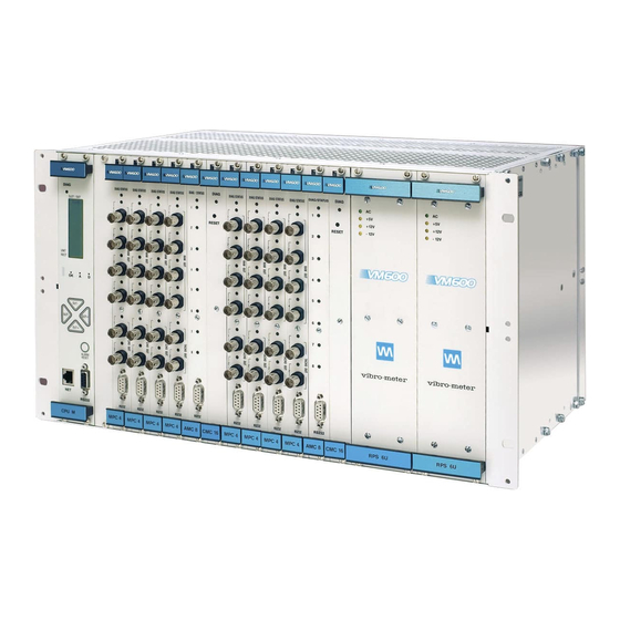
2- RPS6U rack power supply (ABE04x only) When an AC-input version of the RPS6U is installed in a VM600 rack, the optional ASPS auxiliary sensor power supply can be used to replace external power supplies such as the APF19x 24 V power supplies. - Page 28 Further information on the condition monitoring system hardware can be found in the VM600 condition monitoring system (CMS) hardware manual. Figure 1-1 Figure 1-2 show front and rear views of a typical VM600 (6U) rack containing machinery protection system (MPS) hardware. VM600 MPS hardware manual (standard version) MAMPS-HW/E Edition 17...
- Page 29 RPS6U card rack power supplies Figure 1-1: Front-view drawing of an example MPS system in a VM600 MPS system (ABE040 rack) featuring MPC4 / IOC4T card pairs VM600 MPS hardware manual (standard version) MAMPS-HW/E Edition 17 - February 2018...
- Page 30 Figure 1-2: Rear-view drawing of an example MPS system in a VM600 MPS system (ABE040 rack) featuring MPC4 / IOC4T card pairs VM600 MPS hardware manual (standard version) MAMPS-HW/E Edition 17 - February 2018...
-
Page 31: Communicating With The Vm600 Mps
CPU card installed: • A VM600 rack without a CPUM card, also known as a stand-alone rack, is a MPS system that is not connected to a network. In a stand-alone rack, each MPC4 and AMC8 card must be configured in turn using an RS-232 link to a computer running one of the VM600 MPS software packages (MPS1 or MPS2). - Page 32 Communicating with the VM600 MPS NOTE: A VM600 MPS in a 19″ system rack (ABE04x) containing a CPUM card can implement specific rack security features in order to limit the functionality of the MPS that are available via the CPUM to Ethernet-based connections, such as the VM600 MPSx software, the CPUM Configurator software or a Modbus TCP connection.
- Page 33 Communicating with the VM600 MPS Signal connections Rear of VM600 (ABE04x) rack Backplane Front of VM600 (ABE04x) rack Computer Ethernet RS-232 Modbus Figure 1-3: Methods of communicating with a VM600 MPS system VM600 MPS hardware manual (standard version) MAMPS-HW/E Edition 17 - February 2018...
- Page 34 INTRODUCTION Communicating with the VM600 MPS THIS PAGE INTENTIONALLY LEFT BLANK VM600 MPS hardware manual (standard version) MAMPS-HW/E Edition 17 - February 2018...
-
Page 35: Overview Of Vm600 Mps Hardware
2.1.1 VM600 system rack – 19" rack with a height of 6U (ABE04x) A VM600 MPS can be housed in a 19 inch rack (84TE) with a height of 6U (6HE), known as the VM600 system rack. Two types of this rack exist: the ABE040 and the ABE042. These are identical, except for the position of the rack mounting brackets. - Page 36 OVERVIEW OF VM600 MPS HARDWARE Racks Front view (PS2) (PS1) Rear view Side view Front Figure 2-1: Views of a typical ABE040 rack with several cards installed (machinery protection cards only) VM600 MPS hardware manual (standard version) MAMPS-HW/E Edition 17 - February 2018...
-
Page 37: Slot Number Coding For Cards In The Rear Of An Abe04X Rack
2-3). The result of the comparison is typically displayed on the SLOT ERROR LED on the cards panel: • If the codes are identical, the LED is green. • If the codes are not identical, the LED is red. VM600 MPS hardware manual (standard version) MAMPS-HW/E Edition 17 - February 2018... - Page 38 Slot number comparator (1) A = B: LED is green. (2) A ≠ B: LED is red. Figure 2-3: Slot number comparator and SLOT ERROR LED VM600 MPS hardware manual (standard version) MAMPS-HW/E Edition 17 - February 2018...
-
Page 39: Vm600 Slimline Rack - 19" Rack With A Height Of 1U (Abe056)
2.1.3 VM600 slimline rack – 19" rack with a height of 1U (ABE056) A VM600 MPS can be housed in a slimline 19 inch rack (84TE) with a height of 1U (1HE), known as the VM600 slimline rack. This type of rack is an ABE056. An example of a MPS... -
Page 40: Slot Number Coding For Cards In The Rear Of An Abe056 Rack
2-4, is correct and is compatible with earlier versions of the ABE056 rack. The equivalent “Rear view” drawing used in some earlier versions of the VM600 MPS hardware manual was incorrect, so it appears that the DC power supply input connector wiring has changed, but it has not. -
Page 41: Mpc4 Machinery Protection Card (Abe04X And Abe056)
This connector can be used to configure an MPC4 card in a stand-alone rack. 9-pin D-sub This is done via an interface cable from a computer running one of the VM600 MPS software packages (MPS1 or MPS2). See Figure 2-6 for details of the interface cable. - Page 42 Current input: 0.3245 V/mA. * Off – Channel not configured (“Sensor Connected” set to “No” in the VM600 MPSx software) or card not configured. * Green (continuous) – Signal input to the channel is valid and there are no active alarms.
-
Page 43: Ioc4T Input/Output Card (Abe04X And Abe056)
IOC4T is installed in the correct slot of the rack: Green – The card is in the correct slot Red – Slot number mismatch. Figure 2-8: IOC4T panel (rear of ABE04x and ABE056 racks) VM600 MPS hardware manual (standard version) MAMPS-HW/E Edition 17 - February 2018... -
Page 44: Amc8 Analog Monitoring Card (Abe04X And Abe056)
This connector can be used to configure an AMC8 card in a stand-alone rack. 9-pin D-sub This is done via an interface cable from a computer running one of the VM600 MPS software packages (MPS1 or MPS2). See Figure 2-6 for details of the interface cable. - Page 45 2 to 8. Operation as per measurement channel 1. RS-232 connector Can be used to configure an AMC8 card in a stand-alone rack (without CPUM card) using the VM600 MPSx software. Notes: See also Table 5-1 Table 5-2 for further information on the behaviour of AMC8 card LEDs.
-
Page 46: Cpum Modular Cpu Card (Abe04X Only)
Figure 2-11 for details on the physical appearance of this card. 2.7 IOCN input/output card (ABE04x only) Figure 2-12 for details on the physical appearance of this card. VM600 MPS hardware manual (standard version) MAMPS-HW/E Edition 17 - February 2018... - Page 47 MPC4 and AMC8 cards in the rack ‘NET’ connector (8P8C (RJ45)) for primary Ethernet connection, ‘RS232’ connector (D-sub (DE-09)) for primary serial used for VM600 rack connection, used for VM600 rack configuration and configuration and communications communications, and Modbus TCP communications...
- Page 48 Modbus RTU communications – Group B. Supports RS-485 (2-wire or 4-wire) communications. ‘1’ Ethernet connector (8P8C (RJ45)) for primary Ethernet connection, used for VM600 rack configuration and communications, and Modbus TCP communications. Note: The primary Ethernet connection can be routed to either the ‘NET’...
-
Page 49: Rlc16 Relay Card (Abe04X And Abe056)
(b) shows the appearance of the panel when the three mating connectors are inserted. Connector J1 Connector J2 Connector J3 Figure 2-13: RLC16 panel (rear of ABE04x and ABE056 racks) VM600 MPS hardware manual (standard version) MAMPS-HW/E Edition 17 - February 2018... -
Page 50: Irc4 Intelligent Relay Card (Abe04X And Abe056)
* Red – Slot number mismatch or HW error. (Same function as the SLOT ERROR LED on other cards.) (Not used) IRC 4 IRC 4 Figure 2-14: IRC4 panel (rear of ABE04x and ABE056 racks) VM600 MPS hardware manual (standard version) MAMPS-HW/E Edition 17 - February 2018... -
Page 51: Rps6U Rack Power Supply (Abe04X Only)
The improved RPS6U rack power supply (330 W) can supply a full rack of cards, such as 12 x MPC4/IOC4T card pairs or 12 x XMx16/XIO16T card pairs. This means that a VM600 rack with two RPS6U power supplies (330 W) installed and operating non-redundantly is usually only necessary for applications where the operating environment requires RPS6U output power derating. -
Page 52: Identifying Different Versions Of The Rps6U Rack Power Supply
For an existing VM600 system, it is important to note that simply replacing an old RPS6U rack power supply (300 W) with a new one (330 W) should not be used as a way to increase the maximum output power available in order to add more cards to the rack –... -
Page 53: Rps6U Rack Power Supply And Vm600 Card Considerations
50°C (122°F). When two RPS6U rack power supplies operate redundantly to supply power to the cards in a VM600 rack, the maximum current available for use by the cards is limited to the current available from a single RPS6U power supply. -
Page 54: Support Rack Power Supply Redundancy
When two RPS6U rack power supplies operate non-redundantly to supply power to the cards in a VM600 rack, the maximum current available for use by the cards is limited to approximately 125% (x 1.25) the current available from a single RPS6U power supply. -
Page 55: Racks Supporting External Mains Power-Supply System Redundancy
VM600 rack, so that should one power supply fail, then the other power supply can continue to supply power the cards in the rack. For information on the associated rear panels that can be used by a VM600 rack with or without rack power supply redundancy, see 2.10.9.1, 2.10.9.2, 2.10.9.3, 2.10.9.5, 2.10.9.6, 2.10.9.7, 2.10.9.8, 2.10.9.9,... -
Page 56: Front Panels
RPS6U rack power supply: power supply AC-input version (left) and DC-input version (right) Figure 2-15: Front panels for the different versions of the RPS6U rack power supply VM600 MPS hardware manual (standard version) MAMPS-HW/E Edition 17 - February 2018... -
Page 57: Associated Rear Panels
(The front panel of the DC-input versions of the RPS6U rack power supply is shown in Figure 2-15.) A VM600 rack power supply solution using this DC-input panel is intended for use with one DC-mains supply, that is, a non-redundant external power-supply system. vibro meter... - Page 58 DC-input panel with a common input (special earth terminal) This rear panel has one DC input with a screw-terminal connector that provides a common input to DC-input versions of the RPS6U power supplies in a VM600 rack. It also provides a special earth terminal (identified as M.A.L.T.).
- Page 59 (The front panel of the DC-input versions of the RPS6U rack power supply is shown in Figure 2-15.) A VM600 rack power supply solution using this DC-input panel is intended for use with two DC-mains supplies, that is, a non-redundant external power-supply system. vibro meter...
- Page 60 (The front panel of the DC-input versions of the RPS6U rack power supply is shown in Figure 2-15.) A VM600 rack power supply solution using this DC-input panel is intended for use with two DC-mains supplies arranged as a redundant external power-supply system (see 2.10.7 Racks supporting external mains power-supply system...
- Page 61 AC-input panel with a common input is the standard associated rear panel. This rear panel has one AC input (120/230 V ) with mains socket and on/off switch that provides a common input to the AC-input version of the RPS6U power supplies in a VM600 rack. Figure 2-20 shows: a.
- Page 62 (The front panel of the AC-input version of the RPS6U rack power supply is shown in Figure 2-15.) A VM600 rack power supply solution using this AC-input panel is intended for use with one AC-mains (120/230 V ) supply, that is, a non-redundant external power-supply system.
- Page 63 (The front panel of the AC-input version of the RPS6U rack power supply is shown in Figure 2-15.) A VM600 rack power supply solution using this AC-input panel is intended for use with one AC-mains (120/230 V ) supply, that is, a non-redundant external power-supply system.
- Page 64 (The front panel of the AC-input version of the RPS6U rack power supply is shown in Figure 2-15.) A VM600 rack power supply solution using this AC-input panel is intended for use with two AC-mains (120/230 V ) supplies, that is, a non-redundant external power-supply system.
- Page 65 (a) Rear panel (Rear panel (Internal to connections) VM600 rack) (b) Wiring details Figure 2-23: AC-input (120/230 V ) panel with individual inputs (mains sockets and on/off switches) VM600 MPS hardware manual (standard version) MAMPS-HW/E Edition 17 - February 2018...
- Page 66 (The front panel of the AC-input version of the RPS6U rack power supply is shown in Figure 2-15.) A VM600 rack power supply solution using this AC-input panel is intended for use with two AC-mains (120/230 V ) supplies, that is, a non-redundant external power-supply system.
- Page 67 (The front panel of the AC-input version of the RPS6U rack power supply is shown in Figure 2-15.) A VM600 rack power supply solution using this AC-input panel is intended for use with two AC-mains (120/230 V ) supplies, that is, a non-redundant external power-supply system.
- Page 68 This rear panel has two AC inputs (120 V only) with mains sockets and on/off switches that provide a common input to the AC-input version of the RPS6U power supplies in a VM600 rack. Figure 2-26 shows: a.
- Page 69 (a) Rear panel (Rear panel (Internal to connections) VM600 rack) (b) Wiring details Figure 2-26: AC-input (120 V only) panel with individual inputs supporting external mains power supply redundancy VM600 MPS hardware manual (standard version) MAMPS-HW/E Edition 17 - February 2018...
- Page 70 This rear panel has two AC inputs (230 V only) with mains sockets and on/off switches that provide a common input to the AC-input version of the RPS6U power supplies in a VM600 rack. Figure 2-27 shows: a.
- Page 71 (a) Rear panel (Rear panel (Internal to connections) VM600 rack) (b) Wiring details Figure 2-27: AC-input (230 V only) panel with individual inputs supporting external mains power supply redundancy VM600 MPS hardware manual (standard version) MAMPS-HW/E Edition 17 - February 2018...
- Page 72 (The front panel of the AC-input version of the RPS6U rack power supply is shown in Figure 2-15.) A VM600 rack power supply solution using this combined AC-input and DC-input panel is intended for use with one AC-mains (120/230 V ) supply and one DC-mains supply, that is, a non-redundant external power-supply system.
- Page 73 DATA MATRIX (a) Rear panel (Rear panel (Internal to connections) VM600 rack) (b) Wiring details Figure 2-28: Combined AC-input (120/230 V ) and DC-input panel with individual inputs VM600 MPS hardware manual (standard version) MAMPS-HW/E Edition 17 - February 2018...
-
Page 74: Power Supply Check Relay
RPS6U rack power supply or supplies to the VM600 system rack (ABE04x) backplane. The connector for the power supply check relay is available at the rear of the rack, on the rear panel associated with the RPS6U power supply or supplies. - Page 75 COM and NC contacts. 2- When only the first RPS6U (PS1) is installed (slots 18 to 20): • Jumper J16 must be left open • Jumper J17 must be closed. VM600 MPS hardware manual (standard version) MAMPS-HW/E Edition 17 - February 2018...
-
Page 76: Power Supply Labelling
(see Figure 2-30). • For earlier versions of VM600 system racks, a VM600SYS label on a rear panel provides the specifications for the RPS6U power supply inputs and additional information about the VM600 system such as order number (see Figure 2-31). - Page 77 Vdc - GND - NC DC OUT #2 24Vdc - 1.1A Vdc - GND - NC Figure 2-32: ASPS intended for use with an RPS6U (AC-mains supply input) VM600 MPS hardware manual (standard version) MAMPS-HW/E Edition 17 - February 2018...
- Page 78 (ABE056) data sheet). The RPS1U rack power supply must be with an appropriate connection panel at the rear of the VM600 rack in order to allow the connection of external AC-mains or DC-mains power to the rack. See also 8.3 Rack safety...
- Page 79 Normally open (NO) Common (COM) –12 V +12 V Figure 2-33: Operation of the power supply check relay for the RPS1U power supply installed in a VM600 rack (ABE056) VM600 MPS hardware manual (standard version) MAMPS-HW/E Edition 17 - February 2018...
-
Page 80: Power Supply Labelling
RPS1U rack power supply (ABE056 only) 2.11.2 Power supply labelling Information regarding the DC and AC inputs for the RPS1U power supply used by the VM600 slimline rack (ABE056) is available on labels on the top and rear of the rack (see Figure 2-34). -
Page 81: General System Description
System elements 3 GENERAL SYSTEM DESCRIPTION 3.1 System elements In order to gain an understanding of the operation of a VM600 machinery protection system (MPS), it is necessary to consider the interaction of the principal elements making up this system, namely: 1- ABE04x (19"... - Page 82 MPC4 / IOC4T card pairs over the VME bus. NOTE: The safety version of the MPC4 card (MPC4SIL) does not have a VME bus interface so it cannot communicate with a CPUM or any other cards in a VM600 rack (see 4 MPC4 / IOC4T card pair).
- Page 83 CPUM Card interface. Slot X (Front Cage) Slots 0+1 (Front Cage) Figure 3-1: Block diagram of cards in a VM600 MPS (configuration based on MPC4 / IOC4T card pairs) VM600 MPS hardware manual (standard version) MAMPS-HW/E Edition 17 - February 2018...
-
Page 84: Rack With Amc8 / Ioc8T Card Pairs
This card handles the management of signals, alarm levels, signal processing and so on. The user is able to modify parameters concerning these operations by using one of the VM600 MPS software packages (MPS1 or MPS2), from Meggitt Sensing Systems’ Vibro-Meter product line. - Page 85 CPUM Card AMC8 Card Slots 0+1 (Front Cage) Slot X (Front Cage) Figure 3-2: Block diagram of cards in a VM600 MPS (configuration based on AMC8 / IOC8T card pairs) VM600 MPS hardware manual (standard version) MAMPS-HW/E Edition 17 - February 2018...
-
Page 86: Vm600 6U 19" Rack Backplane (Abe04X)
3.4 VM600 6U 19" rack backplane (ABE04x) 3.4.1 General overview The VM600 MPS using a 6U 19" system rack (ABE04x) with a custom-designed backplane combines features of a VME backplane and other special features to support Meggitt Sensing Systems’ Vibro-Meter product line (see... - Page 87 24-bit address and 16-bit data transfers between cards in the rack. NOTE: The safety version of the MPC4 card (MPC4SIL) does not have a VME bus interface so it cannot communicate with a CPUM or any other cards in a VM600 rack (see 4 MPC4 / IOC4T card pair).
- Page 88 IOC card by the MPC4 or AMC8 card Figure 3-4: Diagram of VM600 rack (ABE04x) backplane showing the arrangement of the connectors VM600 MPS hardware manual (standard version) MAMPS-HW/E Edition 17 - February 2018...
-
Page 89: Tacho Bus
MPC4 card (MPC #B). This technique is known as using “remote" speed signals. The VM600 MPSx software ensures that two or more speed signals are not sent to the same Tacho Bus line. A signal on a given Tacho Bus line can be used by more than one card. - Page 90 GENERAL SYSTEM DESCRIPTION VM600 6U 19" rack backplane (ABE04x) VM600 MPS hardware manual (standard version) MAMPS-HW/E Edition 17 - February 2018...
-
Page 91: Open Collector Bus
IRC4 or RLC16 IRC4 or RLC16 location locations Figure 3-6: Rear view of rack showing the six dedicated OC Buses and the Raw Bus (top) VM600 MPS hardware manual (standard version) MAMPS-HW/E Edition 17 - February 2018... - Page 92 AMC8 / IOC8T card pair) to an OC Bus line is done under software control. NOTE: Refer to the relevant manual for further information: VM600 MPS1 software manual or VM600 MPS2 software manual. The attribution of a specific line on the OC Bus to a specific relay on the RLC16 is done by setting jumpers on the RLC16.
- Page 93 = {3, 5, 7, 9, 11 or 13} Notes 1. Specific alarms (A+, D− and so on) are attributed to the OC Bus lines using the VM600 MPSx software. Table 9-4 for information on the normal state of the control signal.
-
Page 94: Raw Bus
(that is, the XIO16T hardware is fully software configurable). IOC4T #A IOC4T #B IOC16T #A Jumper Jumper Switches matrix matrix Figure 3-8: Use of the Raw Bus to transfer analog signals between cards VM600 MPS hardware manual (standard version) MAMPS-HW/E Edition 17 - February 2018... - Page 95 • A DC output from the IOC8T is connected to a dynamic input channel of the IOC16T using external cabling • Modbus is used to communicate the analog values (which requires that a CPUM card is also installed in the rack). VM600 MPS hardware manual (standard version) MAMPS-HW/E Edition 17 - February 2018...
-
Page 96: Vm600 1U 19" Rack Backplane (Abe056)
VM600 1U 19" rack backplane (ABE056) 3.5 VM600 1U 19" rack backplane (ABE056) The VM600 MPS using a 1U 19" slimline rack (ABE056) with a custom-designed backplane contains a similar version of the backplane currently used with the standard 19" 6U (ABE04x) rack described in 3.4 VM600 6U 19"... -
Page 97: Part I: Functional Description Of Vm600 Mps System
Part I: Functional description of VM600 MPS system VM600 MPS hardware manual (standard version) MAMPS-HW/E Edition 17 - February 2018... - Page 98 THIS PAGE INTENTIONALLY LEFT BLANK...
-
Page 99: Mpc4 / Ioc4T Card Pair
MPC4 / IOC4T card pairs and RLC16 relay cards. The standard MPC4 has a VME-compatible slave interface and is software configurable via RS-232 (on the panel of the MPC4 card) or via VME for a networked VM600 rack. It also supports all processing modes (see Table 7-1). -
Page 100: Identifying Different Versions Of The Mpc4 Card
• MPC4SIL is used to refer to safety version of the MPC4 card. NOTE: Refer to the relevant manual for further information: VM600 MPS1 software manual or VM600 MPS2 software manual. VM600 MPS hardware manual (standard version) MAMPS-HW/E Edition 17... - Page 101 (a) Standard version and separate circuits (b) Safety version of the MPC4 card version of the MPC4 card (that is, the MPC4SIL) Figure 4-1: Different versions of the MPC4 card VM600 MPS hardware manual (standard version) MAMPS-HW/E Edition 17 - February 2018...
-
Page 102: General Block Diagram
The IRC4 card contains 8 relays that can be combined as 4 DPDT or 8 SPDT and has a terminal strip with 32 screw terminals (2 strips each having 16 terminals). VM600 MPS hardware manual (standard version) MAMPS-HW/E Edition 17... - Page 103 Rack backplane Abbreviations: ADC = Analog-to-digital converter, AR = Alarm Reset, DAC = Digital-to-analog converter, IRC4 2 x screw Relays (Rear card cage) DB = Danger Bypass, DSP = Digital signal processor, terminal strip EMC = Electromagnetic compatibility, IP = Industry pack, I/P = Input, Intelligent relay card with 4 DPDT or 8 SPDT (J1, J2) JS = Jumper selectable, OC = Open Collector, TM = Trip Multiply,...
-
Page 104: Overview Of Mpc4 Operation
The “processed values” include the two “monitored” values. They also include the OK levels of the sensors. The “speed values” are also monitored and include the OK value of the sensor. Figure 4-3: Operation of MPC4 machinery protection card VM600 MPS hardware manual (standard version) MAMPS-HW/E Edition 17 - February 2018... -
Page 105: Sensor Signal Conditioning
CH4 terminals on the IOC4T) deliver conditioned signals to the MPC4 card. These conditioned inputs are composed of AC signals with or without a DC component. Typically, VM600 MPS hardware manual (standard version) MAMPS-HW/E Edition 17 - February 2018... - Page 106 The signal then undergoes a first stage of amplification/attenuation (Figure 4-4, Ref. 1). The DC and AC components of the signal are processed by two separate paths (Figure 4-4, Ref. 2). These are described below. VM600 MPS hardware manual (standard version) MAMPS-HW/E Edition 17 - February 2018...
- Page 107 Voltage-based input signal Two types of voltage-based signals (AC+DC) can be considered, differing only in the meaning of the DC component: 1- DC component is used for OK line check VM600 MPS hardware manual (standard version) MAMPS-HW/E Edition 17 - February 2018...
-
Page 108: Speed Signal Inputs
(HI) and the unused sensor power supply terminal (PS). This is configured automatically by the VM600 MPSx software when the Sensor Power Supply field is set to No Supply. This technique enables open circuits to be detected, but not short circuits. - Page 109 VT+ = −7 V + ⅔ ( (−15 V) − (−7 V) ) = −7 V + ⅔ (−8 V) = −12.33 V VT− = −7 V + ⅓ ( (−15 V) − (−7 V) ) = −7 V + ⅓ (−8 V) = −9.66 V VM600 MPS hardware manual (standard version) MAMPS-HW/E Edition 17...
-
Page 110: Analog Outputs
RAW 3L, and RAW 4H and RAW 4L) are accessible on the IOC4T card. The same bandwidth and accuracy specifications apply as per the BNC outputs on the MPC4 panel. VM600 MPS hardware manual (standard version) MAMPS-HW/E Edition 17 - February 2018... -
Page 111: Dc Outputs (Ioc4T)
DC output signal range can be either 4 to 20 mA or 0 to 10 V. Outputs are configured using the VM600 MPS software. For example, a 4 to 20 mA DC output corresponding to a 0 to 500 µm signal. -
Page 112: Rectification Techniques
2. True Peak or True Peak-to-Peak values can be calculated for proximity probe measuring chains. 3. The RMS value is the standard calculation for accelerometer-based measuring chains. VM600 MPS hardware manual (standard version) MAMPS-HW/E Edition 17 - February 2018... -
Page 113: Alarm Monitoring
∆t ≥ 3 s A− D− Time A+ status Normal Alarm Normal unlatched A+ status Normal Alarm Normal latched Time Alarm Reset Figure 4-6: Illustration of unlatched and latched alarms VM600 MPS hardware manual (standard version) MAMPS-HW/E Edition 17 - February 2018... -
Page 114: Logical Combinations Of Alarms
4.6.2 Logical combinations of alarms The MPS allows logical combinations of alarms to be configured under software control. NOTE: Refer to the relevant manual for further information: VM600 MPS1 software manual or VM600 MPS2 software manual. Two types of alarm combination functions exist: •... - Page 115 >1 of 3 Ch.3, Out.2 Danger− Advanced Function 2 Speed Ch.1, Alert+ Basic Function 3 Speed Ch.2, Alert+ Figure 4-7: Example showing basic and advanced logic functions VM600 MPS hardware manual (standard version) MAMPS-HW/E Edition 17 - February 2018...
-
Page 116: Adaptive Monitoring
Up to 10 multiplier coefficients can be configured (for example, 0.5, 0.8, 1.2 and so on, in Figure 4-8). These coefficients can be chosen in the range 0.1 to 5.0, in steps of 0.1. VM600 MPS hardware manual (standard version) MAMPS-HW/E Edition 17 - February 2018... - Page 117 Speed Figure 4-8: Illustration of adaptive monitoring technique In order to use the Adaptive Monitoring function, it must first be activated using the VM600 MPSx software (using the Adaptive Monitoring property sheet of the relevant Processed Output tab for the appropriate Processing Channel node).
-
Page 118: Direct Trip Multiply
Speed Figure 4-9: Illustration of direct Trip Multiply technique In order to use the Trip Multiply function, it must first be activated using the VM600 MPSx software (using the Adaptive Monitoring property sheet of the relevant Processed Output tab for the appropriate Processing Channel node). -
Page 119: Danger Bypass Function
• For a speed channel, the error bit (Err), OK system check (SOK) and alarm (A+, A−) flags are all forced to a normal state. The sensor bypassed (SBP) flag and the invalid output flags are also set active (=1). VM600 MPS hardware manual (standard version) MAMPS-HW/E Edition 17 - February 2018... - Page 120 NOTE: When an MPC4 card is configured (using the VM600 MPS software), the channel inhibit function is automatically de-activated for any channels where it is active. The status of the channel inhibit function for the individual channels of an MPC4 card can be used as an input to a basic function (see 4.6.2 Logical combinations of...
-
Page 121: System Self-Checks
100 ms. NOTE: The behaviour of the OK system checking is the same above and below the configured OK levels. VM600 MPS hardware manual (standard version) MAMPS-HW/E Edition 17 - February 2018... -
Page 122: Built-In Test Equipment (Bite)
In practice, it can take up to 350 ms (“confirmation time” + “response time”) after an input signal goes outside the configured OK levels before it is confirmed and acted upon in a VM600 system as an OK System failure. When there is an OK System failure on an MPC4 card: •... -
Page 123: Mpc4 Power-Up Sequence
In this way no glitches are produced on the VME bus power, address or data pins. Once the rest of the pins (including the standard +5 V supply) make contact, no further power is drawn from the +5 V pre-charge supply. VM600 MPS hardware manual (standard version) MAMPS-HW/E Edition 17 - February 2018... -
Page 124: Operation Of Leds On Mpc4 Panel
Danger Bypass (DB) function active Yellow (continuous) Trip Multiply (TM) function active Normal card operation – MPC4 configuration is running correctly with Green (continuous) no alarms and no errors VM600 MPS hardware manual (standard version) MAMPS-HW/E Edition 17 - February 2018... -
Page 125: Individual Status Indicator Leds For Measurement Channels
Danger level or above the upper Danger level. That is, either there was a previously active processing alarm that has not been reset or there is a currently active processing alarm. VM600 MPS hardware manual (standard version) MAMPS-HW/E Edition 17 - February 2018... - Page 126 Normal channel operation – channel is configured and signal input is Green (continuous) valid (not exceeding lower or upper “OK Levels”). That is, there are no active single-channel processing or dual-channel processing alarms. VM600 MPS hardware manual (standard version) MAMPS-HW/E Edition 17 - February 2018...
-
Page 127: Individual Status Indicator Leds For Speed Channels
Normal channel operation – channel is configured and signal input is Green (continuous) valid (not exceeding lower or upper “OK Levels”). That is, there are no active processing alarms. VM600 MPS hardware manual (standard version) MAMPS-HW/E Edition 17 - February 2018... - Page 128 MPC4 / IOC4T CARD PAIR Operation of LEDs on MPC4 panel THIS PAGE INTENTIONALLY LEFT BLANK VM600 MPS hardware manual (standard version) MAMPS-HW/E Edition 17 - February 2018...
-
Page 129: Amc8 / Ioc8T Card Pair
The IRC4 card contains 8 relays that can be combined as 4 DPDT or 8 SPDT and has a terminal strip with 32 screw terminals (2 strips each having 16 terminals). VM600 MPS hardware manual (standard version) MAMPS-HW/E Edition 17... - Page 130 Rack backplane IRC4 (Rear card cage) Relays Intelligent relay card with 4 DPDT or 8 SPDT RLC16 (Rear card cage) Relays Relay card with 16 change-over contacts Channel 1 Isolated Analog to Sensor digital interface + type interface converter floating PS switching Meas.
-
Page 131: Overview Of Amc8 / Ioc8T Operation
Processed value Alarms “Multi- Processed value channel” processing / monitoring Alarms (4 channels) Processed value Alarms / OK Processed value Figure 5-2: Operation of AMC8 / IOC8T card pair VM600 MPS hardware manual (standard version) MAMPS-HW/E Edition 17 - February 2018... -
Page 132: Sensor Signal Conditioning
This function monitors the OK levels for the sensor to check for hardware problems (for example, faulty sensor or signal conditioner, or defective transmission line). 5.8 System self-checks. VM600 MPS hardware manual (standard version) MAMPS-HW/E Edition 17 - February 2018... -
Page 133: Inputs And Outputs
It is not possible to have a mixture of current-based and voltage-based outputs. Outputs are configured using the VM600 MPS software. For example, a 4 to 20 mA output corresponding to a 25 to 100°C signal. The actual value of a DC output can go outside the specified output signal range, depending on the processed value (signal). -
Page 134: Multi-Channel Processing Functions
The time period can be set under software control to a value between 0.1 and 10.0 seconds. The output is updated at this rate. 5.6 Linearity compensation The VM600 MPS software allows linearity compensation for thermocouples and RTD devices. For linear compensation, an offset and sensitivity value can be defined. -
Page 135: Alarm Monitoring
∆t ≥ 3 s A− D− Time A+ status Normal Alarm Normal unlatched A+ status Normal Alarm Normal latched Time Alarm Reset Figure 5-3: Illustration of unlatched and latched alarms VM600 MPS hardware manual (standard version) MAMPS-HW/E Edition 17 - February 2018... -
Page 136: Logical Combinations Of Alarms
5.7.2 Logical combinations of alarms The MPS allows logical combinations of alarms to be configured under software control. NOTE: Refer to the relevant manual for further information: VM600 MPS1 software manual or VM600 MPS2 software manual. Two types of alarm combination functions exist: •... -
Page 137: Danger Bypass Function
The Danger Bypass function is activated when a low (0 V) external signal is applied to the Danger Bypass input on the IOC8T card. See also 5.7.4 Channel inhibit function. VM600 MPS hardware manual (standard version) MAMPS-HW/E Edition 17 - February 2018... -
Page 138: Channel Inhibit Function
(SBP) flag is also set inactive. NOTE: When an AMC8 card is configured (using the VM600 MPS software), the channel inhibit function is automatically de-activated for any channels where it is active. The status of the channel inhibit function for the individual channels of an AMC8 card can be used as an input to a basic function (see 5.7.2 Logical combinations of... -
Page 139: System Self-Checks
The actual time delay depends on the processor load of the card but is less than 100 ms. NOTE: The behaviour of the OK system checking is the same above and below the configured OK levels. VM600 MPS hardware manual (standard version) MAMPS-HW/E Edition 17 - February 2018... -
Page 140: Built-In Self Test (Bist)
• Line resistance mismatch (for 3-wire RTD measurements) • Correct setting of jumper J805. Errors detected by the BIST are used to set flags that can then be used by the VM600 MPS software to switch relays and so on. -
Page 141: Amc8 Power-Up Sequence
In this way no glitches are produced on the VME bus power, address or data pins. Once the rest of the pins (including the standard +5 V supply) make contact, no further power is drawn from the +5 V pre-charge supply. VM600 MPS hardware manual (standard version) MAMPS-HW/E Edition 17 - February 2018... -
Page 142: Operation Of Leds On Amc8 Panel
Normal card operation – AMC8 configuration is running correctly with Green (continuous) no alarms and no errors VM600 MPS hardware manual (standard version) MAMPS-HW/E Edition 17 - February 2018... -
Page 143: Individual Status Indicator Leds For Measurement Channels
Normal channel operation – channel is configured and signal input is Green (continuous) valid (not exceeding lower or upper “OK Levels”). That is, there are no active single-channel processing or multi-channel processing alarms. VM600 MPS hardware manual (standard version) MAMPS-HW/E Edition 17 - February 2018... - Page 144 AMC8 / IOC8T CARD PAIR Operation of LEDs on AMC8 panel THIS PAGE INTENTIONALLY LEFT BLANK VM600 MPS hardware manual (standard version) MAMPS-HW/E Edition 17 - February 2018...
-
Page 145: Cpum / Iocn Card Pair
The CPUM is a modular CPU (central processing unit) card that acts as “rack controller” in a networked VM600 system. Depending on system requirements, the CPUM can be used either alone in the rack (installed in the front card cage) or in conjunction with the associated IOCN input/output card (installed in slot 0 of the rear card cage, directly behind the CPUM). -
Page 146: Vm600 Mps Rack (Cpum) Security
A diagnostic LED (named DIAG) on the panel of the CPUM indicates the CPUM card status, such as normal operation and whether VM600 MPS rack (CPUM) security is being used. The CPUM card’s panel also contains an LCD display for showing the level of a selected monitored output in bar-graph and digital form. -
Page 147: Block Diagrams
Block diagrams thereby reducing the possibility of interference in the operation of the MPS and the machinery being monitored. NOTE: Refer to the VM600 MPS1 software manual for further information on VM600 MPS rack (CPUM) security. 6.4 Block diagrams Figures... -
Page 148: Serial Port Naming
CPU module 1: PFM-541I or equivalent (J2) CPUM panel Figure 6-1: Block diagram of CPUM card fitted with the PFM-541I or equivalent CPU module (PNR 200-595-076-HHh or later) VM600 MPS hardware manual (standard version) MAMPS-HW/E Edition 17 - February 2018... - Page 149 CPU module 1: MSM586SEN or equivalent (J2) CPUM panel Figure 6-2: Block diagram of CPUM card fitted with the MSM586SEN or equivalent CPU module (PNR 200-595-075-HHh or earlier) VM600 MPS hardware manual (standard version) MAMPS-HW/E Edition 17 - February 2018...
- Page 150 6P6C (RJ11/RJ25) (J9) (SERIAL_B) 6P6C (RJ11/RJ25) (J10) COM1 COM2 COM3 8P8C (RJ45) (J1) 8P8C (RJ45) (J2) ETH0 ETH1 (J11) IOCN panel Figure 6-3: Block diagram of IOCN card VM600 MPS hardware manual (standard version) MAMPS-HW/E Edition 17 - February 2018...
-
Page 151: Operation Of Leds On Cpum Panel
The CPUM is operating normally and access to the CPUM card is allowed (CPUM Access Lock: Unlocked). Green (continuous) That is, VM600 MPS rack (CPUM) security is not being used. The CPUM is operating normally but access to the CPUM card is Green blinking slowly restricted (CPUM Access Lock: Locked). - Page 152 CPUM / IOCN CARD PAIR Operation of LEDs on CPUM panel THIS PAGE INTENTIONALLY LEFT BLANK VM600 MPS hardware manual (standard version) MAMPS-HW/E Edition 17 - February 2018...
-
Page 153: Processing Modes And Applications
The MPS is generally fully configured in the factory before delivery and can be employed as is. In some cases one of the VM600 MPS software packages (MPS1 or MPS2) can be used to allow further configuration of system parameters, or to reconfigure the MPS if it is extended by the addition of MPC, IOC or relay cards (such as the RLC16). - Page 154 MPC4 card (standard and the separate circuits versions), it is not available for the MPC4SIL card (safety version). NOTE: Refer to the VM600 safety manual for further information. VM600 MPS hardware manual (standard version) MAMPS-HW/E Edition 17 - February 2018...
-
Page 155: Broad-Band Absolute Bearing Vibration
Absolute vibration is generally measured with seismic transducers mounted on a machine bearing housing or other mechanical structure. A number of transducers (and matching signal conditioners) are available from Meggitt Sensing Systems’ Vibro-Meter product line for this purpose. The following front-end components are the most commonly used: •... - Page 156 When one or two integrators are used in the processing, the broad-band filtering stage must include at least one high-pass filter, having a minimum slope of 12 dB/octave. VM600 MPS hardware manual (standard version) MAMPS-HW/E Edition 17 - February 2018...
-
Page 157: Tracking (Narrow-Band Vibration Analysis)
For a given harmonic, the processing outputs the amplitude and phase. However, the phase is available only if the 1/REV input is present. The tracking processing is able to operate in the frequency range 0.1 Hz to 10 kHz. VM600 MPS hardware manual (standard version) MAMPS-HW/E Edition 17 - February 2018... -
Page 158: Shaft Relative Vibration With Gap Monitoring
Vibration processing is done with a 10 kHz bandwidth and DC processing with a 1 Hz bandwidth. The low-pass cut-off frequency can be set between 250 Hz and 10 kHz using the VM600 MPSx software. VM600 MPS hardware manual (standard version) MAMPS-HW/E... -
Page 159: Shaft Absolute Vibration
The processing outputs one of two values per channel: either rectified displacement or rectified velocity. RMS, Mean, True Peak or True Peak-Peak rectification are possible on the AC displacement or velocity value. The averaging time T can be configured using the VM600 MPS software. 7.5 Shaft absolute vibration Description... - Page 160 (Channel 1 or Channel 3) CVxxx IQSxxx TQxxx Measurement channel for RS (Channel 2 or Channel 4) Figure 7-5: Typical measuring chain configurations for shaft absolute vibration measurement VM600 MPS hardware manual (standard version) MAMPS-HW/E Edition 17 - February 2018...
- Page 161 90° (that is, the output signal is 90° behind the input signal). AS = AB + RS (with sensors at the same location, AS = AB − RS (with sensors diametrically opposed, VM600 MPS hardware manual (standard version) MAMPS-HW/E Edition 17 - February 2018...
-
Page 162: Position Measurement
(maximum displacement) value as defined in ISO 7919-1. However, there are different methods of calculating S , defined as methods A, B and C in ISO 7919-1 Annex B. VM600 MPS hardware manual (standard version) MAMPS-HW/E Edition 17 - February 2018... - Page 163 VibroSmart VSV300 modules all use ISO 7919-1 method C to calculate the value of S However, since the actual signal processing implemented by VM600 MPC4 cards, VM600 XMV16 cards and VibroSmart VSV300 modules is different, the calculated values obtained from their respective S processing functions can be slightly different.
- Page 164 Peak Alarm level detector Y vibration value + alarms Relative shaft processing, Y input with gap Y gap value + alarms Figure 7-9: Block diagram showing S processing VM600 MPS hardware manual (standard version) MAMPS-HW/E Edition 17 - February 2018...
-
Page 165: Eccentricity Measurements
True Peak-to-Peak rectification used for continuous eccentricity measurement • Peak-to-Peak per Revolution rectification used for triggered eccentricity measurement. For this type of measurement, the 1/REV tacho input must be available. VM600 MPS hardware manual (standard version) MAMPS-HW/E Edition 17 - February 2018... -
Page 166: Shaft Relative Expansion
The relative expansion value can be several tens of millimetres, which is beyond the measuring range of a single proximity probe. For this reason, Meggitt Sensing Systems’ Vibro-Meter product line offers four types of measurement systems that offer an extended measuring range. -
Page 167: Shaft Collar Method
) in the operating range of probe 1. − ΔL = (GAP2 GAP2) in the operating range of probe 2. − Figure 7-11: Two proximity probes mounted near a shaft fitted with a collar VM600 MPS hardware manual (standard version) MAMPS-HW/E Edition 17 - February 2018... - Page 168 1 ∆L Expansion alarms Initial gap 2 Y position value Input 2 Y position alarms Alarm level detectors Figure 7-12: Block diagram showing processing for shaft collar method VM600 MPS hardware manual (standard version) MAMPS-HW/E Edition 17 - February 2018...
-
Page 169: Double Shaft Taper Method
) ] / 2sinα − − − where GAP is the initial gap value. Figure 7-13: Two proximity probes mounted near a shaft fitted with a double taper VM600 MPS hardware manual (standard version) MAMPS-HW/E Edition 17 - February 2018... - Page 170 Expansion alarms Initial gap 2 f(α Y position value Input 2 Y position alarms Alarm level detectors Figure 7-14: Block diagram showing processing for double shaft taper method VM600 MPS hardware manual (standard version) MAMPS-HW/E Edition 17 - February 2018...
-
Page 171: Single Shaft Taper Method
ΔG2 cosα) / sinα => − finally, ΔL = [ (GAP1 ) cosα ] / sinα GAP1 (GAP2 GAP2 − − − where GAP is the initial gap value. VM600 MPS hardware manual (standard version) MAMPS-HW/E Edition 17 - February 2018... - Page 172 ∆L Expansion alarms Initial gap 2 Y position value Input 2 Y position alarms Alarm level detectors Figure 7-16: Block diagram showing processing for single shaft taper method VM600 MPS hardware manual (standard version) MAMPS-HW/E Edition 17 - February 2018...
-
Page 173: Pendulum Method
(long arm of lever) Short arm of lever Head of pendulum (magnetic) Shaft collar Shaft Figure 7-17: A measuring system using a pendulum with magnetic head installed near a shaft collar VM600 MPS hardware manual (standard version) MAMPS-HW/E Edition 17 - February 2018... - Page 174 PROCESSING MODES AND APPLICATIONS Shaft relative expansion Block diagram Alarm Input Alarm level detector Initial Value Figure 7-18: Block diagram showing processing for pendulum method VM600 MPS hardware manual (standard version) MAMPS-HW/E Edition 17 - February 2018...
-
Page 175: Absolute Housing Expansion
AE119 (measuring range up to 50 or 100 mm) from Meggitt Sensing Systems’ Vibro-Meter product line. The body of this probe is attached to a fixed reference and its measuring element makes physical contact with the machine housing. -
Page 176: Differential Housing Expansion
Right side To monitoring Machine Housing expansion probes electronics housing Left side Figure 7-21: Measuring the differential housing expansion on two parts of the same body VM600 MPS hardware manual (standard version) MAMPS-HW/E Edition 17 - February 2018... -
Page 177: Broad-Band Pressure Monitoring
Pressure Output 2 input pressure alarm RMS (+ scaled values) Alarm level Mean detector Peak Peak-Peak Output 2 pressure value Figure 7-23: Block diagram showing broad-band pressure processing VM600 MPS hardware manual (standard version) MAMPS-HW/E Edition 17 - February 2018... -
Page 178: Quasi-Static Pressure Monitoring
Value Figure 7-24: Block diagram showing quasi-static pressure processing This type of processing is equivalent to that used for absolute housing expansion processing (see 7.10 Absolute housing expansion). VM600 MPS hardware manual (standard version) MAMPS-HW/E Edition 17 - February 2018... -
Page 179: Differential Quasi-Static Pressure Monitoring
Figure 7-26: Block diagram showing quasi-static temperature processing This type of processing is equivalent to that used for absolute housing expansion processing (see 7.10 Absolute housing expansion), but using a temperature unit expressed in °C. VM600 MPS hardware manual (standard version) MAMPS-HW/E Edition 17 - February 2018... -
Page 180: Differential Quasi-Static Temperature Monitoring
In this situation, two temperature probes are used and the MPC4 is set up for dual-channel processing. The differential output is given by: ΔX = X1 − X2 VM600 MPS hardware manual (standard version) MAMPS-HW/E Edition 17 - February 2018... -
Page 181: Dual Mathematical Function
(channel 1 and channel 2, or channel 3 and channel 4) must be configured with the same single-channel processing function (for example, broad-band absolute bearing vibration (BBAB)) and with rectifiers from the same rectifier group (for example, AVG, RMS or True). VM600 MPS hardware manual (standard version) MAMPS-HW/E Edition 17 - February 2018... - Page 182 DMF for Measurement Input Channels 3 & 4 operates on the first processed outputs of Channel 3 and Channel 4. NOTE: The Dual mathematical function processing implemented on VM600 MPC4 cards can be configured as X & Y MAX in order to use ISO 7919-1 method B to calculate an S value.
-
Page 183: Narrow-Band Fixed Frequency
− (1 / 2Q) ) , where Q = 28 Upper cut-off frequency, f ( ( 1 + (1 / 4Q + (1 / 2Q) ) , where Q = 28 VM600 MPS hardware manual (standard version) MAMPS-HW/E Edition 17 - February 2018... - Page 184 PROCESSING MODES AND APPLICATIONS Narrow-band fixed frequency THIS PAGE INTENTIONALLY LEFT BLANK VM600 MPS hardware manual (standard version) MAMPS-HW/E Edition 17 - February 2018...
-
Page 185: Part Ii: Installing Vm600 Mps Hardware And Using The System
Part II: Installing VM600 MPS hardware and using the system VM600 MPS hardware manual (standard version) MAMPS-HW/E Edition 17 - February 2018... - Page 186 THIS PAGE INTENTIONALLY LEFT BLANK...
-
Page 187: Installation
8.1 Introduction The VM600 MPS is a modular system with cards being installed in a 19" x 6U rack (type ABE040 or ABE042). ABE040 and ABE042 racks have 21 VME slots, designated slot 0 to slot 20 (from left to right, as seen from the front). ABE056 racks have two VME slots on the back and one VME slot on the front. - Page 188 INSTALLATION Introduction ® A CMS using the VibroSight software from Meggitt Sensing Systems can use the following hardware: • XMC16 extended monitoring card for combustion (ABE04x only) • XMV16 extended monitoring card for vibration (ABE04x only) • XMVS16 extended monitoring card for vibration (ABE04x only) •...
-
Page 189: Attribution Of Slots In The Rack
An XMC16, XMV16 or XMVS16 card must have an XIO16T card installed directly behind it in the rack. One or two RPS6U rack power supplies can be installed in a VM600 system rack. A rack can have two RPS6U rack power supplies installed for different reasons: in order to support rack power supply redundancy (2.10.5 Racks with two RPS6U rack power supplies in order to support rack power supply... -
Page 190: Rack Safety Requirements
8.3 Rack safety requirements 8.3.1 Adequate ventilation VM600 19" racks do not contain any ventilation units (fans). They therefore rely on either forced ventilation by fans in the cabinet or on natural ventilation (convection) for their cooling. All require the free flow of air in an upward direction, with air entering the rack through the vents in the base of the rack and leaving it through the vents on the top of the rack. - Page 191 Inclined plates to deflect airflow Rack-mounted Fan Airflow Airflow Figure 8-1: Minimum required spacing above, below and between ABE04x racks in an enclosure using natural or forced ventilation VM600 MPS hardware manual (standard version) MAMPS-HW/E Edition 17 - February 2018...
- Page 192 Inclined plates to deflect airflow Airflow Rack-mounted Fan Airflow Figure 8-2: Minimum required spacing above, below and between ABE056 racks in an enclosure using natural or forced ventilation VM600 MPS hardware manual (standard version) MAMPS-HW/E Edition 17 - February 2018...
-
Page 193: Circuit Breaker
8.3.3 Supply wiring A VM600 rack using the AC-input version of the RPS6U rack power supply is supplied with a mains power supply lead (power cord). Power supply rear panels with two AC inputs for independent mains supplies are supplied with two mains cables. However, no lead (cable) is supplied with a VM600 rack using the DC-input version of the RPS6U. - Page 194 INSTALLATION Rack safety requirements The AC-input rear panels with mains sockets used by VM600 racks have a power entry module that requires temperature derating when a rack operates in environments with temperatures greater than 50°C. See Appendix A.4 - Temperature derating for the power entry module of a VM600 rack for further information.
- Page 195 INSTALLATION Rack safety requirements For a VM600 rack using a DC-input version of the RPS6U rack power supply, the DC-mains power supply lead (power cord) must meet the following requirements. For later versions of the RPS6U (PNR 200-582-x00-02h or later) that define the power as a total maximum output power of 330 W, the requirements are: •...
-
Page 196: Instructions For Locating And Mounting
A fully equipped VM600 rack can weigh 23 kg, so the following instructions apply: • Two people are required to carry or mount the VM600 rack in its cabinet. • Shelves, guide rails and other devices used to support a VM600 rack must be strong enough to bear the weight of the rack. -
Page 197: Installation Procedure For Cards
Failure to do this may result in cards becoming damaged by electrostatic discharges. Before inserting a card in the rack, check visually that none of the connector pins are bent. VM600 MPS hardware manual (standard version) MAMPS-HW/E Edition 17 - February 2018... -
Page 198: First-Time Installation Of The Mps
8.4.1.1 Hardware When a VM600 MPS is installed for the first time, the MPC4 / IOC4T and/or AMC8 / IOC8T card pairs that it contains must be configured according to their intended application. The IOC4T and IOC8T cards have adjustable hardware elements (micro-switches and jumpers) that have to be set up before insertion in the rack. - Page 199 For example, in a networked VM600 rack with a CPUM card running firmware version 067, the default behaviour is that VM600 cards are the configuration master. In such a rack, if an MPC4 or AMC8 card’s configuration is changed using the RS-232 link on the panel of the...
- Page 200 “configuration master”? The CPUM will configure the card using the CPUM’s copy of the card’s configuration Figure 8-3: Hot-swap behaviour for a networked VM600 rack with CPUM firmware version 067 or later VM600 MPS hardware manual (standard version) MAMPS-HW/E Edition 17...
- Page 201 8.4.2.3 Hot swapping a card in the front of a VM600 rack The procedure for hot swapping a card in the front of a VM600 rack is as follows. In the front of the rack: 1- Disconnect the external cables connected to the card, if any.
- Page 202 For a networked rack, if a card originally used in slot mm is inserted in slot nn, the CPUM card recognises that the card’s configuration does not match the slot. VM600 MPS hardware manual (standard version) MAMPS-HW/E Edition 17 - February 2018...
- Page 203 2- Insert into slot nn the MPC4 or AMC8 card whose configuration you want to read. 3- Use the VM600 MPS software to read the configuration of the card in slot nn (see example in Figure 8-4, in which the card in slot 3 is selected).
-
Page 204: Setting The Ip Address Of The Cpum Card
However, it is strongly recommended to change this IP address, which is done using a VT100 terminal (or emulator from the Windows environment). NOTE: Refer to the VM600 networking manual for further information. VM600 MPS hardware manual (standard version) MAMPS-HW/E Edition 17... -
Page 205: Configuration Of Mpc4 / Ioc4T Cards
Measurement channel 3, shield contact Measurement channel 4, power supply contact Measurement channel 4, differential signal input (high) Measurement channel 4, differential signal input (low) SHIELD Measurement channel 4, shield contact VM600 MPS hardware manual (standard version) MAMPS-HW/E Edition 17 - February 2018... - Page 206 (0 to 10 V or 4 to 20 mA) Trip Multiply input (control line) Danger Bypass input (control line) Alarm Reset input (control line) Return line for TM, DB, AR and DC OUT n VM600 MPS hardware manual (standard version) MAMPS-HW/E Edition 17 - February 2018...
- Page 207 High line of differential output corresponding to the raw signal for RAW 4H measurement channel 4 Low line of differential output corresponding to the raw signal for RAW 4L measurement channel 4 VM600 MPS hardware manual (standard version) MAMPS-HW/E Edition 17 - February 2018...
- Page 208 (terminal strip with 16 screw terminals) Connector J2 (terminal strip with 16 screw terminals) Connector J3 (terminal strip with 16 screw terminals) Figure 9-1: View of IOC4T card showing definition of terminals VM600 MPS hardware manual (standard version) MAMPS-HW/E Edition 17 - February 2018...
-
Page 209: Connecting Vibration And Pressure Sensors
≤25 mA. In cases where this built-in power supply capability is insufficient, an external power supply must be used. Table 9-2 shows when this is necessary. VM600 MPS hardware manual (standard version) MAMPS-HW/E Edition 17 - February 2018... - Page 210 GSI127 0 to −20 V 125 mA −24 V ±10%, Voltage output: TQxxx + IQSxxx External supply Figure 9-9 with GSI124 0 to −20 V 85 mA VM600 MPS hardware manual (standard version) MAMPS-HW/E Edition 17 - February 2018...
- Page 211 Figure 9-12 4 to 20 mA full max. 60 mA scale. Pressure sensors +18 V ±10%, CP1xx + IPC704 12 mA ±5 mA External supply Figure 9-5 ≤17 mA VM600 MPS hardware manual (standard version) MAMPS-HW/E Edition 17 - February 2018...
-
Page 212: General Considerations
Figure 9-3) is configurable using the VM600 MPS software. More specifically, the fields in the property sheets for the Measurement Channels node (a child of the Inputs node) in the tree structure (left) are used to configure switches Sw1 and Sw2 automatically and appropriately for a... - Page 213 When it is set to "No", the other fields in this VM600 MPS software window will be unavailable (that is, appear greyed out), but the values and settings will still be effective.
-
Page 214: Connection Diagrams For Hardware Powered By Ioc4T / Mpc4
For non-Vibro-Meter devices, the Sensor Power Supply field has to be set to the appropriate voltage powered option (+27 VDC, −27 VDC or +15 VDC). 3- The required power supply for the IPC704 is +27.2 V. VM600 MPS hardware manual (standard version) MAMPS-HW/E Edition 17 - February 2018... - Page 215 2- Switch Sw2 is set to position 1 to connect the IOC4T card's sensor power supply to the PS terminal. For non-Vibro-Meter devices, the Sensor Power Supply field has to be set to the appropriate voltage (+27 VDC, −27 VDC or +15 VDC). VM600 MPS hardware manual (standard version) MAMPS-HW/E Edition 17 - February 2018...
- Page 216 For non-Vibro-Meter devices, the Sensor Power Supply field has to be set to a current option. 3- An external link must be made between the PS and HI terminals. 4- The standing current value is 6.16 mA. VM600 MPS hardware manual (standard version) MAMPS-HW/E Edition 17 - February 2018...
-
Page 217: Connection Diagrams For Unpowered Hardware
However, the accuracy of the measurement on the channel will be affected as the current flowing through the resistor R2 (100 kΩ) will introduce an error. 9.2.1 General considerations for information on how the set the position of Sw2. VM600 MPS hardware manual (standard version) MAMPS-HW/E Edition 17 - February 2018... -
Page 218: Connection Diagrams For Externally Powered Hardware
(wiring diagrams) section of the appropriate sensors and signal conditioners installation manual. VM600 MPS hardware manual (standard version) MAMPS-HW/E Edition 17 - February 2018... - Page 219 Sw2 to go to position 2, thus putting 27.2 V on the HI terminal. 3- The operator must connect an external power supply to terminals 2 and 3 of the GSIxxx galvanic separation unit. VM600 MPS hardware manual (standard version) MAMPS-HW/E Edition 17 - February 2018...
- Page 220 +15 VDC or +6.16 mA) but should preferably be set to +6.16 mA. 3- The operator must connect an external power supply to terminals 1 and 2 of the GSVxxx power supply and safety barrier unit. VM600 MPS hardware manual (standard version) MAMPS-HW/E Edition 17 - February 2018...
- Page 221 +15 VDC or +6.16 mA) but should preferably be set to +6.16 mA. 3- The operator must connect an external power supply to the transducer or transducer and signal conditioner. VM600 MPS hardware manual (standard version) MAMPS-HW/E Edition 17 - February 2018...
- Page 222 +15 VDC or +6.16 mA) but should preferably be set to +6.16 mA. 3- The operator must connect an external power supply to the transducer or transducer and signal conditioner. VM600 MPS hardware manual (standard version) MAMPS-HW/E Edition 17 - February 2018...
-
Page 223: Connection Diagram For Frequency Generator
Sensor Power Supply field can be set to any powered option (+27 VDC, −27 VDC, +15 VDC or +6.16 mA) but should preferably be set to +6.16 mA. VM600 MPS hardware manual (standard version) MAMPS-HW/E Edition 17 - February 2018... -
Page 224: Connecting Speed Sensors
TQxxx + IQSxxx 0 to −20 V External supply Figure 9-20 with GSI124 85 mA Note: According to API 670, the normal range is 0 to −22 V. VM600 MPS hardware manual (standard version) MAMPS-HW/E Edition 17 - February 2018... -
Page 225: General Considerations
The Sensor Connected field has no direct influence on the setting of Sw1. The field can be considered as a comment for the user. When it is set to "No", the other fields in this VM600 MPS software window will be unavailable (that is, appear greyed out), but the values and settings are still effective. - Page 226 CONFIGURATION OF MPC4 / IOC4T CARDS Connecting speed sensors SPEED INPUT -24.0V Sensor (−27.2 V only) power supply Figure 9-15: Circuitry associated with speed channel inputs VM600 MPS hardware manual (standard version) MAMPS-HW/E Edition 17 - February 2018...
-
Page 227: Connection Diagrams For Hardware Powered By Ioc4T / Mpc4
1- Switch Sw1 is open to allow voltage-modulated signals to be processed. For non-Vibro-Meter devices, the Signal Transmission Mode field has to be set to the Voltage option. 2- The sensor power supply is always set to −27.2 V. VM600 MPS hardware manual (standard version) MAMPS-HW/E Edition 17 - February 2018... - Page 228 Therefore, the 200 Ω current-to-voltage conversion resistor used by the MPC4 card for current-modulated input signals should be used in any system design calculations in order to ensure reliable detection. VM600 MPS hardware manual (standard version) MAMPS-HW/E Edition 17 - February 2018...
-
Page 229: Connection Diagrams For Unpowered Hardware
1- Switch Sw1 is open to allow voltage-modulated signals to be processed. For non-Vibro-Meter devices, the Signal Transmission Mode field has to be set to the Voltage option. 2- The sensor power supply is always set to −27.2 V. VM600 MPS hardware manual (standard version) MAMPS-HW/E Edition 17 - February 2018... -
Page 230: Connection Diagrams For Externally Powered Hardware
(wiring diagrams) section of the appropriate sensors and signal conditioners installation manual. VM600 MPS hardware manual (standard version) MAMPS-HW/E Edition 17 - February 2018... - Page 231 2- The operator must connect an external power supply to terminals 2 and 3 of the GSIxxx galvanic separation unit. 3- The sensor power supply is always set to −27.2 V. VM600 MPS hardware manual (standard version) MAMPS-HW/E Edition 17 - February 2018...
- Page 232 2- The operator must connect an external power supply to terminals 1 and 2 of the GSVxxx power supply and safety barrier unit. 3- The sensor power supply is always set to −27.2 V. VM600 MPS hardware manual (standard version) MAMPS-HW/E Edition 17 - February 2018...
-
Page 233: Connection Diagram For Frequency Generator
1- Switch Sw1 is open to allow voltage-modulated signals to be processed. The Signal Transmission Mode field has to be set to the Voltage option. 2- The sensor power supply is always set to −27.2 V. VM600 MPS hardware manual (standard version) MAMPS-HW/E Edition 17 - February 2018... -
Page 234: Configuring The Four Local Relays On The Ioc4T
Specific alarms (A+, D− and so on) generated by an MPC4 card can be selected as control signals for these local relays using the VM600 MPS software. The control signals are generally low in the absence of an alarm, that is, in a “normal” state (which means that the... -
Page 235: Relay Terminology
(A+, D− and so on) generated by an MPC4 card (see Table 9-4). 9.4.2 Operation of relays A relay can be configured to be either normally de-energised (NDE) or normally energised (NE). VM600 MPS hardware manual (standard version) MAMPS-HW/E Edition 17 - February 2018... - Page 236 An advantage of normally energised (NE) relays is that the “de-energise to trip principle” allows problems with hardware to be detected (for example, due to power supply or wiring failures). VM600 MPS hardware manual (standard version) MAMPS-HW/E Edition 17 - February 2018...
- Page 237 Notes 1. Specific alarms (A+, D− and so on) generated by the corresponding MPC4 card can be selected as the control signal using the VM600 MPSx software. The normal state of the control signal is shown in Table 9-4.
- Page 238 (see Table 9-5). (Top of card) Connector (Bottom of card) Figure 9-24: Position of jumpers used to configure the IOC4T local relays as NE or NDE VM600 MPS hardware manual (standard version) MAMPS-HW/E Edition 17 - February 2018...
-
Page 239: Configuring The Four Dc Outputs
* Processed signal * Processed signal * * From single or dual channel Shows factory setting Figure 9-25: Jumpers to select type of DC output (voltage-based or current-based) VM600 MPS hardware manual (standard version) MAMPS-HW/E Edition 17 - February 2018... - Page 240 Accordingly, it is recommended to use galvanic separation between the RET on the IOC4T card and any circuitry connected to the DC outputs if the potential difference between RET and the external circuitry could be greater than 2 V. VM600 MPS hardware manual (standard version) MAMPS-HW/E Edition 17 - February 2018...
-
Page 241: Buffered (Raw) Outputs
For further information on the Danger Bypass function, see 4.6.5 Danger Bypass function and for further information on the Direct Trip Multiply function, see 4.6.4 Direct Trip Multiply. VM600 MPS hardware manual (standard version) MAMPS-HW/E Edition 17 - February 2018... -
Page 242: Channel Inhibit Function
The channel inhibit function can only be activated using software, that is, there is no equivalent DSI input. The channel inhibit function is activated when one of the VM600 MPS software packages (MPS1 or MPS2) is used to send channel inhibit commands to individual MPC4 channels (Communications >... -
Page 243: Slot Number Coding For Ioc4T Cards
IOC4T cards use an electronic keying mechanism to help prevent them from being installed in the wrong slot of a VM600 rack. Each IOC4T card has a bank of micro-switches that are used to assign a slot number to the card, stored in the slot number (address) assignation register. -
Page 244: Vm600 Slimline Rack (Abe056)
Grounding options 9.9.2 VM600 slimline rack (ABE056) When an IOC4T card is installed in a VM600 slimline rack (ABE056), the micro-switches on the backplane of the rack must be configured to match the slot number configured for the card (see 2.1.4 Slot number coding for cards in the rear of an ABE056... -
Page 245: Using The Raw Bus To Share Measurement Channel Inputs
The allocation of a specific Raw Bus line pair to a measurement channel is done by setting jumpers on the IOC4T card (and on the IOC16T card – refer to the VM600 condition monitoring system (CMS) hardware manual (MACMS-HW/E)). The mapping of the... - Page 246 For example, to allocate Raw Bus line pair 7 for use with measurement channel 4 (that is, its corresponding measurement channel), jumpers J314 and J315 should have contacts 1-3 closed. VM600 MPS hardware manual (standard version) MAMPS-HW/E Edition 17 - February 2018...
- Page 247 Raw Bus line pairs corresponding to the jumper matrix on the left. IOC4T Figure 9-29: Position of jumpers related to the Raw Bus on the IOC4T card VM600 MPS hardware manual (standard version) MAMPS-HW/E Edition 17 - February 2018...
-
Page 248: Assigning Alarm Signals To Relays On The Rlc16 Card
The IOC4T card contains the following four local relays for signalling alarms: RL1, RL2, RL3 and RL4. Specific alarms can be attributed to these relays using the VM600 MPSx software. NOTE: Refer to the relevant manual for further information: VM600 MPS1 software manual or VM600 MPS2 software manual. -
Page 249: Using The Open Collector Bus (Oc Bus) To Switch Relays
Figure 9-31: Using the Open Collector Bus (OC Bus) to switch relays The attribution of a specific alarm signal (generated by the MPC4 / IOC4T cards) to a control signal line (and therefore to an OC Bus line) is done using the VM600 MPSx software. NOTE: Refer to the relevant manual for further information: VM600 MPS1 software manual or VM600 MPS2 software manual. - Page 250 Table 9-7). The user must then use the VM600 MPSx software to select Relay 7 from the 16 relays available in the RLC/OC bus node. Then, the Danger+ alarm for Output 1 of Channel 2 can be assigned to this relay (see Figure 9-32).
- Page 251 Assigning alarm signals to relays on the RLC16 card (Top of card) Connector J1 Relay numbers RLC16 (Bottom of card) Figure 9-33: Position of jumpers on the RLC16 card related to the OC Bus VM600 MPS hardware manual (standard version) MAMPS-HW/E Edition 17 - February 2018...
-
Page 252: Using The Raw Bus To Switch Relays
IOC4T, IOC8T, IRC4 or RLC16 IOCN locations locations location IRC4 or RLC16 IRC4 or RLC16 location locations Figure 9-34: MPS configuration example showing use of the Raw Bus VM600 MPS hardware manual (standard version) MAMPS-HW/E Edition 17 - February 2018... - Page 253 Notes panel 1. Specific alarms (A+, D− and so on) generated by the corresponding MPC4 card are attributed to the control lines using the VM600 MPSx software. See Table 9-4 information on the normal state of the control signal. Figure 9-35: Using the Raw Bus to switch relays The allocation of a specific alarm signal (generated by the MPC4 / IOC4T cards) to a control signal line is done using the VM600 MPSx software.
- Page 254 5- For the relay and Raw Bus line in question, set the appropriate jumper on the IOC4T card. 6- Using the VM600 MPSx software, select the Discrete Outputs node (a child of the Output Mapping node) in the tree structure (left). Then expand the RLC/Raw bus node in the main window (right) and select the relay in question (between 1 and 16).
- Page 255 Jumper J338 now has to be set on the IOC4T card. The user must then use the VM600 MPSx software to select Relay 7 from the 16 relays available in the RLC/Raw bus node. Then, the Danger+ alarm for Output 1 of Channel 2 can...
- Page 256 - - - - - - - - - J304 2 High - - - J320 10 High - - - J336 18 High - - - J352 26 High VM600 MPS hardware manual (standard version) MAMPS-HW/E Edition 17 - February 2018...
- Page 257 - - - - - - - - - J310 5 High - - - J326 13 High - - - J342 21 High - - - J358 29 High VM600 MPS hardware manual (standard version) MAMPS-HW/E Edition 17 - February 2018...
- Page 258 2. To obtain a raw signal on a Raw Bus line, the appropriate jumper(s) must have contacts 1-3 closed. For differential signals, two jumpers must be set. For example, for Raw Bus line 16, set J332 and J333 as they correspond to 16 High and 16 Low respectively. VM600 MPS hardware manual (standard version) MAMPS-HW/E Edition 17 - February 2018...
-
Page 259: Assigning Alarm Signals To Relays On The Irc4 Card
The mapping of the OC and Raw buses in the VM600 MPS software is made using an RLC16 card that acts as an IRC4 card in order to create the configuration file (*.rck file). This file, ®... - Page 260 CONFIGURATION OF MPC4 / IOC4T CARDS Assigning alarm signals to relays on the IRC4 card THIS PAGE INTENTIONALLY LEFT BLANK VM600 MPS hardware manual (standard version) MAMPS-HW/E Edition 17 - February 2018...
-
Page 261: Configuration Of Amc8 / Ioc8T Cards
Channel 4 – Input (H) Output (I) Channel 4 – Input (R) Channel 4 – Common Input (C) Channel 4 – Shield (S) Channel 4 – Chassis Ground VM600 MPS hardware manual (standard version) MAMPS-HW/E Edition 17 - February 2018... - Page 262 Signal Return Alarm Reset (AR) – Return Alarm Reset (AR) – Input (0 V digital) Danger Bypass (DB) – Return Danger Bypass (DB) – Input (0 V digital) VM600 MPS hardware manual (standard version) MAMPS-HW/E Edition 17 - February 2018...
- Page 263 Relay RL3 – NC contact Relay RL3 – NO contact Relay RL3 – COM contact Relay RL4 – NC contact Relay RL4 – NO contact Relay RL4 – COM contact VM600 MPS hardware manual (standard version) MAMPS-HW/E Edition 17 - February 2018...
- Page 264 (mating connector with 20 cage clamp terminals) Connector J4 (mating connector with 12 screw terminals) Figure 10-1: View of IOC8T card showing definition of terminals (without mating connectors) VM600 MPS hardware manual (standard version) MAMPS-HW/E Edition 17 - February 2018...
-
Page 265: Connecting Sensors To The Ioc8T
Channel 3: Jumper J805_C Channel 7: Jumper J805_G Channel 4: Jumper J805_D Channel 8: Jumper J805_H. The position of these jumpers on the IOC8T is shown in Figure 10-3. VM600 MPS hardware manual (standard version) MAMPS-HW/E Edition 17 - February 2018... - Page 266 Connecting sensors to the IOC8T (Top of card, component side) J805_A (To P3) J805_B J805_C J805_D J805_E J805_F J805_G J805_H (Bottom of card) Figure 10-3: Position of jumpers J805_x on IOC8T card VM600 MPS hardware manual (standard version) MAMPS-HW/E Edition 17 - February 2018...
-
Page 267: Connecting Thermocouples
“white dot”). CJC channel The representation shown here is simply for clarity. NOTE: The setting of jumper J805 is unimportant. Figure 10-4: Wiring for thermocouple with CJC VM600 MPS hardware manual (standard version) MAMPS-HW/E Edition 17 - February 2018... -
Page 268: Connecting Rtd Devices
In terms of EMC, this is less favourable than the true 4-wire arrangement (case (b) of Figure 10-7). NOTE: The setting of jumper J805 is unimportant. Figure 10-5: 3-wire RTD connection VM600 MPS hardware manual (standard version) MAMPS-HW/E Edition 17 - February 2018... - Page 269 CONFIGURATION OF AMC8 / IOC8T CARDS Connecting sensors to the IOC8T NOTE: The setting of jumper J805 is unimportant. Figure 10-6: 2-wire RTD connection VM600 MPS hardware manual (standard version) MAMPS-HW/E Edition 17 - February 2018...
- Page 270 (a) 3-wire plus shield arrangement NOTE: The setting of jumper J805 is unimportant. (b) True 4-wire arrangement NOTE: Jumper J805 must be removed. Figure 10-7: 4-wire RTD connections VM600 MPS hardware manual (standard version) MAMPS-HW/E Edition 17 - February 2018...
-
Page 271: Connecting Other Sensors (Process Values)
(50 Ω) Jumper J805 NOTE: Jumper J805 must be placed to switch in the measuring resistor. Figure 10-8: Connection of systems that output a current-based signal VM600 MPS hardware manual (standard version) MAMPS-HW/E Edition 17 - February 2018... - Page 272 Devices that output a voltage-based signal (0 to 10 V) should be connected to the IOC8T as shown in Figure 10-9. Measurement system NOTE: The setting of jumper J805 is unimportant. Figure 10-9: Connection of systems that output a voltage-based signal VM600 MPS hardware manual (standard version) MAMPS-HW/E Edition 17 - February 2018...
-
Page 273: Configuring The Four Local Relays On The Ioc8T
RL3 – Pins 7, 8 and 9 on connector J4 • RL4 – Pins 10, 11 and 12 on connector J4. Specific alarms can be attributed to these relays using the VM600 MPSx software. NOTE: Refer to the relevant manual for further information: VM600 MPS1 software manual or VM600 MPS2 software manual. -
Page 274: Dsi Control Inputs (Db, Ar)
IOC8T cards use an electronic keying mechanism to help prevent them from being installed in the wrong slot of a VM600 rack. Each IOC8T card has a bank of micro-switches that are used to assign a slot number to the card, stored in the slot number (address) assignation register. -
Page 275: Vm600 Slimline Rack (Abe056)
Note that “0" corresponds to ON. 10.7.2 VM600 slimline rack (ABE056) When an IOC8T card is installed in a VM600 slimline rack (ABE056), the micro-switches on the backplane of the rack must be configured to match the slot number configured for the card (see 2.1.4 Slot number coding for cards in the rear of an ABE056... -
Page 276: Assigning Alarm Signals To Relays On The Rlc16 Card
The IOC8T card contains the following four local relays for signalling alarms: RL1, RL2, RL3 and RL4. Specific alarms can be attributed to these relays using the VM600 MPSx software. NOTE: Refer to the relevant manual for further information: VM600 MPS1 software manual or VM600 MPS2 software manual. -
Page 277: Using The Open Collector Bus (Oc Bus) To Switch Relays
The attribution of a specific alarm signal (generated by the AMC8 / IOC8T cards) to a control signal line (and therefore to an OC Bus line) is done using the VM600 MPSx software. These alarm signals include Alert, Danger, Global Channel OK Fail, AMC Configuration Not Running, Status Latched. - Page 278 Placing jumper J88 will ensure that Relay 7 is normally energised (see Table 10-2). The user must then use the VM600 MPSx software to select Relay 7 from the 16 relays available in the RLC/OC bus node. Then, the Danger+ alarm for Multi-Channel 1 can be assigned to this relay (see Figure 10-13).
- Page 279 Assigning alarm signals to relays on the RLC16 card (Top of card) Connector J1 Relay numbers (Bottom of card) Figure 10-14: Position of jumpers on the RLC16 card related to the OC Bus VM600 MPS hardware manual (standard version) MAMPS-HW/E Edition 17 - February 2018...
-
Page 280: Using The Raw Bus To Switch Relays
IOC4T, IOC8T, IRC4 or RLC16 IOCN locations locations location IRC4 or RLC16 IRC4 or RLC16 locations locations Figure 10-15: MPS configuration example showing use of the Raw Bus VM600 MPS hardware manual (standard version) MAMPS-HW/E Edition 17 - February 2018... - Page 281 1. Specific alarms (A+, D− and so on) generated by the corresponding AMC8 card are attributed to the control lines using the VM600 MPSx software. The control signals are low during normal operation (in the absence of an alarm or other problem).
- Page 282 5- For the relay and Raw Bus line in question, set the appropriate jumper on the IOC8T card. 6- Using the VM600 MPSx software, select the Discrete Outputs node (a child of the Output Mapping node) in the tree structure (left). Then expand the RLC/Raw bus node in the main window (right) and select the relay in question (between 1 and 16).
- Page 283 Jumper J138 now has to be set on the IOC8T card. The user must then use the VM600 MPSx software to select Relay 7 from the 16 relays available in the RLC/Raw bus node. Then, the Danger+ alarm for Multi-Channel 1 can be...
- Page 284 (Top of card) Connector J1 Relay numbers (Bottom of card) Figure 10-19: Position of jumpers on the RLC16 card related to the OC Bus and the Raw Bus VM600 MPS hardware manual (standard version) MAMPS-HW/E Edition 17 - February 2018...
- Page 285 J106 J105 2 Low - - - J121 J106 J105 10 Low - - - J137 J106 J105 18 Low - - - J153 J106 J105 26 Low VM600 MPS hardware manual (standard version) MAMPS-HW/E Edition 17 - February 2018...
- Page 286 J112 J111 5 Low - - - J127 J112 J111 13 Low - - - J143 J112 J111 21 Low - - - J159 J112 J111 29 Low VM600 MPS hardware manual (standard version) MAMPS-HW/E Edition 17 - February 2018...
-
Page 287: Assigning Alarm Signals To Relays On The Irc4 Card
The mapping of the OC and Raw buses in the VM600 MPS software is made using an RLC16 card that acts as an IRC4 card in order to create the configuration file (*.rck file). This file, ®... - Page 288 CONFIGURATION OF AMC8 / IOC8T CARDS Assigning alarm signals to relays on the IRC4 card THIS PAGE INTENTIONALLY LEFT BLANK VM600 MPS hardware manual (standard version) MAMPS-HW/E Edition 17 - February 2018...
-
Page 289: Using The Rlc16 Card
Each socket and mating connector can be equipped with a mechanical key system to prevent incorrect connection. Further details on these screw terminal contacts can be found in Table 11-1. VM600 MPS hardware manual (standard version) MAMPS-HW/E Edition 17 - February 2018... - Page 290 Connector J2 (terminal strip with 16 screw terminals) Connector J3 (terminal strip with 16 screw terminals) Figure 11-1: RLC16 View of card showing definition of terminals VM600 MPS hardware manual (standard version) MAMPS-HW/E Edition 17 - February 2018...
- Page 291 Relay 8 NC Relay 8 NO Relay 8 COM Relay 9 NC Relay 9 NO Relay 9 COM RL10 Relay 10 NC RL10 Relay 10 NO RL10 Relay 10 COM VM600 MPS hardware manual (standard version) MAMPS-HW/E Edition 17 - February 2018...
-
Page 292: Connecting The Rlc16 Relays
For example, a relay can be configured to be normally energised (NE) or normally de-energised (NDE). 11.2.1 Relay terminology 9.4.1 Relay terminology. 11.2.2 Operation of relays 9.4.2 Operation of relays. VM600 MPS hardware manual (standard version) MAMPS-HW/E Edition 17 - February 2018... -
Page 293: Configuring The Rlc16 Card
The RLC16 card does not contain any electronic keying mechanism to prevent it being installed in the wrong slot of a VM600 rack. This is because the RLC16 does not contain any intelligence (that is, it is not programmed with a configuration) and does not function as a card pair (such as the MPC4 / IOC4T or AMC8 / IOC8T). - Page 294 USING THE RLC16 CARD Slot number coding for RLC16 cards THIS PAGE INTENTIONALLY LEFT BLANK VM600 MPS hardware manual (standard version) MAMPS-HW/E Edition 17 - February 2018...
-
Page 295: Using The Irc4 Card
Each socket and mating connector can be equipped with a mechanical key system to prevent incorrect connection. Further details on the connectors can be found in Table 12-1. VM600 MPS hardware manual (standard version) MAMPS-HW/E Edition 17 - February 2018... - Page 296 RLY8 Connector (DCE 9-pin D-sub, female) Connector (8P8C (RJ45)), female) Note: Reserved for future use IRC 4 Figure 12-2: IRC4 View of card showing definition of connectors VM600 MPS hardware manual (standard version) MAMPS-HW/E Edition 17 - February 2018...
- Page 297 Relay 7 NC Relay 7 COM Relay 8 NO Relay 8 NC Relay 8 COM Alarm Reset input (control line) DSI3 Discrete signal interface control input 3 (control line) VM600 MPS hardware manual (standard version) MAMPS-HW/E Edition 17 - February 2018...
-
Page 298: Connecting Relays To The Irc4 Card
9.13 Assigning alarm signals to relays on the IRC4 card, 10.9 Assigning alarm signals to relays on the IRC4 card and the IRC4 Configurator for Intelligent Relay Cards software manual for further information. VM600 MPS hardware manual (standard version) MAMPS-HW/E Edition 17 - February 2018... -
Page 299: Slot Number Coding For Irc4 Cards
IRC4 cards use an electronic keying mechanism to help prevent them from being installed in the wrong slot of a VM600 rack. Each IRC4 card has a bank of micro-switches that are used to assign a slot number to the card, stored in the slot number (address) assignation register. - Page 300 USING THE IRC4 CARD Slot number coding for IRC4 cards THIS PAGE INTENTIONALLY LEFT BLANK VM600 MPS hardware manual (standard version) MAMPS-HW/E Edition 17 - February 2018...
-
Page 301: Configuration Of Cpum / Iocn Cards
(b) The 1 Ethernet connector on panel of IOCN is selected NOTE: This is the default factory setting. Figure 13-1: CPUM card jumper settings to select the Ethernet connector VM600 MPS hardware manual (standard version) MAMPS-HW/E Edition 17 - February 2018... -
Page 302: Configuring Rs Serial Communications
The location of the jumpers on the CPUM card can be found using Figure 13-13 Figure 13-14. NOTE: In the Meggitt Sensing Systems’ factory, the default configuration for CPUM/IOCN card pairs is full-duplex RS-485, with each differential pair terminated with a 120 Ω resistor (see case (b) of Figure 13-9). -
Page 303: Selection, Full-Duplex (4-Wire) Configuration
The location of the jumpers on the CPUM card can be found using Figure 13-13 Figure 13-14. NOTE: In the Meggitt Sensing Systems’ factory, the default configuration for CPUM/IOCN card pairs is full-duplex RS-485, with each differential pair terminated with a 120 Ω resistor (see case (b) of Figure 13-9). -
Page 304: Configuring A And B Serial Communications
• For earlier versions of the CPUM card fitted with the MSM586EN or equivalent CPU module, the jumpers and terminations should be set as shown in Figure 13-8. VM600 MPS hardware manual (standard version) MAMPS-HW/E Edition 17 - February 2018... - Page 305 LK6 LK7 LK11 (For connector group A) Figure 13-6: Serial communications module jumper settings to select half-duplex RS-485 communications for earlier versions of the CPUM card (MSM586EN or equivalent) VM600 MPS hardware manual (standard version) MAMPS-HW/E Edition 17 - February 2018...
- Page 306 LK6 LK7 LK11 (For connector group A) Figure 13-8: Serial communications module jumper settings to select full-duplex RS-485 communications for earlier versions of the CPUM card (MSM586EN or equivalent) VM600 MPS hardware manual (standard version) MAMPS-HW/E Edition 17 - February 2018...
-
Page 307: Configuring Rs-485 Terminations For Rs, A And B Serial Communications
Differential pair is terminated with 120 Ω and J33 (J37) 120Ω is pulled apart to mimic a break condition. J34 (J38) 4.7K Figure 13-9: CPUM card jumper settings for various types of RS-485 terminations VM600 MPS hardware manual (standard version) MAMPS-HW/E Edition 17 - February 2018... -
Page 308: Cpum Card (Carrier Board)
(carrier board) J35 to J38 Optional serial Full-duplex communications module LK13 and LK15 (4-wire) (AIM104-COM4 or equivalent) Optional serial Full-duplex communications module LK14 and LK16 (4-wire) (AIM104-COM4 or equivalent) VM600 MPS hardware manual (standard version) MAMPS-HW/E Edition 17 - February 2018... -
Page 309: Additional Jumpers On The Iocn Card
(b) Independent RS and A connectors Part of IOCN panel showing the RS and A connectors Figure 13-10: IOCN card jumpers to link the RS and A connectors VM600 MPS hardware manual (standard version) MAMPS-HW/E Edition 17 - February 2018... -
Page 310: Connectors On The Iocn Card
IOCN card Not connected (female) Not connected Rx− Not connected Not connected Figure 13-11: Pin definitions for the Ethernet connectors on the IOCN card (1 and 2 connectors) VM600 MPS hardware manual (standard version) MAMPS-HW/E Edition 17 - February 2018... -
Page 311: Rs, A And B Connectors
Not connected (c) Full-duplex RS-485 configured (b) Half-duplex RS-485 configured Figure 13-12: Pin definitions for the serial communications connectors on the IOCN card (RS, A and B connectors) VM600 MPS hardware manual (standard version) MAMPS-HW/E Edition 17 - February 2018... -
Page 312: Location Of Components On The Cpum Card (Later Pfm-541I Version)
(ETH0/front) – NET (COM0) – RS232 (RS-485) (ISA address (ISA interrupt jumpers) jumpers – not used) CPUM panel Figure 13-13: Location of jumpers on the CPUM card (later PFM-541I version) VM600 MPS hardware manual (standard version) MAMPS-HW/E Edition 17 - February 2018... -
Page 313: Location Of Components On The Cpum Card (Earlier Msm586En Version)
CPUM card (PNR 200-595-075-HHh or earlier) designed to be fitted with the MSM586EN or equivalent CPU module (see 6.1 Different versions of the CPUM card). (P1) (P2) CPUM panel Figure 13-14: Location of jumpers on the CPUM card (earlier MSM586EN version) VM600 MPS hardware manual (standard version) MAMPS-HW/E Edition 17 - February 2018... -
Page 314: Location Of Components On The Iocn Card
13.9Location of components on the IOCN card Figure 13-15 shows the position of jumpers and large components on the IOCN card. (P4) IOCN panel Figure 13-15: Location of jumpers on the IOCN card VM600 MPS hardware manual (standard version) MAMPS-HW/E Edition 17 - February 2018... -
Page 315: Upgrading The Version Of Firmware Running On A Cpum Card
CompactFlash memory card instead of the DiskOnChip memory in order to allow the CPUM to run more up-to-date versions of firmware. Refer to the CPUM upgrade kit instruction sheet (Meggitt Sensing Systems document reference 268-037) for further information on replacing a CPUM card’s existing memory with a newer CompactFlash memory in order to upgrade the CPUM card to run a different version of firmware. - Page 316 CONFIGURATION OF CPUM / IOCN CARDS Upgrading the version of firmware running on a CPUM card THIS PAGE INTENTIONALLY LEFT BLANK VM600 MPS hardware manual (standard version) MAMPS-HW/E Edition 17 - February 2018...
-
Page 317: Part Iii: Maintenance And Technical Support
Part III: Maintenance and technical support VM600 MPS hardware manual (standard version) MAMPS-HW/E Edition 17 - February 2018... - Page 318 THIS PAGE INTENTIONALLY LEFT BLANK...
-
Page 319: Maintenance And Troubleshooting
MAINTENANCE AND TROUBLESHOOTING Long-term storage of racks 14 MAINTENANCE AND TROUBLESHOOTING Before maintaining or otherwise working with a VM600 rack, it is important to refer to the information given in the Safety section of the manual, including: • Electrical safety and installation on page xiv •... -
Page 320: Modifications And Repairs
14.2Modifications and repairs No adjustments or calibration are required for the individual cards or system components in a VM600 rack. In addition, there is no maintenance that the customer can perform on this equipment. Only Meggitt Sensing Systems personnel, or persons authorised by Meggitt Sensing Systems, should attempt to modify or repair MPS hardware. -
Page 321: Detecting Problems Due To Front-End Components And Cabling
3- Cabling between the transducer and the signal conditioner and the MPS becoming damaged (for example, open-circuit or short-circuit). 4- Incorrect configuration of the input transducer using the VM600 MPS software. 5- A problem with an external power supply (if used), leading to incorrect powering of the transducer, signal conditioner and/or galvanic separation unit. -
Page 322: Detecting Problems In The Vm600 Mps Rack
Figure 2-10). These LEDs are visible from the rear of the rack. A red LED indicates that the IOC card is installed in the wrong slot of a VM600 rack. • Visually check that the connectors at the rear of the rack are correctly installed. -
Page 323: Replacing A Suspect Card
Handling precautions for electrostatic sensitive devices on page further information. Before “hot swapping” any card in the rear of a VM600 rack, any associated processing card in the corresponding slots in the front of the rack must be disconnected from the rack’s backplane. - Page 324 MAINTENANCE AND TROUBLESHOOTING Detecting problems in the VM600 MPS rack 3- With your thumbs, simultaneously push the upper handle upwards and the lower handle downwards. These combined actions will cause the card to move forwards by 1 to 2 mm.
- Page 325 14.6.2.4 RPS6U rack power supply In a VM600 rack containing only one RPS6U rack power supply (that is, a configuration without rack power supply redundancy), it is obviously necessary to interrupt the rack power while the rack power supply is being replaced. The power should be switched off (or disconnected) before the suspect rack power supply is removed and only switched on (or reconnected) once the new rack power supply is installed.
- Page 326 The system identification • Status of latched data. This should be done using the VM600 MPSx software (MPS1 is shown in Figure 14-2). Select the card in question (for example, slot 3) and use the following menu bar commands to capture the information: Communications >...
- Page 327 (3) Checking the card after replacement Once the new card has been configured, it is advisable to check its status using the VM600 MPSx software. Follow the same steps as described above in “Before replacing a Card”.
- Page 328 The system identification • Status of latched data. This should be done using the VM600 MPSx software (MPS1 is shown in Figure 14-3). Select the card in question (for example, slot 12) and use the following menu bar commands to capture the information: Communications >...
- Page 329 (3) Checking the card after replacement Once the new card has been configured, it is advisable to check its status using the VM600 MPSx software. Follow the same steps as described above in “Before Replacing a Card”.
-
Page 330: Checking The Mpc4 For Processing Overload
14.6.2.5 MPC4 card. Click the following menu bar command: Communications > From MPC > Read System Status. The DSP loading (DSP Load) is displayed as a percentage of full load in the VM600 MPS software listing (see Figure 14-4). The value is expressed in hexadecimal, so that: •... -
Page 331: End-Of-Life Product Disposal
Accordingly, please consult your local authorities to obtain the information and guidance relevant to your country and region. NOTE: At the end of its useful life, a VM600-rack based monitoring system must be disposed of in an environmentally friendly manner. In European Union Member States, the WEEE directive is applicable. - Page 332 END-OF-LIFE PRODUCT DISPOSAL For additional end-of-life product disposal information and guidance, contact your local Meggitt Sensing Systems representative. Alternatively, contact our main office: Meggitt SA Environment, health and safety department Route de Moncor 4 PO Box 1616 1701 Fribourg Switzerland Telephone: +41 26 407 11 11 Email: ehs@ch.meggitt.com...
-
Page 333: Service And Support
SERVICE AND SUPPORT Contacting us 16 SERVICE AND SUPPORT 16.1Contacting us Meggitt Sensing Systems’ worldwide customer support network offers a range of support, including 16.2 Technical support 16.3 Sales and repairs support. For customer support, contact your local Meggitt Sensing Systems representative. Alternatively, contact our main... -
Page 334: Customer Feedback
As part of our continuing commitment to improving customer service, we warmly welcome your opinions. To provide feedback, complete the Energy customer feedback form on page 16-7 and return it Meggitt Sensing Systems’ main office (see 16.1 Contacting us). VM600 MPS hardware manual (standard version) MAMPS-HW/E Edition 17... - Page 335 (printed copy) can be used for multiple products. 4- In addition, a purchase order (PO) with a value of CHF 0.00 must also be sent to Meggitt Switzerland, in order to support the initial problem diagnosis.
-
Page 336: Energy Product Return Form
No No Meggitt SA purchase order number: Date of purchase (dd.mm.yyyy): Product under warranty: Site where installed: Yes No Don’t know End user: VM600 MPS hardware manual (standard version) MAMPS-HW/E Edition 17 - February 2018... - Page 337 Incorrect product delivered Problem with documentation / labelling Product dead-on-arrival Additional information: Please provide as much information as possible in order to help with problem diagnosis. VM600 MPS hardware manual (standard version) MAMPS-HW/E Edition 17 - February 2018...
- Page 338 No Not applicable How long was the operating time before failure (in hours)?:* Additional information: ** A faulty indicator LED is considered as a cosmetic failure. VM600 MPS hardware manual (standard version) MAMPS-HW/E Edition 17 - February 2018...
- Page 339 SERVICE AND SUPPORT Customer feedback FEEDBACK Energy customer feedback form Manual information Title of manual: VM600 machinery protection system (MPS) hardware manual (standard version) Reference: MAMPS-HW/E Version: Edition 17 Date of issue: February 2018 Customer contact information First name:* Last name:*...
- Page 340 Feedback – additional Additional information: Please provide as much feedback as possible in order to help us improve our product documentation. Continue on a separate sheet if necessary … VM600 MPS hardware manual (standard version) MAMPS-HW/E Edition 17 - February 2018...
- Page 341 Part IV: Appendices VM600 MPS hardware manual (standard version) MAMPS-HW/E Edition 17 - February 2018...
- Page 342 THIS PAGE INTENTIONALLY LEFT BLANK...
-
Page 343: A Environmental Specifications
Overall A ENVIRONMENTAL SPECIFICATIONS A.1 Overall The following specifications apply to the entire VM600 machinery protection system (MPS). NOTE: Operating and storage temperatures for individual components are included at the end of this appendix. For further information on individual components, please... -
Page 344: Overall
Conforms to the following electrical safety standards: IEC/EN 61010-1: Safety requirements for electrical equipment for measurement, control and laboratory Altitude Max. 2000 m (6560 ft). Note: Reduced air density affects cooling ability. VM600 MPS hardware manual (standard version) MAMPS-HW/E Edition 17 - February 2018... -
Page 345: Operating Temperatures For Individual Vm600 System Components
ENVIRONMENTAL SPECIFICATIONS Operating temperatures for individual VM600 system components A.2 Operating temperatures for individual VM600 system components The operating temperatures for individual VM600 system components are given in Table A-1. Table A-1: Operating temperatures for individual VM600 system components −25 to 65°C −20 to 65°C... -
Page 346: Storage Temperatures For Individual Vm600 System Components
ENVIRONMENTAL SPECIFICATIONS Storage temperatures for individual VM600 system components A.3 Storage temperatures for individual VM600 system components The storage temperatures for individual VM600 system components are given in Table A-2. Table A-2: Storage temperatures for individual VM600 system components −40 to 85°C −25 to 85°C... -
Page 347: Temperature Derating For The Power Entry Module Of A Vm600 Rack
A-1, this power entry module requires temperature derating when the VM600 rack operates in environments with temperatures greater than 50°C. Basically, the power entry module (and VM600 rack) can operate at 100% power for temperatures up to 50°C, but for temperatures greater than 50°C it must be derated linearly to 50% power at 70°C. - Page 348 Ambient operating temperature (°C) Figure A-1: Temperature derating for the power entry module (AC input) of a VM600 rack...
-
Page 349: B Data Sheets
DATA SHEETS B DATA SHEETS Data sheets exist for the following Meggitt Sensing Systems’ products: Document Type Designation reference ABE040 and VM600 system rack 268-001 ABE042 ABE056 VM600 slimline rack 268-008 AMC8 and Analog monitoring card and input/output card 268-041... - Page 350 DATA SHEETS THIS PAGE INTENTIONALLY LEFT BLANK VM600 MPS hardware manual (standard version) MAMPS-HW/E Edition 17 - February 2018...
-
Page 351: C Definition Of Backplane Connector Pins
Slot 0 (see Figure C-1) • Slots 1 and 2 (see Figure C-2) • Slots 3 to 14 (see Figure C-3) • Slots 15 and 18 (see Figure C-4). VM600 MPS hardware manual (standard version) MAMPS-HW/E Edition 17 - February 2018... - Page 352 Conn. P2, Z31 Not connected Conn. P2, D31 Not connected +5 V Not connected Conn. P2, Z32 Not connected Conn. P2, D32 Figure C-1: Pin definitions for slot 0 VM600 MPS hardware manual (standard version) MAMPS-HW/E Edition 17 - February 2018...
- Page 353 Not connected Not connected Not connected Not connected Not connected +5 V Not connected Not connected Not connected Not connected Figure C-2: Pin definitions for slots 1 and 2 VM600 MPS hardware manual (standard version) MAMPS-HW/E Edition 17 - February 2018...
- Page 354 Conn. P2, C31 Conn. P4, A32 Conn. P4, B32 Conn. P4, C32 Conn. P2, A32 Conn. P2, B32 Conn. P2, C32 Figure C-3: Pin definitions for slots 3 to 14 VM600 MPS hardware manual (standard version) MAMPS-HW/E Edition 17 - February 2018...
- Page 355 Not connected Not connected Not connected Not connected Not connected Not connected Not connected Not connected Not connected Not connected Figure C-4: Pin definitions for slots 15 to 18 VM600 MPS hardware manual (standard version) MAMPS-HW/E Edition 17 - February 2018...
- Page 356 DEFINITION OF BACKPLANE CONNECTOR PINS THIS PAGE INTENTIONALLY LEFT BLANK VM600 MPS hardware manual (standard version) MAMPS-HW/E Edition 17 - February 2018...
-
Page 357: D Abbreviations And Symbols
Table D-1: Abbreviations and symbols Abbreviation Definition Ampere (unit of electric current) Absolute bearing vibration (= MPS processing function) VM600 system rack (19" racks, including the ABE040 and ABE042, from ABE04x ® Meggitt Sensing Systems’ Vibro-Meter product line) VM600 slimline rack (19" rack from Meggitt Sensing Systems’... - Page 358 EPROM Erasable programmable read-only memory Farad (unit of electric capacitance) FLASH Type of memory (sometimes called flash EEPROM) Fast fourier transform Firmware (embedded software) Gram (unit of mass) VM600 MPS hardware manual (standard version) MAMPS-HW/E Edition 17 - February 2018...
- Page 359 Mean time between failures Multiplexer Newton (unit of force) Not applicable Narrow band (= MPS processing function, also known as tracking) NBFS Narrow-band fixed frequency (= MPS processing function) VM600 MPS hardware manual (standard version) MAMPS-HW/E Edition 17 - February 2018...
- Page 360 (= MPS processing function) Relative shaft / shaft relative expansion using shaft collar (= MPS processing function) Relative shaft / shaft relative expansion using shaft taper (= MPS processing function) VM600 MPS hardware manual (standard version) MAMPS-HW/E Edition 17 - February 2018...
- Page 361 Volt (unit of electric potential) Voltage (alternating current) Voltage (direct current) Voltage (peak-to-peak value) Voltage (root-mean-square value) Verein Deutscher Ingenieure VM600 series (product range), from Meggitt Sensing Systems’ VM600 ® Vibro-Meter product line VERSAbus module eurocard Watt (unit of power)
- Page 362 Ohm (unit of electric resistance) API 670 terminology: • (BB/NB) AB is close to casing vibration. • PS corresponds to axial position. • RS corresponds to radial shaft vibration. VM600 MPS hardware manual (standard version) MAMPS-HW/E Edition 17 - February 2018...
Need help?
Do you have a question about the VM600 and is the answer not in the manual?
Questions and answers