
Related Manuals for Altendorf WA 6


Summary of Contents for Altendorf WA 6
- Page 1 Operating manual WA 6 Version 05/2021 0000010064_007 Translation of the original operating instructions...
- Page 2 Altendorf, RAPIDO are registered trademarks of Altendorf GmbH in various countries. 0000010064-007- GB...
-
Page 3: Table Of Contents
Table of contents Table of contents Machine identification Foreword Identification Certificates..................... Marks of conformity ..................Definitions Description of machine.................. Terms ......................Marking, pictographs ..................Product description Intended use....................Dimensions and weights................Auxiliary power/power requirements ............. Emissions ...................... 5.4.1 Noise - characteristic values................5.4.2 Dust ....................... - Page 4 Table of contents Installation Transport ....................... Safety measures before use/installation............Installation ..................... 6.3.1 Telescopic tube for swinging arm ..............6.3.2 Main table length extension................6.3.3 Main table width extension ................6.3.4 Rip fence ....................... 6.3.5 Cross slide and crosscut-mitre fence ............6.3.6 Sliding table ....................
- Page 5 Table of contents 7.6.4 Saw blade recommendation ................Optional modules................... 7.7.1 RAPIDO® scoring saw .................. 7.7.2 Double-sided mitre fence DUPLEX ............... 7.7.3 Large protective hood..................Cleaning / maintenance Safety measures.................... Maintenance/cleaning by the user..............Repair/maintenance by the user..............Faults/problems/troubleshooting Technical data 10.1 Standard equipment ..................
- Page 6 Machine identification Machine identification The type plate fitted to the machine frame serves for identifying the machine and other important machine data. Meaning of the stated descriptions: Type: Machine designa- tion S/N: Machine specific identification number Date: Year of manufac- ture __________________________ These 4 fields are only used for...
- Page 7 Machine identification Machine identification 0000010064-007- GB...
- Page 8 Foreword Foreword Prior to commissioning/start-up, thoroughly read this operating manual. No liability will be accepted for any injury, damage or malfunctions/shut- down times resulting from non-observance of this operating manual! Persons operating this sliding table saw must been sufficiently qualified and instructed! This operating manual cannot be regarded as a binding type description as the manufacturer may have carried out technical modifications.
-
Page 9: Identification
Michael Domurath, Head of the mechanical design department compile the Altendorf GmbH technical documentation: Product: Sliding table saw, type WA 6 Machine number: Authority named for prototype testing DGUV Test Prüf-und Zertifizierungsstelle Holz according to annex IX: Fachbereich Holz und Metall Vollmoellerstraße 11... - Page 10 Identification Minden, 31.10.2018 ________________________________________________ Karl-Friedrich Schröder, Head of Research & Development Identification 0000010064-007- GB...
- Page 11 Identification EC prototype testing certificate Identification 0000010064-007- GB...
- Page 12 Identification DGUV Test - Certificate Identification 0000010064-007- GB...
- Page 13 Identification Certificate renewal Identification 0000010064-007- GB...
- Page 14 Identification C US certificate Identification 0000010064-007- GB...
-
Page 15: Marks Of Conformity
Identification Marks of conformity C US symbol "Wood dust certified" symbol Identification 0000010064-007- GB... -
Page 16: Definitions
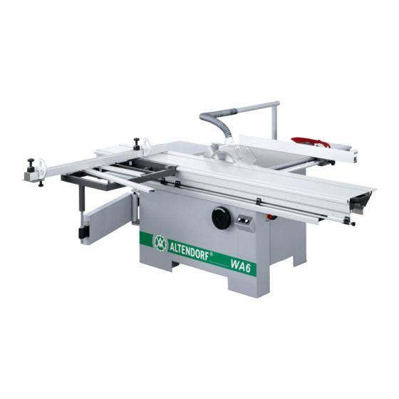
Definitions Definitions Description of machine Fig. 4-1 WA 6 Machine stand Machine table Pivot arm Main table width extension Telescopic tube Rip fence Cross-slide Handle Crosscut-mitre fence Sliding table interlock Sliding table Operating panel Table top extension Height adjustment Protective hood... -
Page 17: Terms
Definitions Terms Scoring Creation of a shallow cut in the surface of a workpiece, deep enough to pass through any coating on the workpiece, so as to prevent damage to the under- side when the main saw blade makes its cut. Scoring blade A blade that is located in front of the sawing blade, used to score the workpiece and rotate along with the feed direction. -
Page 18: Marking, Pictographs
Definitions Marking, pictographs Danger warning Hand injury warning Voltage warning Note: Read the operating manual Note: Wear ear and eye protection Definitions 0000010064-007- GB... -
Page 19: Product Description
Product description Product description Intended use Usable materials: • Laminated and unlaminated board materials (e.g. chipboard, coreboard, MDF board, ...) • Solid wood • Veneer with a suitable clamping device • Gypsum plasterboard • Cardboard • Dimensionally stable plastics (thermoset plastics, thermoplastics). Sawing these materials does not normally involve any risks with regard to dust, chips, and thermal degradation products. - Page 20 • Repair work must be carried out by our own customer service or by an ® organisation that we have authorised. Only use original Altendorf spare ® parts. Altendorf will assume no warranty for any damage that is caused by using non-original spare parts.
- Page 21 Product description Note! Any other use is deemed as unintended. ALTENDORF will not be liable for any kind of injury or damage that may result from such unintended use; the risk thereof is borne by the user alone. Unauthorised modifications by users to the machine or its electrical parts and the use of non-original parts on the machine exclude any liability by the manu- facturer for any resulting injury or damage.
-
Page 22: Dimensions And Weights
Product description • Breakage and ejection of the saw blade. • Crushing at the manually moved sliding table. • Contact with live parts when the electrical installation area is open. • Damage to hearing as a result of working for long periods of time without hearing protection •... -
Page 23: Auxiliary Power/Power Requirements
Product description Auxiliary power/power requirements Only connect the machine to a three-phase AC mains with phases L1, L2, L3 (exception 2.6 kW/1Ph). If a frequency converter or a phase converter is used in the supply line to the machine, this device or the brake module integrated in the machine may be destroyed. -
Page 24: Emissions
Product description Emissions 5.4.1 Noise - characteristic values Sound power level [dB Emission sound pressure level Tools (A)] at the workplace [dB (A)] Idling_____L = 98.3 Idling_____L = 91.0 Circular saw blade 250x3.2/ Cutting__L = 103.2 Cutting__L = 94.4 60 WZ n = 4405 rpm The noise emission values determined according to DIN EN ISO 3746 for the sound power level or DIN EN ISO 11202 and for the sound pressure level at... -
Page 25: Electromagnetic Compatibility
Product description Note! Metal dust does not usually occur when cutting aluminium. 5.4.3 Electromagnetic compatibility EMC (Electromagnetic Compatibility) is the ability of an electrical device to function in its electromagnetic environment without disruptively influencing this environment, which also includes other devices, or being disturbed by it. The machine complies with the requirements set out in the European electro- magnetic compatibility directive 2014/30/EU (EMC directive). -
Page 26: Machine Safety
Product description • Tight-fitting work clothes • Ear protection • Safety shoes Recommended: • Eye protection Note! Non-adherence to the health and safety requirements may lead to accidents and operator injuries. 5.6.2 Machine safety General: • Ensure that the workplace is uncluttered, slip-proof and well lit. •... -
Page 27: Safety Devices
Product description During use: • Never operate the machine without the protective devices intended for the specific work cycle and do not make any changes that could impair safety. • Only cut when the protective hood is properly adjusted! • When the machine is switched on, the extraction system must be activated at the same time. -
Page 28: Top Safety Hood/Riving Knife
Product description 5.6.4 Top safety hood/riving knife • Cutting without a protective device is not permitted • Ensure that the front tip of the protective hood makes contact with the workpiece during cutting • Select a suitable riving knife size for the saw blade size 5.6.5 Checking protective devices Test all protective devices with the main switch turned on and check for com-... - Page 29 Product description 2. Limit switch, plate, chip duct • Push the sliding table to its end position (centre of main saw) • The limit switch (2) is tripped when the cover plate is folded away • Actuate ON button of main and scoring saw •...
-
Page 30: Installation
Installation Installation Transport Ambient conditions Do not store the machine in an environment with explosive or corrosive gases. The ambient temperatures for transport and storage range between - 25° C and + 55° C; 70° C is permissible for a short time. The maximum air humidity must not exceed 90%, and condensation must be avoided in all cases. -
Page 31: Safety Measures Before Use/Installation
Installation Safety measures before use/installation Site of installation No special foundations are required at the installation site for the sliding table saw. The floor must have a load bearing strength suitable for the machine weight and should be flat and level. Select an installation site that provides enough clearance around the sliding ta- ble saw, allowing for the space requirements shown in the figure and the size of the workpieces to be cut. -
Page 32: Installation
Installation Setting device A setting device is located underneath the switch box (inte- rior) to ensure a stable position of the machine. • Undo the nut (1) of the setting device • Turn in the threaded pin (2) until it makes contact with the floor •... -
Page 33: Main Table Width Extension
Installation 6.3.3 Main table width extension • Align the table top width extension (1) on the table top (2) • Tighten the washer (3) with the screw (4) • Turn the nut (5) and screw (4) into the table top width extension (1) and use it to adjust the incline •... -
Page 34: Cross Slide And Crosscut-Mitre Fence
Installation 6.3.5 Cross slide and crosscut-mitre fence • Position the supporting pipe (1) of the cross slide (2) on the bolt (3) of the telescopic tube (4) • Attach the cross slide to any point of the sliding table (5) and use the eccentric lever (6) to clamp it •... -
Page 35: Electrical Connection
Installation 6.3.7 Electrical connection WARNING! Dangerous electric voltage! All work on the electrical equipment, including connection to the mains supply, may only be performed by a qualified electrician. Disconnect the machine from the mains supply before working on the electrical equipment. - Page 36 Installation Fig. 6-1 Circuit diagram Designation Designation 10Q1 Switch 10EXTS1 Emergency stop button 30S1 Sliding table limit switch 34S1 Saw blade cover limit switch 10E1 Braking device LCB 10F8 Fuse 30M1 Drive motor Installation 0000010064-007- GB...
-
Page 37: Connecting The Extraction System (Customer Side!)
Installation 6.3.8 Connecting the extraction system (customer side!) The minimum air speed at the overall connection (D = 120 mm) must be 20 m/ s. The sockets and hoses are not part of the scope of delivery! Vacuum at the overall connection D=120 mm - 1300 PA Fig. -
Page 38: Groove Tools
Installation 6.3.9 Groove tools The groove tools require a hole diameter of 30 mm and carrier holes of 10 mm Ø on a pitch circle diameter of 60 mm Ø. Loose intermediate rings may not be used. The maximum groove width is 20 mm and the maximum hub width is 15 mm. -
Page 39: Basic Machine Setting
Installation WARNING! Prior to working with the machine, check the clamping system for the groove tool for firm seating! Basic machine setting Basic machine setting is carried out at our factory during final assembly. It may be necessary to correct the machine's basic settings due to removal of various assembly groups, and transport and installation on site. -
Page 40: Swinging Arm
Installation Adjusting the main table • Undo the lock nut (1) • Adjust the table top by turning the nut (2) clockwise or counter-clockwise • Tighten the lock nut 6.4.3 Swinging arm Check the pivot arm • Lean the pivot arm against the machine stand •... -
Page 41: Cross-Slide Height
Installation 6.4.4 Cross-slide height Checking the cross-slide height • Push an approx. 0.5 mm thick test object (e.g. card- board) in between the crosscut-mitre fence and the slid- ing table • The test object must slide freely at every position Setting •... - Page 42 Installation Checking the rip fence free cut • Set the saw blade to the maximum cutting height • Position a board of approx. 300 x 450 mm (preferably MDF) on the rip fence and cut off a narrow piece • When the rising teeth pass, only a slight fluttering should be heard compared to the noise of the cutting teeth (cut- ting up)
-
Page 43: Angle Cut
Installation 6.4.6 Angle cut Before checking the angle cut, check the settings of the sliding table (see oper- ating instructions) and of the swinging arm, and correct them if necessary. The cross-slide is clamped to positions of approx. 300 mm and 1300 mm from the sliding table end. -
Page 44: 0° Setting Of The Saw Blade
Installation 6.4.7 0° setting of the saw blade Checking the 0° position of the saw blade • Set the tilt adjustment to 0°. • Set the saw blade to the maximum cutting height • Position 2 strips of approx. 100 x 400 mm upright on the crosscut-mitre fence and cut off a narrow piece •... -
Page 45: Operating
Operating Working with the sliding table saw ® The Altendorf sliding table saw is a universal machine that can be used for various saw cuts. However, the machine must be set up appropriately. To achieve safe work and a good cutting result with the sliding table saw, en- sure that •... -
Page 46: Cutting On The Crosscut-Mitre Fence/Cross Slide
Operating Sliding table interlock • Turn the star grip (1) clockwise to unlock • Pull out the star grip and position it on the locking posi- tion to lock • The locking mechanism can lock the sliding table at a middle and a retracted position. - Page 47 Operating Practical examples Cutting on the crosscut fence can be executed in two positions on the cross slide Position 1: Cutting boards • The operator presses the workpiece against the fence in the cutting direction Position 2: Cutting solid wood and boards up to 600 mm wide •...
-
Page 48: Cutting On The Manually Adjustable Rip Fence
Operating 7.1.3 Cutting on the manually adjustable rip fence Function overview • 2 stop fence settings • Infinitely variable positioning of the fence • Infinitely variable dimension setting up to a cutting width of 1000 mm Dimension setting • Release the clamping (1) •... -
Page 49: Working Examples
Operating 7.1.4 Working examples Select a suitable saw blade for each machining process and adjust the protec- tive hood according to the workpiece height. Edge cutting (trimming) • Fitting the clamping shoe on the sliding table • Deposit the workpiece with the hollow side down, and press underneath the clamping shoe. - Page 50 Operating Concealed cutting, rebating • Workpiece positioning • Push the workpiece against the rip fence with your left hand • Use the sliding table to push a workpiece forward Concealed cutting, grooving • When using a groove milling tool, replace the tool (as described in the assembly manual) •...
-
Page 51: Main Switch/Motor Protection
Operating Crosscutting short and narrow workpieces • Adjust the deflector wedge equipped with a magnet (not part of the scope of supply) so that the workpiece cuts cannot touch the rising section of the saw blade. • Only feed workpieces using the crosscut fence •... -
Page 52: Switching The Saw Drives On And Off
Operating The drive motor is protected against overload. This overload protection auto- matically switches off the motor in the event of excessive heat generation. En- sure that the scorer drive is also switched off for machines equipped with a scorer. The motor can only be switched on again when it has cooled down. It may take several minutes (max. -
Page 53: Top Safety Hood/Riving Knife
Operating Top safety hood/riving knife For a max. tool diameter of 315 mm Function overview • Chip extraction • Protective device Setting • Release the clamping lever (1) • Adjust the protective hood (2) • Tighten the clamping lever Adjustment of the main saw blade 7.5.1 Height adjustment Only set the saw blade overhang as high as necessary. -
Page 54: Tilt Adjustment
Operating 7.5.2 Tilt adjustment • Undo the clamping • Turn the hand wheel • The pivot angle is displayed at the centre of the hand wheel • Tighten the clamping WARNING! Always observe the following points prior to pivoting the saw blade: •... - Page 55 Operating • Switch off the drives. • Set the saw blade to the max. saw blade overhang and tilt to 0° • Turn off the main switch • Move the top carriage to the middle of the saw shaft, and unlock the lock at the saw blade centre by pressing the knob on the middle carriage.
-
Page 56: Saw Blade Recommendation
Operating WARNING! After the saw blade change, attach a suitable riving knife (see riving knife) and adjust the riving knife! • The distance of the riving knife from the gear rim must be set to between 3 mm and 8 mm. •... -
Page 57: Adjustment Of The Scoring Saw Blade
® cut and low stress for the operator. A selection of saw blades for Altendorf sliding table saws is summarised in this table. This table does not claim to be complete. -
Page 58: Lateral Adjustment
Operating 7.6.2 Lateral adjustment Ensure that the saw blade of the scorer are exactly in line with the main saw blade and adjusted to the corresponding width. • Position the supplied Allen key • Turn the Allen key 7.6.3 Changing the main saw blade The description of how to change the saw blade applies to both divided scoring blades and saw blades with infinitely variable cutting width adjustment. -
Page 59: Optional Modules
Operating • The scoring saw can only be started after the main saw blade has reached its operating speed (after approx. 5 sec.). To do so press the push button I labelled with the scoring saw symbol on the panels. Note! Only use the supplied tools for adjustment work! Optional modules... - Page 60 Operating Width adjustment • Release the clamping screw, approx. 2 turns. • Turn the spindle until the required dimension is reached (1 rotation = 0.5 mm) • Tighten the clamping screw • Make a test cut and, if necessary, correct the cutting width again as described above.
- Page 61 Operating Scoring blade change • Switch off the drives. • Set the scoring saw blades to the max. overhang and tilt to 0° • Turn off the main switch • Move the top carriage to the middle of the saw shaft, and unlock the lock at the saw blade centre by pressing the knob on the middle carriage.
-
Page 62: Double-Sided Mitre Fence Duplex
Operating 7.7.2 Double-sided mitre fence DUPLEX Function overview • infinitely adjustable from 0° to 90° • circular scale with 0.25° pitch • positioning at any point of the sliding table • option of crosscutting workpieces of up to 1350 mm in length (when the extended stop fence is used, up to 2150 mm in length) •... -
Page 63: Large Protective Hood
Operating 7.7.3 Large protective hood The same safety requirements as for the "protective hoods fastened on the riv- ing knife" apply, in addition to: Prior to setting the saw blade to an incline, attach a suitable protective hood. Changing the protective hood •... -
Page 64: Cleaning / Maintenance
Cleaning / maintenance Cleaning / maintenance Safety measures WARNING! Please observe: • Always turn off the main switch and secure it against being turned on again before doing any maintenance work! Non-observance can lead to severe injuries! Note! Before using solvents and cleaning agents, make sure that these substances do not cause damage to the painted, anodised or galvanised surfaces as well as plastic parts. - Page 65 Cleaning / maintenance Interval Components to be cleaned Remove/clean with • Vacuum or brush Daily Machine table Top and bottom carriage • Wipe off Weekly Top carriage • Sub-rollers • Guide rods (internal) Bottom carriage • Guide rods • Bottom guide Round rod (rip fence) •...
- Page 66 Cleaning / maintenance Note! Remove the oil from all lubricated points using a cloth! Sliding table Fig. 8-1 Remove dirt and resin residue from the guide of the sliding table using a cloth soaked in spirit Fig. 8-2 Remove dirt from the bottom of the guide of the sliding table Fig.
-
Page 67: Repair/Maintenance By The User
Cleaning / maintenance Round rod (rip fence) Fig. 8-4 Spray round bar. Subsequently move the block up and down. Repair/maintenance by the user • The bearings of the main saw shaft and scoring saw shaft are encapsu- lated and lubricated for life, making relubrication unnecessary. •... -
Page 68: Faults/Problems/Troubleshooting
Faults/problems/troubleshooting Faults/problems/troubleshooting WARNING! As a rule, troubleshooting involves a higher risk. For this reason, pay particular attention to safety aspects when carrying out the necessary measures. • Turn off the main switch and secure it against being turned on again Fault Cause Troubleshooting... - Page 69 Faults/problems/troubleshooting Fault Cause Troubleshooting Control circuit fuses Turn off the main switch, open the switch cabinet and defective identify which of the fuses F1, F2, F8 is defective. Find and eliminate the cause. Replace defective fuses, only using fuses of the same rating! Workpiece Blunt saw blade Fit a sharp saw blade.
- Page 70 Faults/problems/troubleshooting Fault Cause Troubleshooting Workpiece jammed. Insert a riving knife in the cutting line or use a wider riving knife. Operating error Guide the workpiece either at the LH or the RH fence. Do not guide the workpiece on the rip fence when cutting with the sliding table.
-
Page 71: Technical Data
Technical data Technical data 10.1 Standard equipment Main saw Tool holder diameter 30 mm Saw blade tilting range 0 - 46° Idling speed 4200 rpm Sliding table Sliding table cutting length See table Crosscut-mitre Cutting to length on the crosscut-mitre 2600 mm fence fence... - Page 72 Technical data Sliding table cutting lengths Maximum cutting length for placing board material against the crosscut-mitre fence. These cutting lengths refer to mechanical travel paths, i.e. from end stop to end stop on the sliding table. Sliding table length [mm] 1600 2000 2600...
-
Page 73: Maintenance And Repairs
Altendorf GmbH will not accept any liability or guarantee for damage resulting from the use of non-original spare parts and accessories. -
Page 74: Customer Service Addresses
Maintenance and repairs 11.2 Customer service addresses Altendorf GmbH Service department Wettinerallee 43/45 D-32429 Minden Post office box D-32377 Phone: +49 571 9550222 Telefax: +49 571 9550111 e-Mail: service@altendorf.de www.altendorf.com Maintenance and repairs 0000010064-007- GB... - Page 75 Maintenance and repairs Maintenance and repairs 0000010064-007- GB...
- Page 76 Maintenance and repairs Maintenance and repairs 0000010064-007- GB...
Need help?
Do you have a question about the WA 6 and is the answer not in the manual?
Questions and answers