
Related Manuals for Altendorf WA 80


Summary of Contents for Altendorf WA 80
- Page 1 ® Operating manual WA 80 Version 05/2021 0000010046_012 Translation of the original operating instructions...
- Page 2 Altendorf, WA 80, Magis, RAPIDO, are registered trademarks of Altendorf GmbH in various countries. 0000010046-012- GB...
-
Page 3: Table Of Contents
Table of contents Table of contents Foreword Identification Machine identification ..................Certificates..................... Marks of conformity ..................Product description Marking, pictographs ..................Intended use....................Dimensions and weights................Auxiliary power/power requirements ............. Emissions ...................... 3.5.1 Noise - characteristic values................3.5.2 Electromagnetic compatibility ................ 3.5.3 Dust ....................... - Page 4 Table of contents 5.3.1 Telescopic tube for swinging arm ..............5.3.2 Main table length extension................5.3.3 Rip fence ....................... 5.3.4 Cross-slide and crosscut fence ..............5.3.5 Sliding table ....................5.3.6 Electrical connection..................5.3.7 Connecting the extraction system (customer side!)........5.3.8 Basic machine setting..................
- Page 5 Table of contents Technical data Standard equipment ..................127 Special equipment ..................129 Maintenance and repairs General......................131 Customer service addresses................. 132 Table of contents 0000010046-012- GB...
- Page 6 Foreword Foreword Prior to commissioning/start-up, thoroughly read this operating manual. No liability will be accepted for any injury, damage or malfunctions/shut- down times resulting from non-observance of this operating manual! Persons operating this sliding table saw must been sufficiently qualified and instructed! This operating manual cannot be regarded as a binding type description as the manufacturer may have carried out technical modifications.
-
Page 7: Identification
Identification Identification Machine identification The type label attached to the machine stand is used to determine the machine identity and further important key data. Meaning of the specified designations: Fig. 2-1 Type label Typ: Machine designa- tion Nummer: Machine-specific identification number Baujahr: Year when... -
Page 8: Certificates
Michael Domurath, Head of the mechanical design department compile the Altendorf GmbH technical documentation: ® Product: Sliding table saw, type WA 80 Machine number: Authority named for prototype testing DGUV Test Prüf-und Zertifizierungsstelle Holz according to annex IX: Fachbereich Holz und Metall Vollmoellerstraße 11... - Page 9 Identification EC prototype testing certificate Identification 0000010046-012- GB...
- Page 10 Identification Identification 0000010046-012- GB...
- Page 11 Identification GS test certificate Identification 0000010046-012- GB...
- Page 12 Identification Identification 0000010046-012- GB...
- Page 13 Identification DGUV Test Certificate Identification 0000010046-012- GB...
- Page 14 Identification Identification 0000010046-012- GB...
- Page 15 Identification Certificate renewal Identification 0000010046-012- GB...
- Page 16 Identification C US certificate Identification 0000010046-012- GB...
- Page 17 Identification Identification 0000010046-012- GB...
-
Page 18: Marks Of Conformity
Identification Marks of conformity CE symbol GS symbol “Wood dust approved” sym- C US mark Identification 0000010046-012- GB... -
Page 19: Product Description
Product description Product description Marking, pictographs Danger warning Hand injury warning Laser beam warning Crushing risk warning Voltage warning Note: Wear ear pro- tection Intended use The sliding table saw and the workpiece guide equipment supplied with it are intended to be used for cutting wood and similar materials such as: •... - Page 20 Product description • Sheet steel • Sheet brass • Sheet copper • Round wood without the use of a suitable clamping device Tools: • The chosen saw blade must be suitable both for the specific work cycle (e.g. longitudinal cutting or crosscutting) and for the specific material. •...
- Page 21 • Repair work must be carried out by our own customer service or by an ® organisation that we have authorised. Only use original Altendorf spare ® parts. Altendorf will assume no warranty for any damage that is caused by using non-original spare parts.
- Page 22 Non-adherence may lead to knee injuries! Note! ® Any other use is deemed as unintended. Altendorf will not be liable for any kind of injury or damage that may result from such unintended use; the risk thereof is borne by the user alone.
- Page 23 Product description Foreseeable misuse: • Working with the safety hood swung up • Working with the safety hood swung away • Failure to use the push stick or push block for cuts < 120 mm • Moving the sliding table without using the handle •...
- Page 24 Product description Residual risk: Even when the machine is operated in accordance with its intended use and all pertinent safety regulations, the following residual risks may be encountered because of design changes caused by the intended use in question: • Contact with the main saw blade and the scoring blade in the cutting area when the protection hood is not correctly adjusted.
-
Page 25: Dimensions And Weights
Product description Dimensions and weights [mm] [kg] [kg] [kg] [kg] [kg] [kg] [mm] [mm] 2250 855-1282 970-1495 131-142 203-230 2060x960x500 2580x660x330 2600 855-1282 970-1495 131-142 203-230 2060x960x500 2930x660x330 3000 855-1282 970-1495 131-142 203-230 2060x960x500 3330x660x330 3200 855-1282 970-1495 131-142 203-230 2060x960x500 3530x660x330 3400... -
Page 26: Auxiliary Power/Power Requirements
RCMAs with an isolator (preferably) or by type-B RCDs (universal-current-sen- sitive residual-current circuit breakers). The following devices can be used: Manufacturer: Doepke switching devices; these switching devices can also be purchased via Altendorf. • DFS4 040-4/0,30-B NK, release current 300 mA •... - Page 27 Product description Auxiliary power/power requirements Motor Voltage Frequency Nominal current Fusing Without/with scoring [kW] [Hz] blade 380 - 420 7,5 / 9,5 380 - 420 11,5 / 13,5 380 - 420 15,5 / 17,5 7,5 / 8,5 19/22,5 9,8/11,5 Product description 0000010046-012- GB...
-
Page 28: Emissions
Product description Emissions 3.5.1 Noise - characteristic values Sound power level Emission sound pressure level Tool [dB (A)] at the workplace [dB (A)] Idling_____L = 98,1 Idling_____L =88,5 Circ. saw blade 350x3,5/54 WZ Running__L = 102,5 Running__L = 85,2 n = 4160 rpm The noise emission values determined according to DIN EN ISO 3746 for the sound power level or DIN EN ISO 11202 for the sound pressure level at the workplace on the basis of the working conditions stated in ISO 7960 Appendix... -
Page 29: Dust
Product description 3.5.3 Dust The dust emission values – measured in accordance with the “Principles for Testing Dust Emission (Concentration Parameters) from Woodworking Ma- chines” issued by the German trade association's technical committee for wood – are below 2 mg/m When the machine is attached to a correctly functioning extraction system with an air speed of at least 20 m/s (measured after joining the two extraction con- nections) you can assume it is and will stay compliant with the technical refer-... - Page 30 Product description • the sliding table • the sliding table guides • the pivoting segments • the round rod of the rip fence • the machine interior • the machine surroundings Remove any chips and dust adhering to the machine with a vacuum cleaner. To remove resin residue, it is advisable to use a cleaning agent which dissolves resin.
- Page 31 Product description Lubrication • The bearings of the main saw shaft and scoring saw shaft are encapsu- lated and lubricated for life, making relubrication unnecessary. • Regularly clean and lubricate the pivoting segments. The intervals (2 weeks) depend on the duration of use. •...
- Page 32 Product description Lubrication, electromotive rip fence (model X) Fig. 3-3 Lubricating point, linear guide Fig. 3-4 Lubricating point, spindle drive To lubricate the spindle, the rip fence must be moved to its max. cutting posi- tion, so that the lubricating nipples can be reached from the bottom with the supplied grease gun.
-
Page 33: Safety Information
Product description CAUTION! Do not use lubricants containing graphite or MoS2 additives! Safety information 3.6.1 Operational safety The operation of woodworking machines with a manual feed involves a high risk in the event of incorrect handling. Therefore always observe the safety in- formation that is summarised in this chapter as well as government and other industrial safety regulations (e.g. - Page 34 Such riving knifes can be obtained from machinery suppliers or ® directly from Altendorf • Use an anti-kick device for insert cuts, e.g. the front of the clamping shoe.
- Page 35 Product description • Prior to cutting aluminium, thoroughly clean the machine and remove all remaining chips and dust to prevent ignition of remaining chips/dust. • The sawdust generated during cutting not only impairs visibility but is also partially hazardous to health. Therefore, the machine must be connected to a chip extraction system with both extraction sockets.
-
Page 36: Safety Devices
Product description 3.6.2 Safety devices ® Altendorf sliding table saws have been developed in compliance with Europe- an standard DIN EN ISO19085-5: 2018-02 “Woodworking machines - Safety - Part 5: Dimension saws“ (ISO 19085-5:2017). During the design stages great importance was attached to creating optimum working conditions, ranging from numerous mechanical and electrical safety devices to noise insulation and reduction of dust emission. -
Page 37: Top Safety Hood/Riving Knife
Product description 3.6.3 Top safety hood/riving knife For a max. tool diameter of 450 mm: • Top safety hood fitted separately from the riving knife for max. saw blade diameter of 450 mm, available in a narrow and a wide format made of poly- carbonate to optimally cover the section of the blade not required for saw- ing above the machine table with a safeguard against lifting beyond the maximum cutting height of +5 mm. -
Page 38: Checking Protective Devices
Product description 3.6.4 Checking protective devices Test all protective devices with the main switch turned on and check for com- pleteness and noticeable damage. For the tests, install the largest possible saw blade and set the maximum per- missible speed. 1. -
Page 39: Handling Batteries / Accumulators
Product description WARNING! The safety-relevant protective devices/guards exist for the operator’s protec- tion. If safety-relevant components are damaged, immediately stop and secure the machine and initiate the required repair work. The operator must assess damage to non-safety-relevant components and initiate repair work accord- ingly. - Page 40 The risk potential of lithium batteries is, in addition to the product design, pri- marily determined by the module or system capacity. ® The types used by Altendorf are low-capacity lithium batteries (batteries > 1 kg). The information for damage prevention applies to both new and used bat- teries.
-
Page 41: Definitions
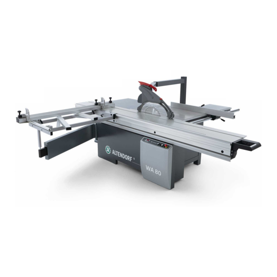
Definitions Definitions Description of machine Fig. 4-1 WA 80 X Machine frame Protection hood Swinging arm Push stick Telescopic tube Main table width extension Cross-slide Motor driven rip fence Crosscut-mitre fence Operating unit at eye level Sliding table Return handle... -
Page 42: Terms
Definitions Sliding table Return handle Main table length extension Sliding table interlock Terms Scoring Creation of a shallow cut in the surface of a workpiece, deep enough to pass through any coating on the workpiece, so as to prevent damage to the under- side when the main saw blade makes its cut. -
Page 43: Installation
Installation Installation Transport and storage Ambient conditions Do not store the machine in an environment with explosive or corrosive gases. The ambient temperatures for transport and storage range between - 25° C and + 55° C; 70° C is permissible for a short time. The maximum air humidity must not exceed 90%, and condensation must be avoided in all cases. - Page 44 Installation Fig. 5-1 Foundation plan DANGER! Danger of crushing! • For operation with the max. workpiece weight, secure the machine against tilting! • Ensure that there is sufficient safety clearance from building parts and other machines! Fig. 5-2 Space requirement Installation 0000010046-012- GB...
- Page 45 Crosscut fence up to 2500 mm: 1445 mm - max. 2630 mm Crosscut fence up to 3200 mm: 1800 mm - max. 3350 mm Crosscut-mitre fence up to 3500 mm: 1970 mm - max. 3680 mm ( WA 80 X) Dimension D: Cutting width + 310 mm with man. RF adjustment...
-
Page 46: Installation
Installation Installation 5.3.1 Telescopic tube for swinging arm Fig. 5-3 Installing the telescopic tube [1] Undo the cheese head screw. [2] Push in the telescopic tube from the front through the housing for the swinging arm. [3] Insert and tighten the cheese head screw. Installation 0000010046-012- GB... -
Page 47: Main Table Length Extension
Installation 5.3.2 Main table length extension Fig. 5-4 Installation main table length extension (Type TE/ NT/ T) [1] Guide the pins of the table length extension into the holes on the face of the table plate. [2] Secure loosely to the table plate with two M10 nuts and shake proof washers (1). [3] If necessary, correct the alignment and flushness by readjusting the support screws (2). -
Page 48: Rip Fence
Installation 5.3.3 Rip fence Fig. 5-6 Installation main table width extension (Type TE / NT/ T) [1] Guide the pins of the table length extension into the holes on the face of the table plate. [2] Secure loosely to the table plate with two M10 nuts and shake proof washers(1). [3] If necessary, correct the alignment and flushness by readjusting the support screws (2). - Page 49 Installation Fig. 5-8 Installing the measuring bar [1] Fit the measuring bar easily with M6x30 countersunk screws (1) [2] Knock a 6x45 clamping pin (2) through [3] Tighten the countersunk screws(1) Fig. 5-9 Installing the rip fence [1] Put the fence bar bolts (1) through the holes in the main table. [2] Attach the M20 nuts from the rear of the main table and tighten them.
- Page 50 Installation Motorised rip fence (Type X) Fig. 5-10 Installing the motorised rip fence [1] Fit the axis in front of the machine table with 3 M10 bolts. [2] Fasten on the ohter side with washers and M10 nuts. Make sure the axis is flush with the machine table.
-
Page 51: Cross-Slide And Crosscut Fence
Installation 5.3.4 Cross-slide and crosscut fence Installing the cross-slide The cross-slide must be attached to every point of the outer-lying round bar of the sliding table, and must be clamped. Assembly steps: - Place the supporting pipe of the cross-slide [1] onto the bolt [8] of the tele- scopic tube - Tilt the cross-slide to the sliding table, suspend and clamp using the eccentric lever [2];... - Page 52 Installation Cross-slide clamping WA/WGA crosscut fence Fig. 5-14 Clamping lever [1] Clamping lever [2] Safety locking mechanism [3] Stop, safety locking mechanism for displacing the cross-slide [4] Drill hole, safety locking mechanism for removing the cross-slide To push the cross-slide to other positions on the sliding table, undo the clamp- ing lever [1] up to the stop of the safety locking mechanism.
- Page 53 Installation Crosscut fence, 90° only Fig. 5-15 Installing the 90° crosscut fence 1. Place the crosscut fence on the cross-slide such that the clamping bolts [1] can be inserted in the grooves [2] 2. Tighten the clamping bolts [1], positioning is carried out by means of the tapered surfaces Changing the 90°...
- Page 54 Installation Crosscut-mitre fence Fig. 5-16 Crosscut-mitre fence operating elements [1] Clamping lever 90° position [2] Clamping degree scale [3] Clamping pivot point [4] Clamping lever, cross-slide / sliding table [5] Clamping, C profile Installing the standard crosscut-mitre fence / with DIGIT L + LD: •...
- Page 55 Installation Fig. 5-17 Installing the WGA [1] Clamping degree scale [2] Clamping pivot point [3] Ball bearing Installation 0000010046-012- GB...
- Page 56 Installation 90° clamping Fig. 5-18 90° clamping [1] Support roller [2] Clamping lever [3] 90° stop [4] Pressure piece on the clamping lever [5] Guide bolt(s) Fig. 5-19 Crosscut-mitre fence left-hand side [1] Clamping screw, telescopic extension [2] Guide groove for 90° position [3] Clamping piece, 90°...
- Page 57 Installation Crosscut-mitre fence WGA_LD Crosscut-mitre fence with digital angle and length measurement Fig. 5-20 WGA_LD [1] Clamping lever 90° position [2] Indexing bolt, angle measurement [3] Clamping pivot point [4] Clamping lever [5] Clamping, angle measurement [6] Clamping, C profile Assembly of the crosscut fence •...
- Page 58 Installation • Lower the crosscut-mitre fence so that the bolt enters the guide carriage hole • Turn in clamping screw [5] loosely • Push the T-nut with clamping screw [3] into the pivot • Swivel the WGA to its 90° position and clamp with clamping lever [1]. •...
- Page 59 Installation Fig. 5-22 90° clamping [1] Support roller [2] Clamping lever [3] 90° stop [4] Pressure piece on the clamping lever [5] Guide bolt(s) Fig. 5-23 WGA_LD, LH side [1] Clamping screw, telescopic extension [2] Guide groove, 90° position [3] Clamping piece, 90° position Installation 0000010046-012- GB...
-
Page 60: Sliding Table
Installation 5.3.5 Sliding table Fig. 5-24 Bottom carriage stop [1] Place the bottom carriage on the machine frame and push against the stop screws. [2] Screw on the bottom carriage. Fig. 5-25 Installing the middle carriage [1] Place the middle carriage on the bottom carriage so that the interlock is pointing to the right. - Page 61 Installation Fig. 5-27 Back stop [1] Fit the back stop. Fig. 5-28 Top carriage stop [1] Check whether the stop on the top carriage and the stop on the bottom carriage hit the end position at the same time. [2] Adjust if necessary. Fig.
-
Page 62: Electrical Connection
Installation 5.3.6 Electrical connection WARNING! Dangerous electric voltage! All work on the electrical equipment, including connection to the mains supply, may only be performed by a qualified electrician. Disconnect the machine from the mains supply before working on the electrical equipment. -
Page 63: Connecting The Extraction System (Customer Side!)
Installation If the machine is connected via a flexible supply line, a rubber-sheathed cable (wire marking H07RN-F) must be used. Required plug-in device: Round con- nector in accordance with DIN 49463. Fig. 5-30 Model X/TE Designation Designation Main switch F1-F2 Control fuse (primary) F7-F9 Control fuse (secondary) - Page 64 Ensure that the extraction system is suitable for extracting aluminium chips! • Always collect wood, aluminium and plastic chips separately! • Prior to cutting aluminium, thoroughly clean the machine and remove all remaining dust and chips! Fig. 5-31 Extraction connection WA 80 X/ TE Installation 0000010046-012- GB...
- Page 65 Installation Fig. 5-32 Extraction connection, chip duct Installation 0000010046-012- GB...
-
Page 66: Basic Machine Setting
Installation 5.3.8 Basic machine setting Basic machine setting is carried out at our factory during final assembly. It may be necessary to correct the machine's basic settings due to removal of various assembly groups, and transport and installation on site. The machine elements to be checked are described below. - Page 67 Installation Main table Checking the main table • Position the rip fence straight edge on the sliding table • Move the centre carriage back and forth • Ensure that the top carriage is approx 0.1 mm above the level of the table top Adjusting the main table •...
- Page 68 Installation Fig. 5-35 Crosscut fence setting Installation 0000010046-012- GB...
- Page 69 Installation Cross-slide height Check Fig. 5-36 Checking the cross-slide height Push a piece of cardboard of approx. 0.5 mm thickness between the crosscut fence and the sliding table; it must be possible to move the cardboard freely in every position. The crosscut fence must be parallel to the surface of the sliding table! Setting Fig.
- Page 70 Installation Setting free cut Sliding table Definition: The sliding table, the saw blade and the rip fence are not parallel to each other, so the crosscut fence and the rip fence do not form a 90° angle. The sliding ta- ble runs to the left out of the direction, by a fraction of a millimetre.
- Page 71 Installation Setting: Manually adjustable rip fence Fig. 5-38 Setting free cuts, standard rip fence • Undo the nuts on the bolts connecting the round bar and the table width extension • The degree of free cut on the rip fence can be altered by adjusting the mid- dle lock nuts •...
- Page 72 Installation Angle cut Checking the angle cut Before checking the angle cut, check the settings of the sliding table and of the swinging arm, and correct them if necessary. Carry out the check as follows: Fig. 5-40 Angle cut As the tool, use a sharp saw blade, D = 350 mm/ 3.5/2.5/72 teeth alternate bev- el at n = 5000 rpm.
- Page 73 Installation 0° setting of the saw blade Check: • Set the tilt adjustment to 0°. • Position 2 strips (approx. 100 mm wide) vertically in front of the crosscut fence, cut in this position and butt the cut surfaces against each other. •...
-
Page 74: Operating
Operating Operating Working safely with the dimension saw 6.1.1 Cross-slide/crosscut fence Fig. 6-1 Cutting boards The crosscut fence can be installed at two positions on the cross-slide. Position 1: Cutting boards The operator presses the workpiece against the fence in the cutting direction. Fig. - Page 75 Operating Function description of the crosscut-mitre fence • The crosscut-mitre fence can be swung by 49° (angle indicated on scale), plus angle-dependent adjustable length compensation via a scale. • Ball bearings run in the sliding table groove, preventing the stop fence coming into the cutting plane when swung •...
- Page 76 Operating Length compensation Fig. 6-4 Length compensation scale By shifting the crosscut-mitre fence, the length dimension can be adjusted for the set angle. Changing the crosscut-mitre fence • Release the clamping screw and clamping lever • Push the crosscut-mitre fence to the 2nd position •...
-
Page 77: Rip Fence
Operating 6.1.2 Rip fence Fig. 6-5 Position of the clamping screw For cutting parallel, the rip fence is pushed up to the required dimension. The set dimension is read off from the edge of the aluminium profile. The dimension scale can be adjusted to the individual tool thickness after re- leasing the knurled screw. - Page 78 Operating The stop fence of the rip fence can be adjusted in the cutting direction and to the profile height. Clamp it in the required position with the top eccentric lever. For crosscutting short workpieces and for recessing or other work cycles during which offcuts can become jammed between the stop and the saw blade, the stop fence is moved forward until its rear end is in front of the saw blade.
-
Page 79: Double Roller Carriage
Operating 6.1.3 Double roller carriage Sliding table operating elements: Fig. 6-8 Sliding table operating elements Hand grip with optional saw controls and infinitely variable carriage locking Operating 0000010046-012- GB... -
Page 80: Working Examples
Operating Working examples General information The Altendorf sliding table saw is a universal machine that can be used for var- ious saw cuts. However, the machine must be set up appropriately. Tools First, make sure that you only use saws in perfect condition, that the riving knife is correctly set and that the top protection hood is lowered close above the workpiece to be cut. - Page 81 Operating Edge cutting (trimming) Fig. 6-9 Edge cutting Tool: Circular saw blade for longitudinal cuts Work cycle: Fit the clamping shoe on the sliding table. Lay the workpiece with the hollow side down, and press underneath the clamping shoe. Push the workpiece forward by applying pressure with the ball of your right hand on the workpiece edge.
- Page 82 Operating Longitudinal cutting of narrow workpieces Fig. 6-10 Longitudinal cutting Workpiece width < 120 mm Tool: Circular saw blade for longitudinal cuts Work cycle: Set the rip fence to the required cutting width. Lower the top pro- tection hood according to the workpiece height. Push the workpiece (aligned along the fence) and sliding table forward, using the push stick in the vicinity of the saw blade, and push the parted workpiece beyond the riving knife.
- Page 83 Operating Work cycle: Set the aluminium straight edge of the rip fence to the low guide surface. Lay the workpiece on the sliding table and press against the rip fence with your left hand. Push the workpiece forward with the sliding table; use the push stick in the vicinity of the saw blade to push the strip beyond the riving knife.
- Page 84 Operating Concealed cutting, rebating Fig. 6-13 Concealed cutting Tool: Circular saw blade for fine cuts Work cycle: When rebating, select the cutting sequence so that the cut-out strip is produced on the side of the blade opposite the fence. Lower the protection hood onto the workpiece and ensure good workpiece guidance (left hand presses the workpiece against the rip fence).
- Page 85 Operating Work cycle: Close the table opening with a table strip matched to the grooving tool. Set the tool to the required groove depth. Leave the riving knife in as a rear tool cover. When pushing forward, firmly press the workpiece onto the ta- ble (otherwise danger of unintentional insert operation.).
- Page 86 Operating Crosscutting short and narrow workpieces Fig. 6-16 Crosscutting Tool: Circular saw blade for fine cuts Work cycle: Adjust the deflector wedge featuring a magnet (not part of the scope of supply) such that the workpiece cuts cannot touch the rising section of the saw blade.
- Page 87 Operating Dividing large boards Fig. 6-17 Dividing For this work cycle, the dimension can be set both on the rip fence and on the crosscut fence. If several pieces of the same size are to be cut from a large board, it is best to first cut off parallel strips at the rip fence and then cut them to the required dimension.
-
Page 88: Machine Operation
Operating Machine operation 6.3.1 Main switch/Motor protection Main switch Before the saw drives are switched on the main switch must be set to position I. The main switch is BLACK which means that this main switch has no EMER- GENCY OFF function! When the main switch is used to turn the machine off the saw drives stop with no braking! Motor protection If the motor protection cuts in it is a sign that the motor is being overloaded and... -
Page 89: Switching The Drives On And Off
Operating 6.3.2 Switching the drives on and off Before switching on the machine, make sure that all protective devices required for the respective work cycle are attached and operative. In addition, check that the saw blades are correctly fitted and that there are no workpieces or other ob- jects in their vicinity. -
Page 90: Setting The Speed
Operating 6.3.3 Setting the speed The following speeds can be set on the main drive by changing over the belt : 3000, 4000, 5000 revolutions/minute. Fig. 6-20 Changing the speed [1] Lever [2] Speed control Speed change • Switch off drive. •... -
Page 91: Changing The Main Saw Blade
• Do not fit any saw blades that are cracked or damaged in any way. • Only fit saw blades with a diameter between 250 and 450 mm (WA 80 X/ TE). • Check that the set rotational speed is suitable for the saw blade. For assembled saw blades, the maximum admissible rotational speed is speci- fied on the blade as n max =.. - Page 92 Operating • Before fitting the new saw blade, remove any adhering chips and dust from both flanges. • Place the saw blade and front flange onto the saw shaft, turn in by hand and tighten with the wrench. • Check the riving knife for strength and distance from the saw blade. •...
-
Page 93: Saw Blade Recommendation
Operating 6.3.5 Saw blade recommendation Workpiece Softwood lengthwise 60 - 80 24 W 28 W 32 W 36 W 40 W 48 W 54 W Softwood crosswise 60 - 80 40 W 48 W 54 W 60 W 48 W 60 W 72 W Hardwood lengthwise... - Page 94 A selection of saw blades for the Altendorf sliding table saw is shown in the table (p.29). This table makes no claims to be complete. Since the figures for the...
- Page 95 Operating 6.3.6 Table locking Fig. 6-22 Locking The sliding table can be locked in any position using the lever at the operator end. The workpiece can thus be laid up against the crosscut fence without the easy running slding table being involuntarily set in motion. The table is un- locked by turning the lever at the end of the upper carriage by hand.
-
Page 96: Rip Fence Fine Adjustment
Operating 6.3.7 Rip fence fine adjustment Fig. 6-23 Rip fence with fine adjustment Manual fine adjustment enables the rip fence to be adjusted precisely. The fence can be set with pinpoint precision by means of the adjusting screw. Machine control system 6.4.1 Adjustment of the main saw blade Fig. - Page 97 Operating DANGER! Danger from kicked-out offcuts! Danger from the blade touching the rip fence! • Clear the main table of any workpieces in the tilting area • When cutting widths less than 180 mm, set the rip fence straight edge in the flat position Adjusting the tilt angle: •...
- Page 98 Operating Calibrating the tilt angel display • Tilt the saw blade into the vertical position and check the 90° angle. • Press the RESET key for 3 seconds, the displays shows 0.0. • The machine is calibrated. Fig. 6-25 Calibrating (Type X / TE) Operating 0000010046-012- GB...
-
Page 99: Protection Hood
Operating Protection hood Fig. 6-26 Normal working position Swing away the protection hood as follows: • Turn off the main switch and secure against turning on again • Actuate the release lever Fig. 6-27 Clamping screw Operating 0000010046-012- GB... - Page 100 Operating • Swing the protection hood away Fig. 6-28 Protection hood swung away Note! After completing the work cycle, immediately swing the protection hood back into the normal working position and lock it with the clamping screw . WARNING! You may only work with a removed protection hood in special cases and with increased caution, e.g.
-
Page 101: Optional Modules
Operating Optional modules Note! A separate operating manual is attached for the following options: • DUPLEX • Parallelogram cross slide [PQS] • Spray unit ® • Tip-Servo-Drive • Vacuum clamping in the sliding table 6.6.1 Rip fence with DIGIT X DIGIT X Display DIGIT X The electronic measuring system with digital display and fine setting system... - Page 102 Operating Undo the clamping screw. Remove the housing accommodat- ing the display electronics. Undo the screws and remove the Change the batteries, ensuring cor- cover. rect polarity. Basic setting of the display unit The basic setting of the display unit is needed in order to adapt the measuring system to the machine situation.
- Page 103 Operating Calibrating the display unit Calibration of the display unit is required when the fence has been moved un- der the main table. • Push the rip fence to the left against the mechanical stop. • Hold the F button down and briefly press the RESET button; the display shows the basic setting again.
-
Page 104: Scoring Saw
Operating 6.6.2 Scoring saw The scorer cuts approx. 1-2 mm into the material from below; then the main saw blade cuts through it. Make sure that the scoring blade is exactly in line with the main blade and is set to the corresponding width. •... - Page 105 Operating • Once the desired operating height has been reached, re-tighten the clamp- ing screw (1). Downward: • To reduce the operating height, undo the clamping screw (1) and turn the setting screw (2) RIGHT. • Then close the hood so that the scoring unit can return to its resting posi- tion.
- Page 106 Operating Changing the saw blade The description of how to change the saw blade applies to both divided scoring blades and saw blades with infinitely variable cutting width adjustment. Only use saw blades with a diameter of 120 mm and a hole diameter of 22 mm! •...
- Page 107 Operating Adjusting the saw blade width Standard saw blade • Use the spacer disks to set the scoring blade to a width 0.1 mm larger than the width of the main saw blade. • First align the scorer with the main saw on the table side. •...
- Page 108 Operating Replacing the scoring blade for RAPIDO Fig. 6-33 RAPIDO saw blades Remove the adjustment unit from the machine. It may be necessary to loosen the clamping screw because an excessively tight clamping screw can cause the ad- justment unit to jam on the shaft! Removal: Using the Allen wrench: •Release the clamping screw (1), turn the spindle (2)
-
Page 109: Motor Driven Rip Fence
Operating 6.6.3 Motor driven rip fence Motorised rip fence (Type X) The motorised rip fence has a traverse speed of 200 mm/sec. and an accuracy of ± 0,1 mm. The fence automatically recognizes the position it’s in, especially when it reaches the danger area around the saw blade. it has an emergency cut-out to prevent the risk of crushing. -
Page 110: Dimension Display Unit Digit L
Operating 6.6.4 Dimension display unit DIGIT L Fig. 6-35 DIGIT L The dimensions that have been set are displayed digitally in the 150 mm to 3200 mm range to an accuracy of ± 0.1 mm. The proximity sensor operates wear-free and is not sensitive to dust. A precise adjustment system is used for precision setting in 1/10 mm increments. - Page 111 Operating Power supply Power is supplied by a rechargeable battery. The charging state is shown in the bottom right hand corner of the display. The batteries can be recharged using the supplied charger. Changing the rechargeable battery Fig. 6-37 Changing the rechargeable battery for DIGIT L , DIGIT LD Fig.
- Page 112 Operating Basic setting / calibration of the display unit The basic setting of the display unit is required in order to adapt the measuring system to the machine situation. Check and, if necessary, re-enter the basic settings following each tool change. How to proceed: •...
-
Page 113: Palin
Operating 6.6.5 PALIN PALIN Fig. 6-40 PALIN Function overview • 2 fence settings • Infinitely variable positioning of the fence • Additional support surface Dimension setting • Release the clamping lever (1) • Set PALIN to the required dimension • Tighten the clamping lever (1) Fence setting •... - Page 114 Operating Additional support surface • Move the clamping lever (1) to a horizontal position • Fold down the device PALIN_D with digital dimension display and precision setting system Fig. 6-41 PALIN D The PALIN D has the same features as the PALIN, but with a digital value dis- play and a precision setting system down to an accuracy of 1/10 mm.
- Page 115 Operating • Hold the F button down; the right-hand digit of the display starts flashing after approx. 3 s • Keep the F button pressed • Pressing the + button increases the flashing digit by 1 each time. After the maximum numeric value 9, the numbers start again at 0.
-
Page 116: Steg (Second Support)
Operating 6.6.6 STEG (second support) Fig. 6-42 STEG The STEG provides additional support when cutting large panels and can be positioned anywhere along the sliding table using ist cam clamping handle. 6.6.7 Workpiece hold-down device Electro-pneumatic hold-down device Fig. 6-43 Electro-pneumatic hold-down device Operating 0000010046-012- GB... - Page 117 Operating The electro-pneumatic hold-down device secures the workpiece to the crosscut fence and operates with a clamping force of max. 1000 N at a pressure of 6 bar. The maximum clamping height is 90 mm. The safety cylinder only clamps the workpiece when the pressure plate is posi- tioned vertically in relation to the cylinder axis.
- Page 118 Operating Fig. 6-44 Remote control, hold-down device The up/down movement is controlled wirelessly by a hand-held radio transmit- ter using the respective button. If two hold-down units are used, both are controlled simultaneously. When the button is pressed, the lamp lights up in red. If no red signal appears, the battery CR2032 must be replaced.
-
Page 119: Mitre Fences
Operating 6.6.8 Mitre fences Single-sided mitre fence Fig. 6-45 Single-sided mitre fence The fence can be fitted quickly and easily to the sliding table with an eccentric clamping system. Dimension scales are inclined in order to stay in the opera- tor's field of vision. -
Page 120: Faults
Faults Faults WARNING! As a rule, troubleshooting involves a higher risk. For this reason, pay particular attention to safety aspects when carrying out the necessary measures. • Turn off the main switch • Secure the main switch against unintentional switching on. Fault Cause Troubleshooting... - Page 121 Faults Fault Cause Troubleshooting Overload protec- Change saw blade or reduce feed speed. tion has responded Wait until the motor has cooled down due to blunt saw blade or excessive feed speed. Control circuit Turn off the main switch, open the switch fuses defective cabinet and identify which of the fuses F1, F2, F8 is defective.
- Page 122 Faults Fault Cause Troubleshooting In its end Sub-rollers incor- Set the sub-rollers. positions, the rectly set. sliding table is higher than the machine table. Saw blade Insufficient free cut Readjust the free cut. burns on the on sliding table sliding table side.
- Page 123 Faults Fault Cause Troubleshooting Workpiece Blunt scoring blade Exchange the sawing blade. rises when cut with the scorer. Cutting height too Set the scoring blade higher. Faults 0000010046-012- GB...
- Page 124 Faults Error messages for model X/TE Fault Cause Troubleshooting Fast flashing Main saw motor (4Hz) in the overheated ON button Slow flash- Brake unit fault: Turn the machine off and on again using the ing (1Hz) in Mains contactor main switch. the ON but- not in neutral posi- tion.
- Page 125 Faults Error messages for model TE Fault Cause Troubleshooting E.H1 Limit switch Min. reached E.H3 Limit switch Max. reached E.S3 Limit switch Max. reached E.04 Activate the Check the EMERGENCY STOP button EMERGENCY Check the door/cover/sliding table limit STOP string (CE switches string) E.07...
- Page 126 Faults Faults 0000010046-012- GB...
-
Page 127: Technical Data
Tool holder Æ 22 mm Idling speed 8200 rpm Extraction Bottom connection diameter 120 mm Top connection diameter for WA 80 TE/ X 80 mm Overall vacuum connection Æ 140 mm 1200 PA Air speed 20 m/s Minimum air volume... - Page 128 Technical data Weight Machine weight, dependent Approx. 1000 kg upon equipment Electrical equip- Lockable main switch ment Contactor control with push but- Control voltage 24 VAC ton operation Braking of main motor, monitor- Electronic multi-func- ing of winding temperature tional module Adjustment of tilt and cutting controlled by an electro height for the main saw...
-
Page 129: Special Equipment
Technical data Special equipment Available special equipment Main saw drive Boosted motors up to 7.5 kW Scoring unit - with height adjustment powered by an electric motor and manual side adjustment - RAPIDO scoring system - LED lighting in the hazard area of the scoring unit Sliding table Sliding table lengths from 2250 mm to 4300 mm Second support (STEG), support width extension by 400 mm... - Page 130 Technical data Available special equipment Parallel cutting device PALIN PALIN: Crosscutting 80 - 950 mm, adjustable via scale PALIN_D: Crosscutting 80 - 950 mm, digitally adjustable, setting accuracy 0.1 mm Cross-slide - Telescopic cross-slide width extension for up to 650 mm extra width - Additional cross-slide with floor supporting roller, max.
-
Page 131: Maintenance And Repairs
Altendorf GmbH will not accept any liability or guarantee for damage resulting from the use of non-original spare parts and accessories. -
Page 132: Customer Service Addresses
Maintenance and repairs Customer service addresses Altendorf GmbH Service department Wettinerallee 43/45 D-32429 Minden Post office box D-32377 Phone: +49 571 9550222 Telefax: +49 571 9550111 e-Mail: service@altendorf.de www.altendorf.com Maintenance and repairs 0000010046-012- GB... - Page 133 Maintenance and repairs Maintenance and repairs 0000010046-012- GB...
Need help?
Do you have a question about the WA 80 and is the answer not in the manual?
Questions and answers