
Related Manuals for Altendorf F45 ProDrive


Summary of Contents for Altendorf F45 ProDrive
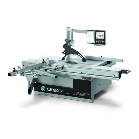
- Page 1 Operating Manual F45 ProDrive 1.6 /2016 0000010038 Translation of the original operating instructions...
-
Page 2: Table Of Contents
Table of contents Table of contents Foreword Identification Machine identification Certificates Marks of conformity Product description Marking, pictographs Intended use Dimensions and weights Auxiliary power/power requirements Emissions 3.5.1 Noise - characteristic values 3.5.2 Dust 3.5.3 Electromagnetic compatibility Ambient conditions Safety information 3.7.1 Operational safety 3.7.2... - Page 3 Table of contents 5.3.3 Rip fence 5.3.4 Cross-slide and crosscut fence 5.3.5 Sliding table 5.3.6 Electrical connection 5.3.7 Connecting the extraction system (customer side!) Basic machine setting 5.4.1 Swinging arm 5.4.2 Sub rollers on the sliding table 5.4.3 Main table 5.4.4 Cross-slide height 5.4.5...
- Page 4 Table of contents 6.6.3 Mitre fences 6.6.4 Dimension display unit DIGIT L 6.6.5 Digital angle and length display DIGIT LD 6.6.6 Rip fence with DIGIT X digital dimension display 6.6.7 Parallel cutting device 6.6.8 Workpiece hold-down device 6.6.9 Cross-slide width extension 6.6.10 Additional cross-slide 6.6.11...
- Page 5 Foreword Foreword Please read these operating instructions carefully before commissioning the machine. No liability will be accepted for any injury, damage or disruption to opera- tions resulting from failure to comply with these operating instructions! Persons operating this sliding table saw must have had sufficient instruc- tion and be suitably qualified! These operating instructions cannot be regarded as a binding type de- scription as the manufacturer may have carried out technical modifica-...
-
Page 6: Identification
Identification Identification Machine identification The type plate fitted to the machine frame serves for identifying the machine and other important machine data. Meaning of the stated descriptions: Fig. 2-1 Type plate Type: Machine designa- tion Number: Machine specific identification number Year of construc- Year of manufac- tion:... -
Page 7: Certificates
Identification Certificates Conformity declaration as defined by the machinery directive, Annex II 1A -Translation of the Original- Manufacturer: Wilhelm Altendorf GmbH & Co. KG Wettinerallee 43/45 32429 Minden Germany Person authorised to compile the Jörg Pöppelmann, Head of the mechanical design department technical documentation: Wilhelm Altendorf GmbH &... - Page 8 Identification EC prototype testing certificate Identification 0000010038-003- GB...
- Page 9 Identification Identification 0000010038-003- GB...
- Page 10 Identification GS test certificate Identification 0000010038-003- GB...
- Page 11 Identification Identification 0000010038-003- GB...
- Page 12 Identification DGUV Test Certificate Identification 0000010038-003- GB...
- Page 13 Identification Identification 0000010038-003- GB...
- Page 14 Identification C US-Certificate Identification 0000010038-003- GB...
-
Page 15: Marks Of Conformity
Identification Marks of conformity CE symbol GS symbol Wood dust appro- C US mark mark Identification 0000010038-003- GB... -
Page 16: Product Description
Product description Product description Marking, pictographs Danger warning Hand injury warning Laser beam warning Crushing risk warning Voltage warning Note: Wear ear pro- tection Intended use The sliding table saw and the workpiece guide equipment supplied with it are intended to be used for cutting wood and similar materials such as: •... - Page 17 Product description The sliding table saw and the workpiece guide equipment supplied with it are not intended to be used for cutting materials such as: • Sheet steel • Sheet brass • Sheet copper • Round wood without the use of a suitable clamping device Tools: •...
- Page 18 Repair work must be carried out by our own customer service or by an organisation that we have authorised. Only original ALTENDORF spare parts may be used for this. ALTENDORF will assume no warranty for any damage that is caused by using non-original spare parts.
- Page 19 Non-adherence may lead to knee injuries! Note! Any other use is deemed as unintended. ALTENDORF will not be liable for any kind of injury or damage that may result from such unintended use; the risk thereof is borne by the user alone.
- Page 20 Product description Foreseeable misuse: • Working with the safety hood swung up • Working with the safety hood swung away • Failure to use the push stick or push block for cuts < 120 mm • Moving the sliding table without using the handle •...
- Page 21 Product description Residual risk: Even when the machine is operated in accordance with its intended use and all pertinent safety regulations, the following residual risks may be encountered because of design changes caused by the intended use in question: • Contact with the main saw blade and the scoring blade in the cutting area, in particular when the saw blade is tilted in the -45°...
-
Page 22: Dimensions And Weights
Product description Dimensions and weights [mm] [kg] [kg] [kg] [kg] [kg] [kg] [mm] [mm] 2580x660x330 2060x960x500 2250 855-1282 970-1495 131-142 203-230 3330x660x330 2060x960x500 3000 855-1282 970-1495 131-142 203-230 3530x660x330 2060x960x500 3200 855-1282 970-1495 131-142 203-230 3730x660x330 2060x960x500 3400 855-1282 970-1495 131-142 203-230 4130x660x330... -
Page 23: Auxiliary Power/Power Requirements
RCMAs with an isolator (preferably) or by type-B RCDs (uni- versal-current-sensitive residual-current circuit breakers). The following devices can be used: Manufacturer: Doepke switching devices; these switching devices can also be purchased via Altendorf. • DFS4 040-4/0,30-B NK, release current 300 mA •... - Page 24 Product description Auxiliary power/power requirements Motor Voltage Frequency Nominal current Fusing Without/with scoring [kW] [Hz] blade 12.4 / 15.8 7.2 / 8.7 200 - 220 19.8 / 23.2 200 - 220 26.5 / 29.9 380 - 420 50/60 11.5 / 13.5 380 - 420 15.5 / 17.5 380 - 420...
-
Page 25: Emissions
Product description Emissions 3.5.1 Noise - characteristic values Sound power level Emission Tools [dB (A)] sound level at the workplace [dB (A)] Idling_____L = 87.3 Idling_____L =77.4 Circular saw blade Cutting__L = 96.6 Cutting__L = 84.0 300x3.2/96 WZ n = 3987 rpm Idling_____L = 101.3 Idling_____L... - Page 26 Product description Factors that influence the immission level at the workplace include the duration of exposure, room characteristics, other sources of noise such as the type and number of neighbouring machines, and other working processes involving noi- se emission. Product description 0000010038-003- GB...
-
Page 27: Dust
Product description 3.5.2 Dust The dust emission values – measured in accordance with the “Principles for Testing Dust Emission (Concentration Parameters) from Woodworking Machi- nes” issued by the German trade association's technical committee for wood – are below 2 mg/m When the machine is attached to a correctly functioning extraction system with an air speed of at least 20 m/s (measured after joining the two extraction con- nections) you can assume it is and will stay compliant with the technical refe-... -
Page 28: Ambient Conditions
Product description Ambient conditions Transport and storage The machine must not be used in an environment with explosive or corrosive gases. The ambient temperatures for transport and storage range from - 25° C to + 55° C, and + 70° C is permissible for a short time. The maximum air humidity must not exceed 90%, and condensation must be avoided in all cases. -
Page 29: Safety Information
Product description Safety information 3.7.1 Operational safety The operation of woodworking machines with a manual feed involves a high risk in the event of incorrect handling. Therefore always observe the safety in- formation that is summarised in this chapter as well as government and other industrial safety regulations (e.g. - Page 30 Such riving knifes can be obtained from the trade or directly from ALTENDORF. • Use an anti-kick device for insert cuts, e.g. the front of the clamping shoe.
- Page 31 Product description • Regular cleaning of the machine and, in particular, the main table, sliding table and guides (e.g. rip fence) is an important safety factor. Before star- ting this work, make sure that the machine cannot be switched on uninten- tionally.
-
Page 32: Safety Devices
Product description 3.7.2 Safety devices Altendorf's sliding table saws have been developed in compliance with Euro- pean standard DIN EN 1870-18 "Safety of woodworking machines – circular sawing machines –: circular saw benches (with and without sliding table) and dimension saws”. -
Page 33: Top Safety Hood/Riving Knife
Product description 3.7.3 Top safety hood/riving knife For a max. tool diameter of 450/500/550 mm: • Top safety hood fitted separately from the riving knife for max. saw blade diameter of 450/500/550 mm, available in a narrow and a wide format made of polycarbonate to optimally cover the section of the blade not requi- red for sawing above the machine table with a safeguard against lifting beyond the maximum cutting height of + 5 mm. -
Page 34: Handling Batteries / Accumulators
Measures for damage prevention The risk potential of lithium batteries is, in addition to the product design, prima- rily determined by the module or system capacity. The types used by Altendorf are low-capacity lithium batteries (batteries > 1 kg). The information for dama- ge prevention applies to both new and used batteries. - Page 35 Product description Source: VdS 3103 : 2012-06 (01) Lithium batteries - Excerpt of the GDV leaflet for damage prevention Product description 0000010038-003- GB...
-
Page 36: Definitions
Definitions Definitions Description of machine Fig. 4-1 Description of the sliding table saw Definitions 0000010038-003- GB... - Page 37 Definitions 1. Riving knife 2. Saw blade, protective hood 3. Protective hood support 4. Fixed guards beneath the table 5. Rip fence 6. Trimming hold-down device (clamping shoe) 7. Table insert 8. Machine table 9. Table length extension 10. Fixing elements 11.
-
Page 38: Terms
Definitions Terms Scoring Creation of a shallow cut in the surface of a workpiece, deep enough to pass through any coating on the workpiece, so as to prevent damage to the undersi- de when the main saw blade makes its cut. Scoring blade A blade that is located in front of the sawing blade, used to score the workpiece and rotate along with the feed direction. - Page 39 Definitions Definitions 0000010038-003- GB...
-
Page 40: Transport, Siting And Installation
Transport, siting and installation Transport, siting and installation Transport When transporting the sliding table saw by elevating truck or fork lift truck (forks only with unchangeable length), only lift the machine up slightly and secure it against tipping! Packaging The type of packaging depends on the type of transport. Unless otherwise con- tractually agreed, the packaging corresponds to the HPE guidelines establis- hed by Bundesverband Holzmittel, Paletten, Exportverpackungen e.V. -
Page 41: Safety Measures Before Use/Installation
Transport, siting and installation Safety measures before use/installation Installation site No special foundations are required at the installation site for the sliding table saw. The floor must have a load bearing strength suitable for the machine weight and should be flat and level. Select an installation site that provides enough clearance around the sliding ta- ble saw, allowing for the space requirements shown in the figure and the size of the workpieces to be cut. - Page 42 Transport, siting and installation Danger! Danger of crushing! • For operation with the max. workpiece weight, secure the machine against tilting! • Ensure that there is sufficient safety clearance from building parts and other machines! Transport, siting and installation 0000010038-003- GB...
- Page 43 Transport, siting and installation Fig. 5-2 Space requirement Dimension A: Manual adjustment PA: Cutting width + 280 mm Motor-driven adjustment PA: Cutting width + 360 mm Dimension B: Sliding table length + 360 mm Dimension C: Sliding table length + 290 mm; sliding table length + 30 mm with Dimension D: Crosscut fence: 1890 - max.
- Page 44 Transport, siting and installation Fixing A fixing element is provided on the side of the machine frame to ensure the ma- chine stays in position. Once the sliding table saw has been set up, loosen the screws and lower the fixing down to the floor. Then retighten the two screws. Transport, siting and installation 0000010038-003- GB...
-
Page 45: Installation
Transport, siting and installation Installation 5.3.1 Telescopic tube for swinging arm Assembly, telescopic tube Standard/Compact Fig. 5-3 Installing the telescopic tube [1] Undo the cheese head screw [2] Push in the telescopic tube from the front through the housing for the swinging arm [3] Insert and tighten the cheese head screw Transport, siting and installation 0000010038-003- GB... - Page 46 Transport, siting and installation Installing the telescopic tube, 4th axis Fig. 5-4 Swivelling arm, 4th axis [1] Support bolt [2] Plug-type connection plate, telescopic tube [3] Plug-type connection plate, swivelling arm housing Note! • The two plug-type connections have a different number of pins! •...
-
Page 47: Main Table Length Extension
Transport, siting and installation 5.3.2 Main table length extension Assembly of TPL 840 Fig. 5-6 Installing the main table length extension [1] TPL board [2] Support arm [3] Fastening screw M10 [4] Support screw [5] Stationary installed, adjusted bracket on the cast table top [6] Fastening screws for TPL on bracket Assembly steps: •... - Page 48 Transport, siting and installation Table top expansion 1600/2000 with base support: Fig. 5-7 TPL 1600/2000 [1] Support screws [2] Fastening screws [3] Adjustable feet Assembly steps: • Place the TPL onto the brackets on the table top and insert the fastening screws of the support arms into the holes on the table top face end.
-
Page 49: Rip Fence
Transport, siting and installation 5.3.3 Rip fence Fig. 5-8 Installing the measuring bar [1] Fit the measuring bar easily with M6x30 countersunk screws (1) [2] Knock a 6x45 clamping pin (2) through [3] Tighten the countersunk screws(1) Assembly of TPV Fig. - Page 50 Transport, siting and installation Assembly steps: • Carefully push the rip fence onto the round bar • Place the TPV onto the brackets on the table top and insert the fastening screws of the support arms into the holes on the table top face end. •...
-
Page 51: Cross-Slide And Crosscut Fence
Transport, siting and installation 5.3.4 Cross-slide and crosscut fence Cross-slide Installing the cross-slide The cross-slide must be attached to every point of the outer-lying round bar of the sliding table, and must be clamped. Assembly steps: - Place the supporting pipe of the cross-slide [1] onto the bolt [8] of the telesco- pic tube - Tilt the cross-slide to the sliding table, suspend and clamp using the eccentric lever [2];... - Page 52 Transport, siting and installation Cross-slide clamping mechanism WA/WGA/CNC crosscut fence UNO 90 Fig. 5-11 Clamping lever [1] Clamping lever [2] Safety locking mechanism [3] Stop, safety locking mechanism for displacing the cross-slide [4] Drill hole, safety locking mechanism for removing the cross-slide To push the cross-slide to other positions on the sliding table, undo the clam- ping lever [1] up to the stop of the safety locking mechanism.
- Page 53 Transport, siting and installation Cross-slide clamping, CNC crosscut fence DUO 90/DUO Flex Fig. 5-12 Cross-slide clamping, CNC crosscut fence DUO [1] Eccentric clamping lever [2] Safety locking mechanism To push the cross-slide to other positions on the sliding table, undo the clam- ping lever [1].
- Page 54 Transport, siting and installation Crosscut fence, 90° only Fig. 5-13 Installing the 90° crosscut fence 1. Place the crosscut fence on the cross-slide such that the clamping bolts [1] can be inserted in the grooves [2] 2. Tighten the clamping bolts [1], positioning is carried out by means of the tapered surfaces Changing the 90°...
- Page 55 Transport, siting and installation Crosscut-mitre fence Fig. 5-14 Crosscut-mitre fence operating elements [1] Clamping lever 90° position [2] Clamping degree scale [3] Clamping pivot point [4] Clamping lever, cross-slide / sliding table [5] Clamping, C profile Installing the standard crosscut-mitre fence / with DIGIT L + LD: •...
- Page 56 Transport, siting and installation Fig. 5-15 Installing the WGA [1] Clamping degree scale [2] Clamping pivot point [3] Ball bearing Transport, siting and installation 0000010038-003- GB...
- Page 57 Transport, siting and installation 90° clamping Fig. 5-16 90° clamping [1] Support roller [2] Clamping lever [3] 90° stop [4] Pressure piece on the clamping lever [5] Guide bolt(s) Fig. 5-17 Crosscut-mitre fence left-hand side [1] Clamping screw, telescopic extension [2] Guide groove for 90°...
- Page 58 Transport, siting and installation Crosscut-mitre fence WGA_LD Crosscut-mitre fence with digital angle and length measurement Fig. 5-18 WGA_LD [1] Clamping lever 90° position [2] Indexing bolt, angle measurement [3] Clamping pivot point [4] Clamping lever [5] Clamping, angle measurement [6] Clamping, C profile Assembly of the crosscut fence •...
- Page 59 Transport, siting and installation • Lower the crosscut-mitre fence so that the bolt enters the guide carriage hole • Turn in clamping screw [5] loosely • Push the T-nut with clamping screw [3] into the pivot • Swivel the WGA to its 90° position and clamp with clamping lever [1]. •...
- Page 60 Transport, siting and installation Fig. 5-20 90° clamping [1] Support roller [2] Clamping lever [3] 90° stop [4] Pressure piece on the clamping lever [5] Guide bolt(s) Fig. 5-21 WGA_LD, LH side [1] Clamping screw, telescopic extension [2] Guide groove, 90° position [3] Clamping piece, 90°...
- Page 61 Transport, siting and installation CNC crosscut fence Operating elements, CNC crosscut fence UNO 90 Fig. 5-22 CNC crosscut fence UNO 90 [1] Stop fence [2] Axis drive [3] Axis extension [4] Electrical connection [5] Clamping screws [6] Indexing bolt, extension [7] Clamping screw, extension [8] Clamping lever, cross-slide [9] Clamping, C profile...
- Page 62 Transport, siting and installation Extension Fig. 5-23 Extension, CNC crosscut fence UNO 90 [1] 1000 mm extension piece [2] Indexing bolt [3] Clamping screw Extension installation • Insert the extension into the guide until the indexing bolt engages • Tighten the clamping screw. •...
- Page 63 Transport, siting and installation Fig. 5-24 Extension installation [1] Locking hole, extension [2] Indexing bolt [3] Clamping, extension Transport, siting and installation 0000010038-003- GB...
-
Page 64: Sliding Table
Transport, siting and installation 5.3.5 Sliding table Fig. 5-25 Bottom carriage stop [1] Place the bottom carriage on the machine frame and push against the stop screws. [2] Screw on the bottom carriage using the outer fixing screws. [3] Only tighten the middle fixing screw loosely. Fig. - Page 65 Transport, siting and installation Fig. 5-27 Installing the top carriage [1] Carefully push on the top carriage making sure it is not skewed, watch the e-chain. [2] Carefully push the guide rails onto the double rollers. [3] Push the top carriage towards the left, all the way to the stop. Fig.
- Page 66 Transport, siting and installation Fig. 5-29 Central fixing [1] Tighten the central fixing screw. [2] Check that the sub-rollers are correctly adjusted. Fig. 5-30 Bracket on the bottom carriage [1] Fix the bracket to the bottom carriage with 3 screws. Transport, siting and installation 0000010038-003- GB...
- Page 67 Transport, siting and installation Fig. 5-31 Bracket on the bottom carriage Fig. 5-32 Position of e-chain [1] Place the bottom e-chain on the bracket on the bottom carriage. [2] Run the cable into the machine frame through the opening in the bottom carriage. Transport, siting and installation 0000010038-003- GB...
- Page 68 Transport, siting and installation Fig. 5-33 Fastening the e-chain [1] Screw the first link of the e-chain onto the bracket using 2 screws. Fig. 5-34 Switch cabinet [1] Connect the plug to the switch cabinet. [2] Tighten the cap nut. Warning! The connectors have 3 and 5 poles.
- Page 69 Transport, siting and installation Fig. 5-35 Fastening the e-chain / cable [1] Remove all the packing tape. [2] Screw on the cover profile. Transport, siting and installation 0000010038-003- GB...
-
Page 70: Electrical Connection
Transport, siting and installation 5.3.6 Electrical connection Warning! Dangerous electric voltage! All work on the electrical equipment, including connection to the mains supply, may only be performed by a qualified electrician. Disconnect the machine from the mains supply before working on the electrical equip- ment. - Page 71 Transport, siting and installation Fig. 5-37 Circuit diagram Transport, siting and installation 0000010038-003- GB...
- Page 72 Transport, siting and installation Designation Designation GL 1 Rectifier Main switch S 26 LASER option switch Main saw motor Scoring saw motor MR 1 Temperature monitor for main saw motor Sliding table safety switch EMERGENCY STOP button Temperature monitor for scoring saw motor Machine door/cover plate safety switch Multifunction module F 1 - F 2...
-
Page 73: Connecting The Extraction System (Customer Side!)
Transport, siting and installation 5.3.7 Connecting the extraction system (customer side!) Fig. 5-38 Bottom extraction connection Total extraction system connection D = 140 mm Vmin = 1150 m /h at 20 m/s Bottom extraction connection D =120 mm The hoses and Y-tube are not supplied as standard with the machine. The dust emission values –... - Page 74 Transport, siting and installation Note! Observe the following: • Make sure that the extraction system is switched on together with the machine. For this, you can use the existing potential-free contact (POT - refer to circuit diagram) or a current transformer installed in the supply line.
-
Page 75: Basic Machine Setting
Transport, siting and installation Basic machine setting Basic machine setting is carried out at our factory during final assembly. It may be necessary to correct the machine's basic settings due to removal of various assembly groups, and transport and installation on site. The machine elements to be checked are described below. -
Page 76: Sub Rollers On The Sliding Table
Transport, siting and installation 5.4.2 Sub rollers on the sliding table Check the sub-rollers Fig. 5-41 Sub-rollers The sub-rollers must run smoothly against the start slope at the start and end of the raceway. They should be set so that they can be held by hand with noticea- ble force and that they slip while the sliding table is moved. -
Page 77: Main Table
Transport, siting and installation 5.4.3 Main table Checking the main table Place a rip fence straight edge on the sliding table, and move the table into the middle position. Move the sliding table forward and backward; the main table must be approx. 1/10 mm lower. Adjusting the main table Release the lock nuts (1) of the 4 stay-bolts, adjust the main table, and tighten the lock nuts. -
Page 78: Cross-Slide Height
Transport, siting and installation 5.4.4 Cross-slide height Check Fig. 5-43 Checking the cross-slide height Push a piece of cardboard of approx. 0.5 mm thickness between the crosscut fence and the sliding table; it must be possible to move the cardboard freely in every position. -
Page 79: Setting Free Cut
Transport, siting and installation 5.4.5 Setting free cut Sliding table Definition: The sliding table, the saw blade and the rip fence are not parallel to each other, so the crosscut fence and the rip fence do not form a 90° angle. The sliding ta- ble runs to the left out of the direction, by a fraction of a millimetre. - Page 80 Transport, siting and installation Setting: Manually adjustable rip fence Fig. 5-45 Setting free cuts, standard rip fence • Undo the nuts on the bolts connecting the round bar and the table width extension • The degree of free cut on the rip fence can be altered by adjusting the middle lock nuts •...
-
Page 81: Angle Cut
Transport, siting and installation 5.4.6 Angle cut Checking the angle cut Before checking the angle cut, check the settings of the sliding table and of the swinging arm, and correct them if necessary. Carry out the check as follows: Fig. 5-47 Angle cut As the tool, use a sharp saw blade, D = 350 mm/ 3.5/2.5/72 teeth alternate be- vel at n = 5000 rpm. -
Page 82: 0° Setting Of The Saw Blade
Transport, siting and installation 5.4.7 0° setting of the saw blade Check: • Set the tilt adjustment to 0°. • Position 2 strips (approx. 100 mm wide) vertically in front of the crosscut fence, cut in this position and butt the cut surfaces against each other. •... -
Page 83: Operating
Operating Operating Working safely with the dimension saw 6.1.1 Cross-slide/crosscut fence Fig. 6-1 Cutting boards The crosscut fence can be installed at two positions on the cross-slide. Position 1: Cutting boards The operator presses the workpiece against the fence in the cutting direction. Fig. - Page 84 Operating Function description of the crosscut-mitre fence • The crosscut-mitre fence can be swung by 49° (angle indicated on scale), plus angle-dependent adjustable length compensation via a scale. • Ball bearings run in the sliding table groove, preventing the stop fence coming into the cutting plane when swung •...
- Page 85 Operating Length compensation Fig. 6-4 Length compensation scale By shifting the crosscut-mitre fence, the length dimension can be adjusted for the set angle. Changing the crosscut-mitre fence • Release the clamping screw and clamping lever • Push the crosscut-mitre fence to the 2nd position •...
-
Page 86: Rip Fence
Operating 6.1.2 Rip fence Fig. 6-5 Position of the clamping screw For cutting parallel, the rip fence is pushed up to the required dimension. The set dimension is read off from the edge of the aluminium profile. The dimension scale can be adjusted to the individual tool thickness after re- leasing the knurled screw. - Page 87 Operating The stop fence of the rip fence can be adjusted in the cutting direction and to the profile height. Clamp it in the required position with the top eccentric lever. For crosscutting short workpieces and for recessing or other work cycles during which offcuts can become jammed between the stop and the saw blade, the stop fence is moved forward until its rear end is in front of the saw blade.
-
Page 88: Double Roller Carriage
Operating 6.1.3 Double roller carriage Sliding table operating elements: Fig. 6-8 Sliding table operating elements, manual Fig. 6-9 Sliding table operating elements, TIP SERVO Operating 0000010038-003- GB... - Page 89 Operating Fig. 6-10 Sliding table operating elements, vacuum suction cups The vacuum suction cups are exclusively operated by means of the operating panel. Operating 0000010038-003- GB...
-
Page 90: Working Examples
Operating Working examples General information The Altendorf sliding table saw is a universal machine that can be used for va- rious saw cuts. However, the machine must be set up appropriately. Tools First, make sure that you only use saws in perfect condition, that the riving knife is correctly set and that the top protection hood is lowered close above the workpiece to be cut. - Page 91 Operating Edge cutting (trimming) Fig. 6-11 Edge cutting Tool: Circular saw blade for longitudinal cuts Work cycle: Fit the clamping shoe on the sliding table. Lay the workpiece with the hollow side down, and press underneath the clamping shoe. Push the workpiece forward by applying pressure with the ball of your right hand on the workpiece edge.
- Page 92 Operating Longitudinal cutting of narrow workpieces Fig. 6-12 Longitudinal cutting Workpiece width < 120 mm Tool: Circular saw blade for longitudinal cuts Work cycle: Set the rip fence to the required cutting width. Lower the top pro- tection hood according to the workpiece height. Push the workpiece (aligned along the fence) and sliding table forward, using the push stick in the vicinity of the saw blade, and push the parted workpiece beyond the riving knife.
- Page 93 Operating Work cycle: Set the aluminium straight edge of the rip fence to the low guide surface. Lay the workpiece on the sliding table and press against the rip fence with your left hand. Push the workpiece forward with the sliding table; use the push stick in the vicinity of the saw blade to push the strip beyond the riving kni- Crosscutting wide workpieces Fig.
- Page 94 Operating Concealed cutting, rebating Fig. 6-15 Concealed cutting Tool: Circular saw blade for fine cuts Work cycle: When rebating, select the cutting sequence so that the cut-out strip is produced on the side of the blade opposite the fence. Lower the protection hood onto the workpiece and ensure good workpiece guidance (left hand pres- ses the workpiece against the rip fence).
- Page 95 Operating Work cycle: Close the table opening with a table strip matched to the grooving tool. Set the tool to the required groove depth. Leave the riving knife in as a rear tool cover. When pushing forward, firmly press the workpiece onto the tab- le (otherwise danger of unintentional insert operation.).
- Page 96 Operating Crosscutting short and narrow workpieces Fig. 6-18 Crosscutting Tool: Circular saw blade for fine cuts Work cycle: Adjust the deflector wedge featuring a magnet (not part of the scope of supply) such that the workpiece cuts cannot touch the rising section of the saw blade.
- Page 97 Operating Dividing large boards Fig. 6-19 Dividing For this work cycle, the dimension can be set both on the rip fence and on the crosscut fence. If several pieces of the same size are to be cut from a large board, it is best to first cut off parallel strips at the rip fence and then cut them to the required dimension.
-
Page 98: Machine Operation
Operating Machine operation 6.3.1 Main switch Fig. 6-21 Main switch The main switch is located on the outside of the RH switch cabinet. Before turning on the saw drives, the main switch must be moved to setting I. The machine control unit carries out a self-test, after which the available axes and their current values are displayed. -
Page 99: Switching The Saw Drives On And Off
Operating 6.3.2 Switching the saw drives on and off Fig. 6-22 Switches for saw drives Warning! • Before switching on the machine, make sure that all protective devices required for the respective work cycle are attached and ope- rative. In addition, check that the saw blades are correctly fitted and that there are no workpieces or other objects in their vicinity. - Page 100 Operating Fig. 6-23 Switches for sliding table saw drives The drives can also be turned on and off with the switches on the sliding table (option). In addition, the machine can be switched off with one of the EMERGENCY STOP buttons. However, this possibility should only be used in case of an emergency.
-
Page 101: Setting The Speed
Operating 6.3.3 Setting the speed Three rotational speeds can be set for the main saw drive by moving over the V-ribbed belt: • 3000 / 4000 / 5000 rpm Changing the rotational speed Fig. 6-24 Changing the rotational speed [1] Switch off the drive. [2] Open the machine door. -
Page 102: Fitting The Main Saw Blade
Operating 6.3.4 Fitting the main saw blade AKE clamping system Warning! The following points must always be observed: Non-adherence may lead to severe injuries! • Do not fit any saw blades that are cracked or damaged in any way. • Only fit saw blades with a diameter between 250 and 550 mm. - Page 103 Operating 1. Switch off the drive. 2. Set the saw blade to the maximum cutting height and tilt to 0°. 3. Turn off the main switch. 4. Move the top carriage to the middle of the saw shaft, and unlock the lock at the saw blade centre by pressing the knob on the middle carriage.
- Page 104 Operating Fitting a milling tool In order to use a milling tool (max. cutting width 20mm), first proceed as descri- bed in point 1-8 in the previous section. Then proceed as follows: 1. Remove the riving knife, cushioning disc and screws in the centre table strip Fig.
- Page 105 Operating Warning! After changing a saw blade, always check that the riving knife is correctly set. Non-adherence to these points may lead to severe injuries of the opera- tor! • Select the riving knife according to the saw blade size and main blade thickness •...
-
Page 106: Saw Blade Recommendation
Operating 6.3.5 Saw blade recommendation Warning! Please note that only main saw blades with side holes can be fitted. This is necessary to prevent loosening of the saw blade mounting in the course of braking! • Do not use high-speed steel (HSS) saw blades! •... - Page 107 Operating 6.3.6 Table locking The sliding table interlock can lock the sliding table in any position, so that the workpiece can be pushed against the crosscut fence without the easy-running sliding table being set in motion unintentionally. It is actuated by means of a handle at the end of the top carriage.
-
Page 108: Screen Controls Prodrive
Operating Screen controls ProDrive Fig. 6-31 Screen controls ProDrive Actuate the green buttons to select the required setting; the symbol in question will then be shown in inverse format. Enter the dimensions via the numeric key- pad and press the yellow START button to carry out positioning. The operation can be interrupted at any time by pressing the STOP button. -
Page 109: Function Button Block
Operating 6.4.1 Function button block Fig. 6-32 Function keypad [1] Back to previous dimension [2] Program call-up [3] Vacuum carriage (option) [4] Delete input [5] Menu call-up [6] Calibration [7] Rotational speed adjustment VARIO (option) [8] Scorer (option) Operating 0000010038-003- GB... -
Page 110: Height Adjustment
Operating 6.4.2 Height adjustment Fig. 6-33 Height adjustment • Press the axis selection button for the cutting height; the symbol in the cut- ting height display is shown in inverse format. • Enter the required dimension via the numeric keypad; the new dimension is shown in inverse format. - Page 111 Operating Infinitely variable fine adjustment is possible by pressing the Plus or Minus button. Adjustment takes place in creep speed mode. Pressing the button for more than 3 seconds switches adjustment to rapid speed mode. Briefly tou- ching the Plus or Minus button causes adjustment of 0.1 mm. Operating 0000010038-003- GB...
-
Page 112: Tilt Adjustment
Operating 6.4.3 Tilt adjustment Fig. 6-34 Tilt adjustment Warning! Always observe the following points prior to tilting the saw blade: • Use the wide safety hood! • Clear the main table of any workpieces in the tilting area. • When cutting widths less than 180 mm, set the rip fence straight edge to the flat position. - Page 113 Operating Calibration • Press the axis selection button for tilt adjustment. • Press the Cal button for longer than 1 second; CAL will appear on the dis- play. • Enter the measured tilt angle via the numeric keypad. • Press the Cal button; the new tilt angle is shown on the display. Fig.
- Page 114 Operating Fig. 6-36 Rip fence dimension correction When the saw blade is tilted, the dimension of the rip fence may be changed by up to 1.5 mm. As soon as a dimension correction is necessary due to tilting, the correction dimension will be displayed in the third line from the top on the dis- play.
-
Page 115: Motor Driven Rip Fence (Option)
Operating 6.4.4 Motor driven rip fence (option) Fig. 6-37 Rip fence adjustment • Press the axis selection button for the rip fence; the symbol for the rip fence is shown in inverse format. • Enter the required dimension via the numeric keypad; the new dimension is shown in red. - Page 116 Operating Calibration • Press the axis selection button for the rip fence. • Press the Cal button for longer than 1 second; CAL will appear on the dis- play. • Enter the measured cutting width via the numeric keypad. • Press the Cal button;...
-
Page 117: Infinitely Variable Speed Adjustment (Option)
Operating 6.4.5 Infinitely variable speed adjustment (option) Fig. 6-39 Selection button for rotational speed adjustment • Press the axis selection button for VARIO; the following mask appears: Fig. 6-40 Selecting the rotational speed [1] The saw blade diameter of the saw blade currently fitted and its maximum permit- ted speed are displayed. - Page 118 Operating • Change the rotational speed in steps of 50 by pressing the + / - button, or enter the speed via the numeric keypad in units of five revolutions. • Save the rotational speed that has been set by pressing the START button, or select another speed level.
-
Page 119: Scoring Saw
Operating 6.4.6 Scoring saw Fig. 6-41 Selection button for scorer adjustment • Press the axis selection button for the scorer; the following display appears: Fig. 6-42 Adjusting the scorer [1] The cutting height of the scorer and the side position can now be defined with the aid of buttons F2 - F5. - Page 120 Operating Height adjustment: • Briefly touching the F2 / F3 buttons causes minimal adjustments. • Holding these buttons down causes bigger adjustments. • The height that has been set is saved when you exit the scorer function. When the scorer motor is on, the scorer is in the top position. Otherwise it is moved up when the function is invoked.
-
Page 121: Rapido Plus Scoring Saw
Operating 6.4.7 RAPIDO Plus scoring saw RAPIDO Plus is a 3-axis scoring system with motorised adjustment of the cut- ting height and the right and left-hand side of the scoring saw blade. All settings can be made while the machine is running, so they can be done very quickly. Press the axis selection button for the scorer;... - Page 122 Operating Note! The positions given for the saw blade sides are guide figures only. Adjustment: • Press the + or - button to change the dimension. • Enter the dimension on the numerical keypad and press the START button. Calibrating the scoring saw •...
- Page 123 Operating Setting the scoring saw blade • Setting the cutting height • Set the blade protrusion by pressing button 2. • Set the position of the right saw blade side • so that both cutting edges are congruent when a test cut is made. •...
-
Page 124: Cnc Crosscut Fence Uno
Operating 6.4.8 CNC crosscut fence UNO Fig. 6-45 CNC crosscut fence UNO To adjust the crosscut fence, actuate the function key and enter a new value. When you press the yellow START button, the dimension field changes colour. The value is displayed in green once the position is reached. If a manual rip fence is equipped, the correction values for the crosscut fence are displayed as a function of the tilt angle. - Page 125 Operating Infinitely variable fine adjustment is possible by pressing the Plus or Minus button. Adjustment takes place in creep speed mode. Pressing the button for more than 3 seconds switches adjustment to rapid speed mode. Briefly tou- ching the Plus or Minus button causes adjustment of 0.1 mm. Operating 0000010038-003- GB...
-
Page 126: Vacuum Clamping In The Sliding Table
Operating 6.4.9 Vacuum clamping in the sliding table Fig. 6-46 Vacuum table Actuate the remote control to cause the workpiece to be vacuum held or re- leased. During vacuum holding, the button turns from grey to green. Actuate the marked function key to access the vacuum table menu, where it is possible to configure the active suction cups. -
Page 127: 6.4.10 Menu
Operating 6.4.10 Menu Fig. 6-47 Main menu Pressing the function key Menu in the function keypad takes you to the main menu. User menu Fig. 6-48 User menu When the function key User menu is pressed, the respective mask appears. Operating 0000010038-003- GB... - Page 128 Operating Fig. 6-49 Operational performance of the axes When the function key Operational performance of the axes in the user menu is pressed, the respective mask appears. Basic settings Fig. 6-50 Basic settings When the function key Basic setting is pressed in the user menu, the respective mask appears.
- Page 129 Operating Fig. 6-51 Selecting a language When the function key Select language is pressed, the respective mask ap- pears. Use the Down arrow button to display additional languages that can be selected. Fig. 6-52 Technician level When the function key Technician level is pressed in the user menu, the res- pective mask appears.
-
Page 130: 6.4.11 Programs Function
Operating 6.4.11 Programs function Running programs Press the "Prog" button on the function keypad. The following mask appears: Fig. 6-53 Running programs A program can be called up by entering the two-digit program number. Button functions: • Button 1 <> Back to previous page •... - Page 131 Operating Changing programs Press button 5 in the "Run programs" function to call up the "Change pro- grams" function. Fig. 6-54 Changing programs Button functions: • Button 1 <> Back to previous page • Button 2 <> Up one line •...
- Page 132 Operating Creating programs Press button 5 in the "Change programs" function to call up the "Create pro- grams" function. Fig. 6-55 Creating programs Button functions: • Button 1 <> Back to previous page • Button 2 <> Next free program location •...
-
Page 133: Protection Hood
Operating Protection hood Fig. 6-56 Protection hood swung away Swing away the protection hood as follows: • Turn off the main switch and secure against turning on again • Actuate the release lever • Swing the protection hood away Warning! You may only work with the protection hood swung away in special cases and with increased caution, e.g. - Page 134 Operating Fig. 6-57 Normal working position [1] Unlocking/locking lever Note! After completing the work cycle, immediately swing the protection hood back into the normal working position and lock it with the lever. Pull the lever forward until it noticeably engages. Operating 0000010038-003- GB...
- Page 135 Operating Changing the protection hood sections Fig. 6-58 Swivel out the hood section When changing between wide and narrow, it is not necessary to completely ex- change the hood but only the respective hood section by means of a snap fit. For exchanging the hood section, press the red pusher down and swivel out the hood section.
- Page 136 Operating Protection hood, machine tilting to both sides Installing the wide protection hood, see photo and text on previous page. For tilting in the negative range (-), the protection hood is pulled out after unlo- cking the lever at the rail guide. Fig.
-
Page 137: Optional Modules
Operating Optional modules 6.6.1 Scorer, tilting to one side When processing boards coated on both faces, the scoring unit makes it possi- ble to cut without breakouts on the underside of the board. The scorer cuts into the material from below approx. 1-2 mm; then the main saw blade cuts through it. - Page 138 Operating Fig. 6-62 RAPIDO scoring tool Fitting the saw blade The description for fitting the saw blade applies both to two-part scoring blades and to RAPIDO scoring tools. Only use saw blades with a diameter of 120 mm and a hole diameter of 22 mm! •...
- Page 139 Operating Attention! The following must also be observed when using RAPIDO scoring blades with infinitely variable cutting width adjustment: • Failure to comply with the operating instructions inadmissibly redu- ces Health and Safety at Work and excludes any claims for liability. •...
- Page 140 Operating Adjusting the scoring blade for the RAPIDO scoring tool Fig. 6-63 Release the clamping screw. Fig. 6-64 Adjust the spindle. Note! Only use the supplied tools for adjustment work! • Release the clamping screw, approx. 2 turns. • Turn the spindle until the required dimension is reached. (1 turn = 0.5 mm) •...
- Page 141 Operating Replacing the scoring blade for RAPIDO Fig. 6-65 RAPIDO saw blades Remove the adjustment unit from the machine. It may be necessary to loosen the clamping screw because an excessively tight clamping screw can cause the adjustment unit to jam on the shaft! Dismantling Using the Allen wrench: •...
- Page 142 Operating • Fit a new saw blade, paying attention to the rotational direction and hole pattern: The circular saw blade (6) is in full contact with the flange (3) and the shoulder on the circular saw blade must point to the contact surface. •...
- Page 143 Operating Note! A red anodised table strip is integrated in the area of the scorer (optio- nally available with LED lighting). This strip marks the hazard zone of the scoring tool. Fig. 6-66 Red table strip (standard) Fig. 6-67 Red table strip with lighting (optional) Operating 0000010038-003- GB...
- Page 144 Operating RAPIDO - PLUS The 3-axis scoring system allows motorised positioning of the cutting height, width and cutting width. All settings can be entered via the keypad while the machine is running, and are shown on the display. Replacing saw blades Fig.
- Page 145 Operating Fig. 6-70 RAPIDO-Plus, fitting the saw blade [1] Undo the screws [2] Remove circular saw blade [3] Carefully clean the flange and screws [4] Fit a new saw blade, paying attention to the rotational direction and hole pattern! [5] Insert screws and tighten with a torque of 8.6 Nm [6] Proceed in the same manner for the other half of the adjustment unit Operating 0000010038-003- GB...
-
Page 146: Scorer, Tilting To Both Sides
Operating 6.6.2 Scorer, tilting to both sides The following scorer systems are available for machines tilting to both sides: Scorer diameter: 180 mm! Duet set Main saw blade and scorer blade ground to the same width in pairs RAPIDO-BS Width-adjustable scoring system with two saw blades, the spacing of which is adjustable 3-axis scorer In this case, the width and side adjustment is carried out electrically in the con-... -
Page 147: Mitre Fences
Operating 6.6.3 Mitre fences Single-sided mitre fence Fig. 6-71 Single-sided mitre fence The fence can be fitted quickly and easily to the sliding table with an eccentric clamping system. Dimension scales are inclined in order to stay in the opera- tor's field of vision. - Page 148 Operating The DUPLEX mitre fence can be infinitely adjusted from 0° to 90°. The circular scale with a radius of 350 mm has 0.25° graduation, allowing precise and fast setting of the mitre angle. The DUPLEX mitre fence can be fitted at any position of the sliding table due to its eccentric clamping system.
-
Page 149: Dimension Display Unit Digit L
Operating 6.6.4 Dimension display unit DIGIT L Fig. 6-73 DIGIT L The dimensions that have been set are displayed digitally in the 150 mm to 3200 mm range to an accuracy of ± 0.1 mm. The proximity sensor operates wear-free and is not sensitive to dust. A precise adjustment system is used for precision setting in 1/10 mm increments. - Page 150 Operating Power supply Power is supplied by a rechargeable battery. The charging state is shown in the bottom right hand corner of the display. The batteries can be recharged using the supplied charger. Changing the rechargeable battery Fig. 6-75 Changing the rechargeable battery for DIGIT L , DIGIT LD Fig.
- Page 151 Operating Basic setting / calibration of the display unit The basic setting of the display unit is needed in order to adapt the measuring system to the machine situation. Check and, if necessary, re-enter the basic settings following each tool change. How to proceed: •...
-
Page 152: Digital Angle And Length Display Digit Ld
Operating 6.6.5 Digital angle and length display DIGIT LD Fig. 6-78 Crosscut-mitre fence display unit WGA_LD The angle is shown in the display to an accuracy of 0.01° and the dimensions set in the 150 mm to 3200 mm range are shown in the display to an accuracy of ±0.1 mm. - Page 153 Operating The fence position is switched over on the cross-slide by pressing the button on the left hand side. Operating 0000010038-003- GB...
- Page 154 Operating Power supply Power is supplied by a rechargeable battery. The charging state is shown in the bottom right hand corner of the display. The batteries can be recharged using the supplied charger. Changing the rechargeable battery Fig. 6-80 Changing the rechargeable battery for DIGIT L , DIGIT LD Fig.
- Page 155 Operating Note! For information on how to handle batteries, see chapter 3.6.4 Operating 0000010038-003- GB...
- Page 156 Operating Basic setting / calibration of the display unit The basic setting of the display unit is needed in order to adapt the measuring system to the machine situation. Check and, if necessary, re-enter the basic settings following each tool change. How to proceed: •...
-
Page 157: Rip Fence With Digit X Digital Dimension Display
Operating 6.6.6 Rip fence with DIGIT X digital dimension display Fig. 6-84 Rip fence with Digit X The electronic measuring system with digital display and fine setting system ensures precise and fast setting of the rip fence. The display is always in the field of vision. - Page 158 Operating Fig. 6-86 Remove the housing with the display unit Note! For information on how to handle batteries, see chapter 3.6.4 Fig. 6-87 Undo the screws and remove the cover. Fig. 6-88 Change the batteries, ensuring correct polarity Operating 0000010038-003- GB...
- Page 159 Operating Basic setting of the display unit Fig. 6-89 Operating the Digit X The basic setting of the display unit is needed in order to adapt the measuring system to the machine situation. Check and, if necessary, re-enter the basic setting for each tool change.
- Page 160 Operating • Hold the + button down for more than 3 seconds; the display shows inches (or mm). • Release the + key; the display unit now shows the set dimension in inches (or mm). Operating 0000010038-003- GB...
-
Page 161: Parallel Cutting Device
Operating 6.6.7 Parallel cutting device Parallel cutting device Fig. 6-90 PALIN parallel cutting device Parallel cutting of long, narrow parts is done to the left of the saw blade. The PALIN and PALIN_D parallel cutting devices are good for this. In parallel cut- ting, the flip stop is set to the same dimension at the crosscut fence and at the PALIN. - Page 162 Operating PALIN_D with digital dimension display and precision setting system A precise adjustment system is used for precision setting in 1/10 mm increments. Both parallel cutting devices can be adjusted to a workpiece width of up to 900 mm. Operating 0000010038-003- GB...
- Page 163 Operating Alkali manganese batteries have an operating life of approx. 1 year. A battery capacity display provides a timely reminder of a battery change. We do not recommend the use of rechargeable batteries of any type as their voltage and capacity differ from that of alkaline batteries. As a result, the esti- mated operating life of approx.
- Page 164 Operating Basic setting of the display unit The basic setting of the display unit is needed in order to adapt the measuring system to the machine situation. Check and, if necessary, re-enter the basic settings following each tool change. The basic setting can only be carried out together with the tools used so it cannot be done at the factory.
-
Page 165: Workpiece Hold-Down Device
Now the workpiece is clamped by means of the threaded rod on the extension arm. Use the clamp handle to clamp or unclamp the workpiece. Klemmfix Fig. 6-93 Altendorf Klemmfix Operating 0000010038-003- GB... - Page 166 Operating Altendorf Klemmfix consists of two collets for fixing narrow and small workpie- ces on the sliding table. They securely hold workpieces from 0-70 mm. The col- lets can be used as required throughout the full length of the sliding table.
- Page 167 Operating Electro-pneumatic hold-down device Fig. 6-94 Electro-pneumatic hold-down device The electro-pneumatic hold-down device fixes the workpiece to the crosscut fence and operates with a clamping force of max. 1000 N at a pressure of 6 bar. The maximum clamping height is 90 mm. The safety cylinder only clamps the workpiece when the pressure plate is posi- tioned vertically in relation to the cylinder axis.
- Page 168 Operating Fig. 6-95 Remote control, hold-down device Movement up and down is controlled wirelessly via a small hand-held radio transmitter. The operating status of the hold-down device is shown on the switch box of the protection hood support. Yellow lamp: Cylinder pressurised White lamp: Cylinder not under tension If the remote control fails, the hold-down device can be controlled directly by pressing the illuminated push button.
- Page 169 Operating Pneumatic hold-down device Fig. 6-96 Pneumatic hold-down device The split hold-down beam can be controlled separately. This ensures optimum adjustment to differing workpiece lengths with one or both hold-down beams. The hold-down beam stroke is 80 mm; the customer-provided pneumatic con- nection is 6 bar.
- Page 170 Operating The entire length of the pressure beam is controlled via valve V2 (at the end). After actuation, the two segments of the pressure beam are lowered simultane- ously. The rubber coating of the hold-down beam prevents the workpiece from slipping.
- Page 171 Operating Vacuum fastening in the sliding table Fig. 6-97 Suction cup rows A vacuum is generated in one or more suction cup rows via a high-capacity va- cuum pump to reliably hold the workpiece on the sliding table. Each suction area can be individually controlled, the workpiece can be released at the press of a button.
-
Page 172: Cross-Slide Width Extension
Operating 6.6.9 Cross-slide width extension Fig. 6-98 Cross-slide width extension The cross-slide width extension is intended to facilitate work with large format or long workpieces. It extends the width of the workpiece support surface to max. 650 mm by means of two telescopic tubes. Long boards can be securely loaded and crosscut. -
Page 173: 6.6.10 Additional Cross-Slide
Operating 6.6.10 Additional cross-slide Fig. 6-99 Additional cross-slide Optional equipment for optimum support extension for large format or particu- larly unwieldy boards. The additional cross-slide can be easily fitted at any point of the sliding table due to its quick-action clamping system. Max. -
Page 174: 6.6.11 Laser Cutting Line Display
Operating 6.6.11 LASER cutting line display Fig. 6-100 Laser cutting line display The laser beam shows the run of the cutting line over a length of approx. 5000 mm. For trimming or cutting along a marked line (e.g. for stairs/steps) in parti- cular, valuable set-up time and material can be saved. - Page 175 Operating Aligning the laser beam with the cutting line Fig. 6-101 Aligning the laser At the factory the laser is set so that the beam is perpendicular and parallel to the sliding table. When the hood has been swung away and this has been followed by positio- ning, it is necessary to check and possibly correct the laser settings.
-
Page 176: 6.6.12 Coolant Spray Device
Operating 6.6.12 Coolant spray device Fig. 6-102 Coolant spray device To improve the cutting quality, we recommend the use of a coolant spray de- vice for plastics with a low melting point and for certain light metal alloys, espe- cially in conjunction with the infinitely variable speed adjustment. A sensor is fitted in the front table strip to detect the workpiece. -
Page 177: 6.6.13 Tip-Servo-Drive
Operating 6.6.13 TIP-SERVO-DRIVE Fig. 6-103 TIP-SERVO-DRIVE The drive serves to assist the operator during sawing and is activated as soon as the joystick fitted on the sliding table is actuated (pressing = forward, pulling = backward). Operation is carried out from the usual workplace of the machine upstream of the sliding table. -
Page 178: Cleaning/Care
Cleaning/care Cleaning/care Safety measures Warning! Please observe: • Always turn off the main switch and secure it against being turned on again before doing any maintenance work! Non-observance can lead to severe injuries! Note! Before using solvents and cleaning agents, make sure that these substances do not cause damage to the painted, anodised or galvanised surfaces as well as plastic parts. -
Page 179: Maintenance/Cleaning By The User
Cleaning/care Maintenance/cleaning by the user Note! Regular cleaning of the machine and the machine environment pro- longs the life of the machine, is prerequisite for perfect cutting results and reduces the risk of accidents. Pay attention to the following: • Machine table •... - Page 180 Cleaning/care Once a month: Sliding table Fig. 7-3 Remove dirt and resin residue from the guide of the sliding table using a cloth soaked in spirit Fig. 7-4 Remove dirt from the bottom of the guide of the sliding table Fig.
- Page 181 Cleaning/care Fig. 7-6 Cleaning of the sub-rollers of the sliding table Swinging arm Fig. 7-7 Open the swinging arm compartment Fig. 7-8 Clean the roller Cleaning/care 0000010038-003- GB...
- Page 182 Cleaning/care Fig. 7-9 Clean the roller from below Note! DO NOT APPLY OIL TO THE SWINGING ARM, just clean (dry)! Segments Fig. 7-10 Remove chips/dirt from the tilt segments (right and left-hand side) and spray with universal oil Cleaning/care 0000010038-003- GB...
- Page 183 Cleaning/care Fig. 7-11 Spray round bar. Subsequently move the block up and down. Every 6 months Sliding table Fig. 7-12 Spray guides with universal oil Note! Remove the oil from all lubricated points using a cloth! Note! Clean the monitor controls/screen using screen cleaning equipment such as a microfibre cloth, cleaning spray or cleaning pad (available from PC or mobile phone shops).
- Page 184 Cleaning/care Type of soiling Remove/clean with Chips and dust Vacuum cleaner, brush, cleaning cloth Resin residue Nitro thinner Resin residue on the sliding table guide Cleaning cloth, petroleum, spirit On the monitor Microfibre cloth, display cleaning spray or pad Avoidance of Necessary subsequent treatment Rust formation Universal oil...
- Page 185 Note! If you want to save time and money, sign up for the annual Altendorf inspection, the "check-up" for your sliding table saw. The lubrication measures will be carried out by our maintenance staff within the framework of the professional maintenance.
- Page 186 Cleaning/care Lubricating process: • Move the rip fence to the position ~ 800 mm (in this position, it is also pos- sible to access the lubricating nipple for the drive spindle). • Turn off the main switch and secure against turning on again. •...
- Page 187 Cleaning/care Lubricating nipple, saw unit Time interval: After travel of 100 m, a message is shown on the display indicating that relubri- cation of the height adjustment unit is necessary. Lubrication is necessary once a year, irrespective of the distance travelled. How to proceed: To relubricate, set the tilt of the saw blade to 45°...
- Page 188 Cleaning/care Fig. 7-15 Lubricating nipples (arrows), saw unit tilting to both sides Lubricating the scorer Note! Lubricating the scorer is only required for machines tilting to both sides (option). Fig. 7-16 Lubricating nipple (arrow), scorer Cleaning/care 0000010038-003- GB...
- Page 189 Cleaning/care Note! No relubrication of the saw shaft is necessary! Cleaning/care 0000010038-003- GB...
- Page 190 Cleaning/care Choice of lubricants Lubricant Manufacturer Aralub HL 2 Aral BEACON 2 Esso BP Energrease LS 2 ELF ROLEXA 2 Gulfcrown Grease No. 2 Gulf Marson EPL 2 Wintershall Shell Alvania grease R 2 Shell Extreme pressure-bearing grease LGEP 2 Way Lubricant 220 Texaco Tbl.
-
Page 191: Maintenance/Cleaning By Qualified Persons
Cleaning/care Maintenance/cleaning by qualified persons 7.3.1 Checking the winding shield Checking the winding shield The resistance of the PTC resistors must be checked in the motor terminal box by an electrician at least once a year. Resistance must be measured with a cold motor, and should be 750 ohms ±... -
Page 192: Faults/Problems/Troubleshooting
Faults/problems/troubleshooting Faults/problems/troubleshooting Machine diagnosis The display shows when limit switches have been actuated at protective de- vices and so on. There are two function groups. Function group 1: • Motor temperature • Machine door • Lower saw blade cover • EMERGENCY STOP button •... -
Page 193: Motor Overload Protection
Faults/problems/troubleshooting Motor overload protection Fig. 8-1 Motor overload protection The drive motors are protected against overload by a winding shield. This swit- ches a motor off automatically if it overheats. In the case of machines equipped with a scorer, the scorer drive is also switched off even if this motor was not overloaded. -
Page 194: Troubleshooting/Faults/Messages
Faults/problems/troubleshooting Troubleshooting/faults/messages Fault Cause Troubleshooting The machine cannot be The main switch is not Turn the main switch to switch position “I”. switched on. turned on. Power failure or phase Wait for power to be reinstated, or eliminate cause failure for loss of power, check factory fuses. - Page 195 Faults/problems/troubleshooting Fault Cause Troubleshooting The finished size of the Dimension scale for Reset the dimension scale: Cut a workpiece at the cut workpiece does not cutting width display is rip fence, precisely measure the cut width and posi- match the cutting width misadjusted.
- Page 196 Faults/problems/troubleshooting Fault Cause Troubleshooting Feed too low Increase the feed rate. Saw blade has too Change the saw blade. many teeth. Incorrect free cut Readjust the free cut. Break-outs in spite of Scorer not aligned with Readjust free cuts; the free cut should be almost “0”. scorer main saw blade Scoring blade too nar-...
- Page 197 Faults/problems/troubleshooting Fault message Cause Troubleshooting B000 - B063 Internal faults Request a service technician to check the function. Limit switch ES_MIN1 reached Limit switch ES_MIN2 reached Limit switch ES_MAX reached Fault, collision, fast shutdown Drive positioning fault Axis reference run error Perform new reference run Fresh oil lubricator empty Change cartridge...
- Page 198 Faults/problems/troubleshooting Fault message Cause Troubleshooting Brake unit fault: Mains contactor Request a service technician to perform a not in neutral position. repair. Operating error, incorrect riving Check rotational speed and riving knife posi- knife position or speed setting, e.g. tion. too fast for 450 mm saw blade.
-
Page 199: Electronic Brake Module
Faults/problems/troubleshooting Electronic brake module The main saw shaft is braked with an electronic brake module. This brake mo- dule is located in the contractor control housing, and is accessible when the rear panels have been removed.Braking is controlled in such a way that there is a high brake current at the beginning of braking. -
Page 200: Technical Data
Technical data Technical data Standard equipment Saw blade heights: Standard up to 450 mm Features Electromotive height and tilt adjustment 0 - 46 ° for the main saw blade, for til- ting in both directions from -46° to +46°, with automatic correction of the cutting height when tilting the saw unit, and with dis- play of tilt angle and cutting height. - Page 201 Technical data Saw blade dia- Standard Option: meter [mm] Extended cutting height 0° + 45° - 45° 0° + 45° - 45° 0 - 55 0 -30 0 -1 0 - 55 0 - 30 0 - 1 0 - 80 0 - 47 0 - 18 0 - 80...
- Page 202 Technical data Technical data: Main saw Tool holder diameter 30 mm Saw blade tilting range 0-46° Idling speed 4000 rpm Tool edge width max.20 mm Sliding table Sliding table cutting length See table Crosscut fence Crosscutting at 90° crosscut fence 3200 mm Rip fence Cutting width at rip fence...
- Page 203 Technical data Weight Machine weight, dependent upon equipment Approx. 1100 kg Electrical equipment Lockable main switch Contactor control with pushbutton operation Control voltage 24 VAC Rotational speed, tilt angle, cutting height Digital display Braking of main motor, monitoring of winding Electronic multifunction temperature module/frequency converter...
-
Page 204: Special Equipment
Technical data Special equipment Available special equipment Main saw drive Heavy-duty motors up to 11 kW (for machines tilting to one side) Infinite rotational speed adjustment (VARIO, adjustable in increments of 5, power for machines tilting to one side: 5.5kW, 7.5kW , power for machines tilting to both sides: 5kW and 6.5 kW) Sliding table Sliding table lengths from 2250 mm to 5000 mm... - Page 205 Technical data Available special equipment Pneumatic hold-down beam For sliding table length 2250 mm, clamping length 1975 mm For sliding table length 3000 mm, clamping length 2725 mm For sliding table length 3200 mm, clamping length 2925 mm For sliding table length 3400 mm, clamping length 3125 mm For sliding table length 3800 mm, clamping length 3525 mm Max.
-
Page 206: Maintenance And Repairs
Maintenance and repairs Maintenance and repairs 10.1 General Keeping a supply of the most important spare and wear parts on site is an im- portant prerequisite for the constant functioning and operating capability of the sliding table saw. We only accept a guarantee for original spare parts supplied by us. -
Page 207: Customer Service Addresses
Maintenance and repairs 10.2 Customer service addresses Wilhelm Altendorf GmbH & Co KG Service department Wettinerallee 43/45 D-32429 Minden Post office box D-32377 Phone: +49 571 9550222 Telefax: +49 571 9550111 e-Mail: service@altendorf.de www.altendorf.com Maintenance and repairs 0000010038-003- GB...
Need help?
Do you have a question about the F45 ProDrive and is the answer not in the manual?
Questions and answers