Table of Contents
Advertisement
Quick Links
Advertisement
Table of Contents

Related Manuals for InfiRay IRS-FB4 Series


Summary of Contents for InfiRay IRS-FB4 Series
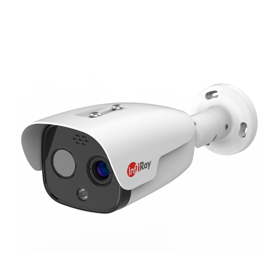
- Page 1 Dual-spectrum Network Bullet Camera User Manual V1.0.2 IRay Technology Co., Ltd.
-
Page 2: Important Safety Instructions
Important Safety Instructions In order to avoid danger or property damage, the following right usage rules are for you to follow. Please read the instructions carefully and rigorously follow the instructions before usage. The User Manual should be carefully kept after being read. It indicates that low or medium potential risk is existing. - Page 3 Dual-spectrum Network Bullet Camera User Manual ⚫ In order to make emergency power off when necessary, please install power-off equipment which is easy to use when installing the wires. ⚫ Please protect power lines from being treaded or pressed, especially the connecting points which are led from the plug, power socket or other unit.
- Page 4 Dual-spectrum Network Bullet Camera User Manual materials of the same quality. ⚫ Please do not press, vibrate violently or soak the camera during transportation, storage or installation. ⚫ It is advised to use the camera with lighting protector. ⚫ Soft dry cloth can be used to clean the device. For the dirt difficult to clean, please use soft cloth with little neutral detergent and then wipe dry.
-
Page 5: Table Of Contents
Dual-spectrum Network Bullet Camera User Manual Table of Contents Important Safety Instructions .............. I 1. Product Introduction ................. 1 1.1 Product Description ................1 1.2 Product Feature .................. 1 2. Operation Guide .................. 2 2.1 Preparations ..................2 2.2 Brief Introduction of Interface ............3 2.2.1 Log in .................. -
Page 6: Product Introduction
1.2 Product Feature ⚫The latest InfiRay® 12μm IR thermal imaging detector, advanced IR vision algorithm, more distant and clearer image. ⚫Function of front-end independent temperature measuring; installed with professional temperature measuring analysis tools and multiple linkage alarm... -
Page 7: Operation Guide
Dual-spectrum Network Bullet Camera User Manual ⚫Function of intelligent behavior analysis, such as regional invasion detecting, boundary violation detecting, entering and leaving area detecting and left items detecting, etc. ⚫One-piece shell, with outdoor protection class IP66. ⚫ONVIF standard interface protocol supported, available SDK, secondary development and third-party platform connection supported. -
Page 8: Brief Introduction Of Interface
Dual-spectrum Network Bullet Camera User Manual 5) Install the plug-in after quitting the antivirus software such as 360. 2.2 Brief Introduction of Interface 2.2.1 Log in http://192.168.1.19 into the address bar of the IE browser, the login 1)Input interface is shown in the following figure: Figure 2.1 Login Page 2)Read carefully about the web prompt. -
Page 9: Brief Introduction Of Preview Interface
Dual-spectrum Network Bullet Camera User Manual 4)Input Username:888888(factory default, administrator) or 1(normal user); 5)Input password: 888888(factory default, administrator) or 1(normal user) 6)Click “OK” to enter the preview of the video server. As is shown in the following figure: Figure 2.2 Preview Page 2.2.2 Brief Introduction of Preview Interface Real-time Preview Option: 【Network Mode】:TCP and MultiCast, you can choose unicast preview or... - Page 10 Dual-spectrum Network Bullet Camera User Manual channel 2. 【Alarm Output Control】:click ,the icon turns red, then you can manually control the alarm output of certain channel. click again, then you can manually stop the alarm output of certain channel. 【Palette】:choose palette pull-down menu, the device supports 18 kinds of palette, you can choose to switch.
- Page 11 Dual-spectrum Network Bullet Camera User Manual 【Snapshot】:click button, you can save the current screen image into the d:\of the local computer in *.Bmp format. The way of naming is: device name+channel NO. + Time, for example “D:\20190411\***_1_105925.bmp”, the size of the image file is consistent with the image resolution. If there is overlaying characters and time on the preview image, then the same will be displayed in the snapshot picture.
-
Page 12: Introduction Of Playback Interface
Dual-spectrum Network Bullet Camera User Manual previous size. 【Delay】click to set the image delay level, the bigger the delay number is, the longer the image delay time is, but the image continuity is better, the background of “delay” button chosen will turn white. 2.2.3 Introduction of Playback Interface 【Playback】... -
Page 13: Introduction Of Settings Interface
Dual-spectrum Network Bullet Camera User Manual 2.2.4 Introduction of Settings Interface 【Settings】: click “settings” to enter into interface of parameter setting, see the following figure: Figure2.4 Settings Page The settings include basic, network, channels, infrared, alarm and storage. 2.3 Settings 2.3.1 Basic setting 2.3.1.1 Device Information Click “Device Name”, the corresponding setting will appear beneath. - Page 14 Dual-spectrum Network Bullet Camera User Manual Enter the device name and click ok, then the device name can be revised. 2.3.1.2 Language Switch Click “Language Settings”, the setting page will be unfolded beneath. Figure 2.6 Language Switch Page Choose the language you want, click ok, then the language can be revised. 2.3.1.3 Date &Time Synchronization Click “Date &Time”, the corresponding setting will be unfolded beneath.
- Page 15 Dual-spectrum Network Bullet Camera User Manual synchronous with the PC time after the configuration. Figure 2.8 Date& Time Page (NTP Server) Page 2.3.1.4 Video Format Click “Video Format”, the corresponding setting will be unfolded beneath, see the following figure: Figure 2.9 Video Format Page Choose PAL or NTSC, click ok, the parameter modification can take effect immediately and it is only valid for analog video output.
- Page 16 Dual-spectrum Network Bullet Camera User Manual 2.3.1.6 User Management Click “User Management”, the corresponding setting will be unfolded beneath, see the following figure: Figure 2.11 User Management Page The default administrator name and password is admin/admin, and they can be modified, click “ok” to confirm; in order to browse live video, you need to re-login after the name and password are changed.
- Page 17 Dual-spectrum Network Bullet Camera User Manual 2.3.1.7 System Maintenance Click “Scheduled Reboot”, the corresponding setting will be unfolded beneath, choose on/off, see the following figure: Figure 2.12 System Maintenance Page Enter the reboot time, for example one hour and five minutes, click “ok”, this can make the video server reboot at an appointed time each day.
-
Page 18: Network Set
Dual-spectrum Network Bullet Camera User Manual 2.3.1.9 System Upgrade Click “System Upgrade”, the corresponding setting will be unfolded beneath, see the following figure: Figure 2.14 System Update Page Click “Browse”, select the corresponding *.itm or *.rom file which needs to be upgraded, click “ok”;... - Page 19 Dual-spectrum Network Bullet Camera User Manual Figure 2.15 IP Address& Port Page The IP Address, subnet mask, gateway, web port, data transfer port, remote host address, remote host port, multicast address and port can be changed. The start of web service port,DHCP and PPPOE dial-up services can also be set, click “ok”, then click “storage parameters”...
- Page 20 Dual-spectrum Network Bullet Camera User Manual and update interval, click “ok”. Enter domain name in IE address bar, the domain name is transferred successfully if the device can be accessed normally. 2.3.2.3 UPNP Click “UPNP”, the corresponding setting will be unfolded beneath, see the following figure: Figure 2.17 UPNP Page Connect the device to the Router with UPNP function, the Web Service Port,...
-
Page 21: Channels Parameter Set
Dual-spectrum Network Bullet Camera User Manual The default status is ONVIF on. 2.3.3 Channels Parameter Set 【 Channels 】 : choose “channels”, the corresponding parameters will be unfolded beneath, see the following figure: Figure 2.19 Page of Channels Parameter Set 2.3.3.1 Character Overlay Click “Character Overlay”, the corresponding setting will be unfolded beneath, see the following figure:... - Page 22 Dual-spectrum Network Bullet Camera User Manual it can be set into one line which could be written in Chinese characters, uppercase and lowercase, figures and special characters, set the coordinate to be displayed; choose time format, set the coordinate to be displayed; check “Frame Rate”...
- Page 23 Dual-spectrum Network Bullet Camera User Manual 2.3.3.3PTZ Protocol Connect the RS485 interface to the device with PTZ, select “PTZ Protocol”, the setting page will be unfolded beneath, see the following figure: Figure 2.22 PTZ Protocol Page Check “Update PTZ Protocol”, click “Select File(*.ptz)” to select the PTZ protocol which needs to be updated, then click “ok”...
- Page 24 Dual-spectrum Network Bullet Camera User Manual ➢ Press up/down/left/right button, the device can rotate according to the operated direction; ➢ Change the PTZ speed, then control the PTZ rotation, the device can rotate according to the set speed; ➢ Click “zoom+” and “zoom-”, which can zoom in or zoom out the image ➢...
- Page 25 Dual-spectrum Network Bullet Camera User Manual preview interface turns black and white; switch from black and white to color, the optical image in the preview interface turns colorful. 3. The supplement lamp will be turned on or turned off through on/off button. Switch “Day/Night Conversion Mode”...
-
Page 26: Infrared Parameters Setting
Dual-spectrum Network Bullet Camera User Manual Figure 2.26 Visible Anti-flicker Page If flicker appears on the preview image, then change the “Visible Anti-Flicker” setting. 2.3.4 Infrared Parameters Setting 【Infrared】:select “infrared”,the corresponding setting will be unfolded beneath, see the following figure: Figure 2.27 Page of Infrared Set 2.3.4.1DDE Select “DDE”, the corresponding setting will be unfolded as following:... - Page 27 Dual-spectrum Network Bullet Camera User Manual Figure 2.28 DDE Page Start DDE to adjust image display. 2.3.4.2 Image Gain Switch Select “Image Gain, the Image Gain is shown as the following figure. Figure 2.29 Image Gain Page Switch “Image Gain”, the temperature measurement range of high gain is -20~150℃, the temperature measurement range of low gain is 0-500℃.
- Page 28 Dual-spectrum Network Bullet Camera User Manual 2.3.4.3 Image Temperature Width Select “Image Temperature Width”, the following parameters will be displayed. See the figure below: Figure 2.30 Image Temperature Width Page Manual Enable: the temperature width of the IR image can be set manually, set “Threshold-Low”...
- Page 29 Dual-spectrum Network Bullet Camera User Manual Figure 2.31 Global Temperature Measurement Page Parameters related to temperature measurement: the temperature measurement parameters can be adjusted, ambient temperature, distance, emissivity can be set. Global Temperature OSD: the global temperature measurement results will be displayed on the top left corner after “Global Temperature OSD”...
- Page 30 Dual-spectrum Network Bullet Camera User Manual Palette OSD: the palette bar on the right will be overlapped on the image after “Palette OSD” is checked. It will not be displayed if “Palette OSD” is unchecked. Cursor OSD: the highest temperature cursor and lowest temperature cursor will be overlapped on the image after “Cursor OSD”...
- Page 31 Dual-spectrum Network Bullet Camera User Manual OSD Enable: OSD will overlap, for example, the region temperature on the left (Area1:max:32.7 min:23.6 avg:24.7, cen: 25.4) and the region drawing box will overlap, the information will not be displayed if “OSD Enable” is unchecked.
- Page 32 Dual-spectrum Network Bullet Camera User Manual Horizontal Offset:it can adjust the horizontal offset of the visible light and make it align with IR horizontally. Vertical Offset: it can adjust the vertical offset of the visible light and make it align with IR vertically. 2.3.4.7 Intelligent Analysis Choose “Intelligent Analysis Rules Settings”, the following parameters will be displayed beneath, see the following figure:...
-
Page 33: Alarm Set
Dual-spectrum Network Bullet Camera User Manual Figure 2.35 Intelligent Analysis Advanced Parameters At most 4 shielded area can be drawn, the shielded area can be deleted, intelligent analysis is not performed on shielded area. The target filter of intelligent analysis can be set. The sensitivity and background update speed of intelligent analysis can be revised. - Page 34 Dual-spectrum Network Bullet Camera User Manual Figure 2.36 Page of Alarm Set 2.3.5.1 Sensor Detection Schedule Settings Click “sensor detection schedule setting”, the corresponding settings will be unfolded beneath, see the following figure: Figure 2.37 Sensor Detection Schedule Settings Page Start Sensor Detection: to start function of sensor detection;...
- Page 35 Dual-spectrum Network Bullet Camera User Manual Sensor Status: the alarm should be triggered with mode on(alarm input and ground short connected); the video server will always on alarm state with mode off, the alarm will stop after the alarm is triggered (alarm input and ground short connected);...
- Page 36 Dual-spectrum Network Bullet Camera User Manual Figure 2.38 Temperature Abnormality Alarm Detection Region: support full-screen, region 1 -region 6; Regional Alarm Enable: to start the function of regional alarm detection; Threshold Type: above threshold -high, below threshold-low/between threshold-high and threshold-low/outside threshold -high and threshold-low; Sensor Status: the alarm should be triggered with mode on(alarm input and ground short connected);...
- Page 37 Dual-spectrum Network Bullet Camera User Manual Figure 2.39 Fire Alarm Detection Page Fire Point Enable: to start the function of fire point detection. Temperature Threshold of Fire Point: set temperature threshold of fire point detection, which will detect whether the temperature display of the full screen exceeds the temperature threshold;...
- Page 38 Dual-spectrum Network Bullet Camera User Manual Trigger Server-end Snapshot: linkage front-end device snapshot, the snapshot will be stored in the front-end devices, such as SD card; Trigger Alarm Output: to start linkage alarm output. 2.3.5.4 Temperature Difference Alarm Detection Click “Temperature Difference Alarm Detection”, the corresponding setting will be unfolded beneath, see the following figure: Figure 2.40 Temperature Difference Alarm Detection Page Group No.: support group1-group 6;...
- Page 39 Dual-spectrum Network Bullet Camera User Manual highest/lowest/average temperature between region A and region B; Threshold Type: above threshold (the temperature difference between region A and region B exceeds the set threshold)/below threshold (the temperature difference between region A and region B is within the set threshold); Temperature Difference Threshold: to set the threshold temperature;...
- Page 40 Dual-spectrum Network Bullet Camera User Manual Time Period Detection: support 7 time period detection set. Trigger Server-end Recording: linkage front-end device recording, the recording will be stored in the front-end device, such as SD card; Trigger Server-end Snapshot: linkage front-end device snapshot, the snapshot will be stored in the front-end devices, such as SD card;...
-
Page 41: Storage Set
Dual-spectrum Network Bullet Camera User Manual Figure 2.43 No Server-end Storage Alarm Page Enable Alarm: to start the function of no hard disk detection; Trigger Alarm Output: to start linkage alarm output. Image Icon Overlay: to trigger linkage image icon in preview image. Click “Server-End Storage Error Alarm”, the corresponding settings will be unfolded beneath, see the following figure: Figure 2.44 Server-end Storage Error Alarm Page... - Page 42 Dual-spectrum Network Bullet Camera User Manual Figure 2.45 Storage Page 2.3.6.1Server-End Snapshot Parameters Click “Server-End Snapshot Parameters”, the corresponding settings will be unfolded beneath, see the following figure: Figure 2.46 Page of Server-end Snapshot Parameters Snapshot Image Quality: to set the snapshot image quality, Channel 01 and Channel 02 are optional;...
- Page 43 Dual-spectrum Network Bullet Camera User Manual 2.3.6.3 Server-End Storage Device Click “Server-End Storage Device” the corresponding settings will be unfolded beneath, see the following figure; Figure 2.48 Page of Server-end Storage Device Server-End Storage Device Format. Only one hard disk can be formatted, if connected with several hard disks.
Need help?
Do you have a question about the IRS-FB4 Series and is the answer not in the manual?
Questions and answers