
Subscribe to Our Youtube Channel
Related Manuals for THORLABS INT-POL-1300


Summary of Contents for THORLABS INT-POL-1300
- Page 1 Operation Manual Thorlabs Instrumentation Balanced polarization diversity detector for PS-OCT INT-POL-1300...
- Page 2 Date: April 5, 2019 Copyright © 2018, Thorlabs GmbH...
-
Page 3: Table Of Contents
4.3 Repair Appendix 5.1 Technical Data 5.2 Mechanical Drawings 5.3 Warranty 5.4 Certifications and compliances 5.5 Thorlabs “End of Life” Policy (WEEE) 5.5.1 Waste treatment on your own responsibility 5.5.2 Ecological background 5.6 List of Figures 5.7 List of Acronyms... - Page 5 We and our international partners are looking forward to hear from you. Thorlabs GmbH This part of the instruction manual contains every specific information on how to handle and use the INT-POL-1300. A general description is followed by explanations of how to operate the unit. Attention...
-
Page 7: Overview
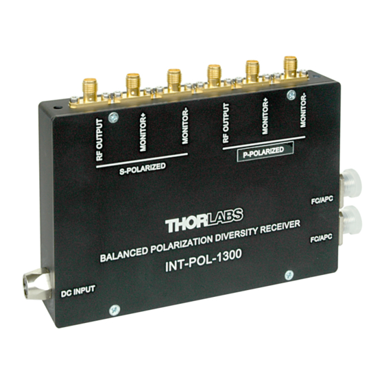
1 Overview 1 Overview The Thorlabs INT-POL-1300 is a subassembly to be used in polarization sensitive swept source Fourier domain OCT systems and other applications. It contains two polarization beam splitters and two balanced detectors. The S and P polarization states of the optical input signals are split using polarization beamsplitters (PBS). -
Page 8: Safety
The unit must not be operated in explosion endangered environ- ments! Only with written consent from Thorlabs GmbH may changes to sin- gle components be carried out or components not supplied by Thorlabs GmbH be used. This precision device is only dispatchable if duly packed into the complete original packaging including the plastic form parts. -
Page 9: Getting Started Quickly
Please check prior to operation, if the indicated line voltage on the power supply matches with your local mains voltage! NOTE If you want to use your own power supply, you can ask Thorlabs for an appropriate power connector cable. 2.2 Setup ... -
Page 10: First Operation
2.3 First Operation Please note, that all fiber connectors must have a FC/APC connector! Connect the INT-POL-1300 to your OCT setup, for further details please refer to section 3.4 Basic Measurement Setup. For balanced operation (optimum noise suppression), the power at each de- tector pair has to be the same. - Page 11 To prevent saturation of the amplifier keep the optical input power less than the saturation power listed in specification. Attention Refer to the specification and pay attention to the optical damage threshold! Exceeding these values will permanently destroy the detectors! INT-POL-1300 / page 5...
-
Page 12: Detailed Description
3 Detailed Description 3 Detailed Description 3.1 General Principle of Operation The Thorlabs INT-POL-1300 is a subassembly to be used in polarization sensitive swept source Fourier domain OCT systems and other applications. It contains two polarization beam splitters and two balanced detectors. -
Page 13: Optical Input And Detector Response
The internal fiber network is carefully length-matched for both SOP to achieve maxi- mum possible common mode rejection ratio CMRR (maximum noise suppression). INT-POL-1300 uses pigtailed InGaAs PIN photodiodes. Figure 3 shows a typical responsivity curve for this photodiode type. -
Page 14: Electrical Outputs
The 3 dB bandwidth of the RF OUTPUT signal is DC-15 MHz. Figure 4 shows a typical frequency response curve of INT-POL-1300 RF OUTPUT signal. For this measurement a test signal was applied to one input port only. - Page 15 The 3 dB bandwidth of the MONITOR signal is DC-5 MHz. Figure 4 shows a typical frequency response curve of INT-POL-1300 MONITOR signal. For this measurement a test signal was applied to one input port only. MONITOR outputs can be used to measure RF modulated signals on each detector separately.
-
Page 16: Basic Measurement Setup
3 Detailed Description Frequency (MHz) Figure 5: INT-POL-1300 MONITOR output frequency response 3.4 Basic Measurement Setup A measurement setup for Polarization Sensitive OCT is shown in Figure 6. Figure 6 Schematic setup for PS-OCT C Collimator; ILP: in-line polarizer; PC: Polarization Controller; M: Mirror; SS Swept Source, VA Varia-... - Page 17 The polarization controller in front of the input enables polarization adjustment of the signal to balance it at the S- and P- balanced detector. Data processing calculates the phase retardation between the two channels at different sample depth. INT-POL-1300 / page 11...
-
Page 18: Maintenance And Repair
4.2 Cleaning To clean the INT-POL-1300 housing, use a mild detergent and damp cloth. Do not soak the unit in water or use solvent based cleaners. It is not recommended to remove FC adaptors to clean the inner FC/APC connectors. -
Page 19: Repair
4 Maintenance and Repair 4.3 Repair There are no serviceable parts in the INT-POL-1300 or power supply. The INT-POL- 1300 does not contain any components to be repaired by the user. If any malfunction should occur or you suspect a problem, please contact Thorlabs GmbH for repair return instructions. -
Page 20: Appendix
SMA, 50 Ω DC Offset ±10 mV (max.) ±12 V, 250 mA Power Supply *difference between two optical powers on a detector pair All accuracy data are valid at 23 ± 5°C and 45 ±15% humidity INT-POL-1300 / page 14... -
Page 21: Mechanical Drawings
5 Appendix 5.2 Mechanical Drawings INT-POL-1300 / page 15... -
Page 22: Warranty
5 Appendix 5.3 Warranty Thorlabs GmbH warrants material and production of the INT-POL-1300 for a period of 24 months starting with the date of shipment. During this warranty period Thorlabs GmbH will see to defaults by repair or by exchange if these are entitled to warranty. -
Page 23: Certifications And Compliances
Compliance demonstrated using high-quality shielded interface cables shorter than or equal to 3 me- ters. Emissions, which exceed the levels required by these standards, may occur when this equipment is connected to a test object. Replaces 73/23/EEC, amended by 93/68/EEC. INT-POL-1300 / page 17... -
Page 24: Thorlabs "End Of Life" Policy (Weee)
5.5.1 Waste treatment on your own responsibility If you do not return an “end of life” unit to Thorlabs, you must hand it to a company specialized in waste recovery. Do not dispose of the unit in a litter bin or at a public waste disposal site. -
Page 25: Ecological Background
The intent of the WEEE directive is to enforce the recycling of WEEE. A controlled recycling of end of live products will thereby avoid negative impacts on the environ- ment. Figure 7: Crossed out “wheelie bin” symbol INT-POL-1300 / page 19... -
Page 26: List Of Figures
5 Appendix 5.6 List of Figures Figure 1: Switchable power supply for 100 V, 120 V, or 230 V ........4 Figure 2: Functional block diagram of the INT-POL-1300 ........... 6 Figure 3: INT-POL-1300 detector responsivity ............7 ... -
Page 27: Addresses
+49 (0) 81 31 / 5956-0 Fax: +49 (0) 81 31 / 5956-99 Email: europe@thorlabs.com Web: www.thorlabs.com Thorlabs, Inc. 56 Sparta Avenue Newton, NJ 07860 Sales and Support Phone: 1-973-579-7227 Fax: 1-973-300-3600 Email: sales@thorlabs.com Email: techsupport@thorlabs.com Web: www.thorlabs.com INT-POL-1300 / page 21... - Page 28 3-6-3, Kitamachi, Nerima-ku, Tokyo 179-0081 Japan Sales and Support Tel: +81-3-6915-7701 Fax: +81-3-6915-7716 Email: sales@thorlabs.jp Web: www.thorlabs.jp Please call our hotlines, send an Email to ask for your nearest distributor or just visit our homepage http://www.thorlabs.com INT-POL-1300 / page 22...
Need help?
Do you have a question about the INT-POL-1300 and is the answer not in the manual?
Questions and answers