Table of Contents
Advertisement
Quick Links
Advertisement
Table of Contents

Subscribe to Our Youtube Channel
Related Manuals for BIRO TRUE-LEFT 3334TL Series


Summary of Contents for BIRO TRUE-LEFT 3334TL Series
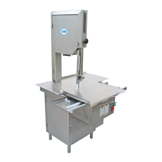
- Page 1 MODEL 3334TL & 3334-4003TL SERIES POWER MEAT SAW OPERATING AND SERVICE MANUAL REVISED - SERIAL No.1,000 ON TRUE-LEFT Model 3334SS-4003FH-TL as shown IMPORTANT NOTICE This Manual contains important safety instructions which must be strictly followed when using this equipment.
-
Page 3: Table Of Contents
TABLE OF CONTENTS PAGE NOTICE TO OWNERS AND OPERATORS ..........SAFETY TIPS . -
Page 4: Notice To Owners And Operators
Warnings related to possible damage are indicated by: BIRO also has provided a wall chart to be posted near the equipment. If any warning label, wall chart, or Manual becomes misplaced, damaged, or illegible, please contact your nearest Distributor or BIRO directly for a replacement. -
Page 5: Safety Tips
BEFORE Removing Shrouds, Removable Guards, Covers, Doors, Fences or Panels for Cleaning, Servicing or Any Other Reason. NEVER Leave Machine Unattended While the Saw is Running. PROMPTLY REPLACE Any Worn or Illegible Warning Labels. USE ONLY BIRO Parts and Accessories Properly Installed. -
Page 6: Installation
NEVER Operate Without all Warning Labels Attached and Wall Chart Posted. NEVER Leave Machine Unattended While the Saw is Running. USE ONLY BIRO Parts and Accessories Properly Installed. 1. Read this Manual thoroughly before installation and operation. Do not proceed with installation and operation if you have any questions or do not understand anything in this Manual. - Page 7 5. The V-belt is packed loose in machine to prevent deformation, and must be installed on pulleys at time of wiring motor. Double V-belts are shipped installed on machine. 6. The BIRO Manufacturing Company is not responsible for permanent wiring, connection or installations. NOTE TO OWNER AND ELECTRICIAN: IF THIS MACHINE IS NOT CORD...
-
Page 8: Warning Labels For Power Saws
15. Check placement of all warning labels, wall chart and Manual. Machine is ready for trained operators to process product. 16. Contact your local Distributor or BIRO directly if you have any questions or problems with the installation or operation of this machine. -
Page 9: Operation
OPERATION SHARP MOVING BAND TYPE SAW BLADE TO AVOID SERIOUS PERSONAL INJURY ONLY Properly Trained Personnel Should Use This Equipment. ALWAYS Keep Hands Clear of Band Type Saw Blade and Other Moving Parts. NEVER Operate with Saw Guard on Saw Guide Bar in the Raised Position or the Saw Guard Removed from the Saw Guide Bar. - Page 10 2. Make sure all doors are closed and locked. 3. Adjust full length meat gauge plate (If Equipped) forward to desired thickness of cut. “A” 4. Push start button and watch blade for proper tracking. 5. Standing in front of the power saw, place product on the meat carriage. Pay attention to position of your hands.
-
Page 11: Wall Chart (Part No. 671)
ITEM NUMBER 671 WALL CHART “BAND SAW SAFETY GUIDELINES” ATTACH TO WALL IN VICINITY OF MACHINE IN EASY VIEW OF OPERATOR. -
Page 12: Operator's Notes
OPERATOR’S NOTES... -
Page 13: Cleaning
Electrical Components. ALWAYS Thoroughly Clean Equipment at Least Daily. CLEANING THE BIRO POWER SAW: Disconnect electrical power to the machine before cleaning. Parts to be removed have been made accessible and can be removed without tools. Notice in the drawing below that all parts are numbered. Each part should be removed for cleaning in the numbered sequence shown. -
Page 14: Maintenance
NEVER Bypass, Alter, or Modify This Equipment in Any Way From It’s Original Condition. PROMPTLY REPLACE Any Worn or Illegible Warning Labels. USE ONLY GENUINE BIRO Parts and Accessories Properly Installed. A. GENERAL 1. Machine should be generally inspected every time it is cleaned (at least daily) to ensure that it is in good condition and has not been damaged or tampered with. -
Page 15: Lubrication
Safety end cut pusher plate is with machine and accessible. All warning labels are present, properly affixed and legible. Model and Serial Number plate is properly affixed and legible. Wall poster within operators view from machine. Manual accessible to operator. USE BIRO No. 374 GREASE FOR RE-GREASING SEE INSTRUCTIONS BELOW B. LUBRICATION: 1. -
Page 16: Motor Adjustment
C. MOTOR ADJUSTMENT: Starting with Serial Number 27958 three (3) phase Model 3334’s will no longer be equipped with an adjustable motor base plate, Item No. 16015-10 and 16015-11. The motor will be bolted to the bottom of the base structure and V-belt tension adjusted utilizing shims. This change has evolved as a result of the market demand for higher blade speeds. -
Page 17: Base Door Hinge System
BASE DOOR HINGE SYSTEM The Base Door Hinge System on the Model 3334 Series has been changed from an internal “plate and pin” system to an external “barrel and pin” system. New Style Old Style Hinged Base Door with Internal Hinged Base Door with External Hinge Plates, #TL16217L Hinge Pins, #TL16217L-3... -
Page 18: New Design "Flat Top" Base
NEW DESIGN “FLAT TOP” BASE Beginning with Serial No. 35323 on August 11. 1999, the Model 3334 and 3334-4003 base structure has been redesigned. The ” offset (step down) on the front-top of the base for the stationary bar has been deleted. The base top now “flat”... -
Page 19: Motor Covers
BASE DOOR FOR MOTOR S16217L S16217LTP BASE DOOR, LEFT TAPERED PANEL, SS BASE DOOR LEFT, SS USE WITH Motor Mfg. Model No. Specifications Doerr 73032 1-1/2HP, 115/230-50-1 open U.S. Motor G57347 1-1/2HP, 115/230-50-1 open Doerr 72933 1-1/2HP, 115/230-60-3 open Baldor L3605 2HP, 115/230-60-1 TE Baldor... -
Page 20: Parts Diagrams (Movable Head)
3334SSTL MOVABLE HEAD PARTS ATL16005 Head & Door Assembly, SS Item No. Description A71-1 Upper wheel hinge bracket assembly ATL16005 True Left head & door assembly, SS ATL16006 True Left head door assembly, SS ATL16112 True Left head door latch assembly HHS050S Hex head screw, -18 x ⅝... - Page 21 3334SSTL MOVABLE HEAD PARTS - Continued Item No. Description ATL18019 True Left ratchet assembly FW07S Flat washer, ⅜ SS HHS040S Hex head screw, ¼-20 x ¾ HN15S Hex nut, ¼-20 SS HN35S Hex nut, -16 SS ⅜ LW10S Lock washer, SS Ratchet trigger, SS S18189 Ratchet arm stud, SS...
-
Page 22: Parts Diagrams (Fixed Head)
3334SS-4003FH-TL FIXED HEAD PARTS TL16006E MODEL 3334FH TL SERIES OPTION: FIXED HEAD & DOOR ASSEMBLY,S.S. 16003U-6 LW15S HHS050S 16301-B S253 653PC-E HN35S HHS0481S HHS067S TL16335XE 196-2 LW20S 194KS-1 14779-1 14786 SSS15 14789 14785 14783 ATL16112 -112-212 14782 -HHS060S -TL16112 14780 TRUE LEFT HEAD DOOR LATCH ASSEMBLY 55178... - Page 23 3334SS-4003FH-TL FIXED HEAD PARTS - Continued ATL16003U335-6E UPPER WHEEL ASSEMBLY,FH-TL W/ HINGE PLATE A16003U-6 UPPER WHEEL ASSEMBLY W/O HINGE PLATE A247-1 TL16335XE UPPER SHAFT BEARING ASSEMBLY W/O WHEEL 230DL A227 S252X 16003U-6 A227 HHS010S HN35S HHS004S S253 HN05S TL295 S325 S244 TL229 ATL295...
-
Page 24: Parts Diagrams (Common)
COMMON TRUE LEFT PARTS... - Page 25 COMMON TRUE LEFT PARTS...
- Page 26 Item No. Description Item No. Description A16360 Lower bearing housing assembly w/o wheel Lower shaft Woodruff key A16361 360A1 Lower shaft bearing assembly Grease fitting A363 360B-1 Lower bearing cup/cone assembly Set screw, ½ -13 x ½ flat point SSS05S Set screw, 10-24 x ⅜...
- Page 27 Item No. Description ATL290-11F Cleaning unit assembly, front, True Left ATL295 Wheel cleaner assembly, True Left AS16Z Guide bracket saw cleaner assembly, SS FW06S Flat washer, ¼ SS HHS003S Hex head screw, 8-32 x ¼ SS HHS004S Hex head screw, 8-32 x ⅜, SS HHS009S Hex head screw, 10-24 x ¼, SS HHS025S...
- Page 28 STANDARD 3334SSTL MEAT CARRIAGE & CHANNEL Item No. Description Item No. Description ATL16155 TL16155 Meat carriage assembly complete,TL Meat carriage top & angle only, TL A175S 16155-13 Thumb guard assembly Carriage stop angle SS, welded AN15S 16155-2A Acorn nut, ¼-20 SS (11 req’d) Meat carriage guide AN20S 16155-2B...
- Page 29 STANDARD 3334-4003-TL MEAT CARRIAGE & CHANNEL Item No. Description Item No. Description ALH181155EZ Meat carriage assembly complete,LH, EZ-flow S155-11 Meat carriage stop thumb screw A175S Thumb guard assembly 16155-13 Carriage stop angle SS, welded AN15S Acorn nut, ¼-20 SS (11 req’d) 16159 Meat carriage bearing SS (8 req’d) FW06S...
-
Page 30: Switch Assemblies & Wiring Diagrams
A609AAW-16 MANUAL SWITCH ASSEMBLY 241WH Item No. Description 241BL A16226A Green/red switch button assembly w/ springs 224 & 259 A609AAW-16 Switch assembly, 1 & 3 ph, less heater coils 340 (3) H462-2 Guard for switch toggle 224 & 259 HN10S (3) H462A Guard assembly for switch toggle 226-28... - Page 31 WATERTIGHT MAGNETIC SWITCH ASSEMBLIES (AEG) INCLUDES MOUNTING BRACKET AND WIRES Item No. Description Item No. Description A22616EE-514 BAEG/MS-PB/05-C8 2HP 208-220-50/60-3 A22616EE-530 BAEG/MS-PB/05-F3.2 2HP 550/575-3 A22616EE-516 BAEG/MS-PB/05-E4.7 2HP 440/460-3 A22616EE-534 BAEG/MS-PB/05-E6.3 3HP 440/460-60-3 A22616EE-518 BAEG/MS-PB/05-D4.7 1.5-2HP 380/415-50-3 A22616EE-536 BAEG/MS-PB/05-D8 3HP 380-60-3 A22616EE-522 BAEG/MS-PB/05-C14 3HP 220-230-50/60-3 A22616EE-538 BAEG/PC-PB/05-F4.7 3HP 550-60-3 A22616EE-5221 BAEG/MS-PB/05-CS14 1.5HP 230-50/60-1...
-
Page 34: Part Numbers And Descriptions
PART NUMBERS AND DESCRIPTIONS MODEL & SERIAL NO. REQUIRED WHEN ORDERING PARTS Item No. Description Item No. Description AN15S Acorn nut, ¼-20 SS S16Z Lower guide bracket saw cleaner holder, SS AN20S Acorn nut, ⅜-16 SS S16007 Channel bracket, SS AN21S Acorn nut, high crown ⅜-16 SS S16015-1... -
Page 35: Part Assemblies Numbers And Descriptions
PART NUMBERS AND DESCRIPTIONS (CONT.) Item No. Item No. Description Description 16003U-6 Upper wheel, 16”, 6 spoke Cap, for tension pin 16015-10 211A-291Q Floating motor base plate, single phase Fastener knob, 4 point 16015-11 221-52 Floating motor base plate, three phase V belt, 52”... -
Page 36: Wearable Saw Parts List
WEARABLE SAW PARTS THAT WILL FIT BIRO POWER CUTTERS WEARABLE SAW PARTS THAT WILL FIT BIRO POWER CUTTERS — EXCEPT WHERE NOTED OTHERWISE — MODELS MODELS WEARABLE SAW PARTS THAT WILL FIT BIRO POWER CUTTERS MODELS MODELS MODELS CONTACT YOUR NEAREST BIRO AUTHORIZED DISTRIBUTOR... -
Page 37: Warning Label Locations On Machine
WARNING LABEL LOCATIONS ON MACHINE ATTACH ON HEAD STRUCTURE BELOW MODEL/SERIAL NUMBER TAG Item No. 653PC-E ATTACH TO CHANNEL BRACKET NEXT Item No. 653PC-SP TO SWITCH BUTTONS... - Page 38 WARNING LABEL LOCATIONS ON MOVABLE HEAD MACHINE ITEM NO. 710 “BLADE TENSION” ITEM NO. 708 “DANGER EXPOSED DECAL BLADE” DECAL ATTACHED TO HEAD ATTACHED TO SAW GUARD ON DOOR AS SHOWN SAW GUIDE BAR WARNING LABEL LOCATIONS ON FIXED HEAD MACHINE ITEM NO.
-
Page 39: Operator's Signature Page
OPERATOR’S SIGNATURE PAGE WARNING READ AND UNDERSTAND THIS ENTIRE MANUAL BEFORE SIGNING BELOW MY SIGNATURE ATTESTS THAT I HAVE COMPLETELY READ AND UNDERSTAND THIS MANUAL. I REALIZE THAT THIS MACHINE, IF OPERATED CARELESSLY, CAN CAUSE SERIOUS INJURY TO MYSELF AND OTHERS. NAME (PRINT) SIGNATURE SUPERVISOR’S... -
Page 40: Limited Warranty
The warranty card must be returned to The BIRO Manufacturing Company for proper registra- tion. If no warranty card is returned to BIRO, the warranty period will begin from the date the machine was originally shipped from the factory.
Need help?
Do you have a question about the TRUE-LEFT 3334TL Series and is the answer not in the manual?
Questions and answers