Table of Contents
Advertisement
Quick Links
Advertisement
Table of Contents

Related Manuals for BIRO 44SSFH


Summary of Contents for BIRO 44SSFH
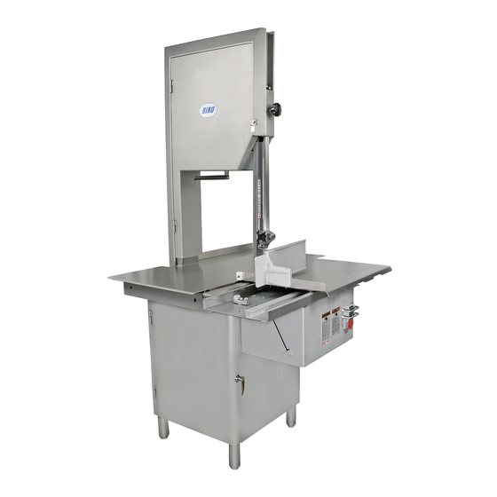
- Page 1 MODEL 44SSFH FIXED HEAD POWER MEAT SAW OPERATING AND SERVICE MANUAL STARTING WITH SERIAL NO. 9105 IMPORTANT NOTICE This Manual contains important safety instructions which must be strictly followed when using this equipment. MD44SSFH 371-5-18-3 B...
-
Page 2: Table Of Contents
TABLE OF CONTENTS: PAGE NOTICE TO OWNERS AND OPERATORS ..........SAFETY TIPS . -
Page 3: Notice To Owners And Operators
Warnings related to possible damage are indicated by: BIRO also has provided a wall chart to be posted near the equipment. If any warning label, wall chart, or Manual becomes misplaced, damaged, or illegible, please contact your nearest Distributor or BIRO directly for a replacement. -
Page 4: Safety Tips
BEFORE Removing Shrouds, Removable Guards, Covers, Doors, Fences or Panels for Cleaning, Servicing or Any Other Reason. NEVER Leave Machine Unattended While Saw is Running. PROMPTLY REPLACE Any Worn or Illegible Warning Labels. USE ONLY BIRO Parts and Accessories Properly Installed. -
Page 5: Installation
1. Read this Manual thoroughly before installation and operation. Do not proceed with installation and operation if you have any questions or do not understand anything in this Manual. Contact your local Distributor, or BIRO first. 2. Install machine on a level, solid, non-skid surface in a well-lighted work area away from children and visitors. - Page 6 5. The drive belt is packed loose in machine to prevent deformation, and must be installed on pulleys at time of wiring motor. 6. The BIRO Manufacturing Company is not responsible for permanent wiring, connection or installations. NOTE TO OWNER AND ELECTRICIAN: IF THIS MACHINE IS...
- Page 7 15. Check placement of all warning labels, wall chart and Manual. Machine is ready for trained operators to process product. 16. Contact your local Distributor or BIRO directly if you have any questions or problems with the installation or operation of this machine.
-
Page 8: Warning Label Locations On Machine
WARNING LABEL LOCATIONS ON MACHINE ATTACH TO CHANNEL BRACKET ATTACH ON HEAD STRUCTURE NEXT TO SWITCH BUTTONS MODEL/SERIAL NUMBER TAG P/N 720 BLADE TENSION ADJUSTMENT DECAL LOCATED INSIDE HEADDOOR P/N 708 “DANGER EXPOSED BLADE” DECAL ATTACHED TO SAW GUARD ON SAW GUIDE BAR NOT TO SCALE... -
Page 9: Wall Chart (Part No. 671)
ITEM NUMBER 671 WALL CHART “BAND SAW SAFETY GUIDELINES” ATTACH TO WALL IN VICINITY OF MACHINE IN EASY VIEW OF OPERATOR... -
Page 10: Operation
OPERATION SHARP MOVING BAND TYPE SAW BLADE TO AVOID SERIOUS PERSONAL INJURY ONLY Properly Trained Personnel Should Use This Equipment. ALWAYS Read Operating and Parts Manual BEFORE Operating. ALWAYS Keep Hands Clear of Band Type Saw Blade and Other Moving Parts. DO NOT Tamper With, Bypass, Alter, or Modify this Equipment in Any Way or Form. -
Page 11: To Process Product
6. ALWAYS use the Safety End Cut Pusher Plate for smaller products or the last cuts of product. “C” The pusher plate is supplied as standard on all Biro power saws. 7. When finished cutting, push stop button. Perform lockout/tag out procedure. -
Page 12: General
NEVER Bypass, Alter, or Modify This Equipment in Any Way From Its Original Condition. PROMPTLY REPLACE Any Worn or Illegible Warning Labels. USE ONLY GENUINE BIRO Parts and Accessories Properly Installed. A. GENERAL 1. Machine should be generally inspected every time it is cleaned (at least daily) to ensure that it is in good condition and has not been damaged or tampered with. -
Page 13: Cleaning
Components. ALWAYS Thoroughly Clean Equipment at Least Daily. CLEANING THE BIRO POWER SAW: Disconnect electrical power to the machine before cleaning. Parts to be removed have been made accessible and can be removed without tools. Notice in the drawing below that all parts are numbered. Each part should be removed for cleaning in the numbered sequence shown. - Page 16 MODEL 44 FIXED HEAD BLADE TENSION ASSEMBLY AS18006E HHS058S 55138 S18005E S18335XE LW15S S18253 HHS0481S LW30S HN40S HHS124S 55170 A16112 55312 0909 16112 55314 55313 112-212 55184 A18003U HHS060S 55172 LW30S 55171 55178 360A1 14554 CB137S HHS048S AN15S 55173 Item Number Description Item Number Description...
- Page 17 A18003U335E OR A18003U335E-DF (SERIAL NO. 9501 ON) UPPER WHEEL ASSEMBLY WITH HINGE PLATE A18003U OR A18003U-DF UPPER WHEEL ASSEMBLY WITHOUT HINGE PLATE A18247 UPPER SHAFT BEARING ASSEMBLY WITHOUT WHEEL S18335XE 18003U 18248 S18252 18230DL 247A 18247 HHS010S HN40S A18227 BEARING CUP/ CONE ASSEMBLY A18227 BEARING CUP/...
- Page 18 AS16132 AS415D REAR STEEL CLEANER ASSEMBLY, SS STATIONARY BAR ASSEMBLY, SS Item No. Description Item No. Description AS130 Saw cleaner assembly, SS AS415D Stationary bar assembly, SS AS16132 Rear saw blade cleaner assembly, SS HHS025S Hex head screw, -20 x 1/2, SS ¼...
- Page 19 AS290 CLEANING UNIT ASSEMBLY, SS Item No. Description A295 Wheel cleaner assembly AS16Z Guide bracket saw cleaner assembly, SS AS290 Cleaning unit assembly, SS FHS20S Flat head screw, 10-32 x ½” SS FW06S Flat washer, ¼”, SS HHS003S Hex head screw, 8-32 x ¼”, SS HHS004S Hex head screw, 8-32 x ⅜”, SS HHS009S...
- Page 20 A181155EZ MEAT CARRIAGE ASSEMBLY, EZ FLOW Description Item No. Description Item No. S181155AEZ Thumb guard assembly Carriage bearing angle plate, (NSS) A175S S18155EZ-1 Meat carriage assembly, EZ Flow Carriage top w/ weld studs A181155EZ 16155-13 Acorn nut, -20, SS Carriage stop angle, SS AN15S ¼...
-
Page 21: Operator's Notes
AS1120EZ CHANNEL ASSEMBLY, EZ FLOW Item No. Description A16200 Channel stop assembly, movable A16220-1 Channel stop assembly, fixed AS1120EZ Channel assembly, EZ Flow FW08S Flat washer, ⅜ FW15S Flat washer, ½ HHS055S Hex head screw, -18 x , SS ¾ HHS075S Hex head screw, -16 x 1... -
Page 22: Switch Assemblies And Service Parts
A609AAW-18 SWITCH ASSEMBLY 241WH 241BL 224 & 259 340 (3) 224 & 259 HN10S (3) 226-28 HHS010S (3) LW20S HHS070S 16296-2 609AAW HN20S (2) LW15S (2) A16226A H462A H462-2 Item No. Description A16226A Green/red switch button assembly w/ springs A609AAW-18 Switch assembly, 1 &... -
Page 23: Wiring Diagrams
609AAW WIRING SCHEMATIC... - Page 24 WATERTIGHT MAGNETIC SWITCH ASSEMBLIES (AEG) INCLUDES MOUNTING BRACKET AND WIRES Item No. Description Item No. Description A22618EE-522 A22618EE-540 BAEG/PC-PB/C14 3HP, 208-220-50/60-3 BAEG/MS-PB/C18 5HP, 208/230-50/60-3 A22618EE-534 A22618EE-544 BAEG/MS-PB/05-E8 5HP, 440/460-60-3 BAEG/MS-PB/05-E6.3 3HP, 440/460-60-3 A22618EE-536 BAEG/MS-PB/05-D8 3HP, 380/415-50-3 A22618EE-546 BAEG/MS-PB/05-D14 5HP, 380/415-50-3 A22618EE-538 A22618EE-548 BAEG/MS-PB/05-F8 BAEG/MS-PB/05-F4.7 3HP, 550/575-60-3...
- Page 25 MODEL 44SSFH SCHEMATIC USING 3PH AEG W.T. SWITCH MODEL 44SSFH SCHEMATIC USING 3PH AEG W.T. SWITCH FOR 220/380/440 VOLTS, THREE PHASE, 60 CYCLE BALDOR MOTOR FOR 220/380/440 VOLTS, THREE PHASE, 60 CYCLE BALDOR MOTOR...
-
Page 26: Operator's Notes
OPERATOR’S NOTES... -
Page 27: Wearable Saw Parts List
Item No. 16159 SAW CLEANER BRACKET STEEL BLADE CLEANER CARRIAGE BEARING — EXCEPT WHERE NOTED OTHERWISE — WEARABLE SAW PARTS THAT WILL FIT BIRO POWER CUTTERS CONTACT YOUR NEAREST BIRO AUTHORIZED DISTRIBUTOR — EXCEPT WHERE NOTED OTHERWISE — CARRIAGE BEARING ALL SAWS... -
Page 28: Parts List / Ordering
MODEL 44SSFH PART NUMBERS AND DESCRIPTIONS PROVIDE MODEL AND SERIAL NO. WHEN ORDERING PARTS MOTOR SECTION Item No. Description Item No. Description S229 Wheel cleaner arm spring, SS M79-G56111-U Motor, 3HP, 208/220/440-50/60-3 open S235 Taper pin, #4 x ¾, SS... -
Page 29: Parts Assemblies List / Ordering
MODEL 44SSFH PART NUMBERS AND DESCRIPTIONS (Cont.) Item No. Item No. Description Description Finger lift bracket Motor shim, ” 211A-291Q 324A Finger lift fastener knob, 4-point Motor shim, ⅛” 212CP Cotter pin, ⅛ x ¾, SS 360A1 Lower bearing housing angle grease fitting... -
Page 30: Operator's Notes
OPERATOR’S NOTES... -
Page 31: Operator's Signature
OPERATOR’S SIGNATURE PAGE WARNING READ AND UNDERSTAND THIS ENTIRE MANUAL BEFORE SIGNING BELOW MY SIGNATURE ATTESTS THAT I HAVE COMPLETELY READ AND UNDERSTAND THIS MANUAL. I REALIZE THAT THIS MACHINE, IF OPERATED CARELESSLY, CAN CAUSE SERIOUS INJURY TO MYSELF AND OTHERS. NAME (PRINT) SIGNATURE SUPERVISOR’S... -
Page 32: Limited Warranty
The warranty card must be returned to The BIRO Manufacturing Company for proper registra- tion. If no warranty card is returned to BIRO, the warranty period will begin from the date the machine was originally shipped from the factory.
Need help?
Do you have a question about the 44SSFH and is the answer not in the manual?
Questions and answers