
Related Manuals for BIRO 11


Summary of Contents for BIRO 11
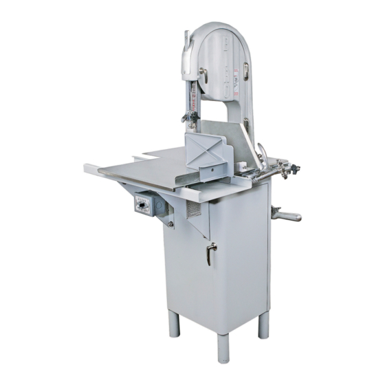
- Page 1 MODEL 11 POWER MEAT SAW OPERATING AND SERVICE MANUAL IMPORTANT NOTICE This Manual contains important safety instructions which must be strictly followed when using this equipment. PTCT 11 001-2-18-24 B...
-
Page 2: Table Of Contents
LUBRICATION ........ -
Page 3: Notice To Owners And Operators
Warnings related to possible damage are indicated by: BIRO also has provided a wall chart to be posted near the equipment. If any warning label, wall chart, or Manual becomes misplaced, damaged, or illegible, please contact your nearest Distributor or BIRO directly for a replacement. -
Page 4: Safety Tips
This Machine BEFORE Removing Shrouds, Removable Guards, Covers, Doors, Fences or Panels for Cleaning, Servicing or Any Other Reason. NEVER Leave Machine Unattended While the Saw is Running. PROMPTLY REPLACE Any Worn or Illegible Warning Labels. USE ONLY BIRO Parts and Accessories Properly Installed. -
Page 5: Wall Chart (Item No. 671)
ITEM NUMBER 671 WALL CHART “BAND SAW SAFETY GUIDELINES” ATTACH TO WALL IN VICINITY OF MACHINE IN EASY VIEW OF OPERATOR... -
Page 6: Installation
1. Read this Manual thoroughly before installation and operation. Do not proceed with installation and operation if you have any questions or do not understand anything in this Manual. Contact your local Distributor, or BIRO first. 2. Install machine on a level, solid, non-skid surface in a well-lighted work area away from children and visitors. - Page 7 The V-belt is packed loose in machine to prevent deformation, and must be installed on pulleys at time of wiring motor. f. The BIRO Manufacturing Company is not responsible for permanent wiring, connection or installations. NOTE TO OWNER AND ELECTRICIAN: IF THIS MACHINE IS NOT CORD...
-
Page 8: Warning Labels On Machine
11. Make sure saw guide bar with saw guard is in its lowest position. Close head and base doors. 12. Push the toggle switch to start or press start button and check for proper phasing of motor. Blade should be traveling down through the saw guide. -
Page 9: Operation
OPERATION SHARP MOVING BAND TYPE SAW BLADE TO AVOID SERIOUS PERSONAL INJURY ONLY Properly Trained Personnel Should Use This Equipment. ALWAYS Keep Hands Clear of Band Type Saw Blade and Other Moving Parts. NEVER Operate with Saw Guide Bar with Saw Guard in the Raised Position or the Saw Guard Removed from the Saw Guide Bar. - Page 10 6. ALWAYS use the Safety End Cut Pusher Plate (Item No. 256P) for smaller products or the last cuts of product. The pusher plate is supplied as standard on all BIRO power saws. 7. When finished cutting, push the toggle switch to stop or press stop button.
-
Page 11: Cleaning Procedure
• ALWAYS Thoroughly Clean Equipment at Least Daily. CLEANING THE BIRO POWER SAW: Disconnect electrical power to the machine before cleaning. Parts to be removed have been made accessible and can be removed without tools. Notice in the drawing below that all parts are numbered. Each part should be removed for cleaning in the numbered sequence shown. -
Page 12: Maintenance
PROMPTLY REPLACE Any Worn or Illegible Warning Labels. • USE ONLY GENUINE BIRO Parts and Accessories Properly Installed. A. GENERAL 1. Machine should be generally inspected every time it is cleaned (at least daily) to ensure that it is in good condition and has not been damaged or tampered with. -
Page 13: Lubrication
SAFETY ITEMS: Safety end cut pusher plate is with machine and accessible. All warning labels are present, properly affixed and legible. Model and Serial Number plate properly affixed and legible. Wall poster within operator’s view from machine. Manual accessible to operator. USE BIRO No. 374 GREASE FOR RE-GREASING B. LUBRICATION: SEE INSTRUCTIONS BELOW 1. -
Page 14: Parts Diagram
NOTE: ALWAYS REPORT MACHINE S71-0 10003U SERIAL NO. WHEN 10006 ORDERING PARTS 10005 A14U S10335X SEE #A116-13 SAW GUIDE BAR AND FINGER A112 LIFT ASSEMBLY S229 S244 S295 S325 211Q A14L 175-1-S S262 175-2-S S265 S270 10273 272-7-1 S264-1 264G 271AL TOGGLE SWITCH S10272... - Page 15 NOTE: ALWAYS REPORT MACHINE SERIAL NO. WHEN ORDERING PARTS SEE A116-13 10005 10301-2-B 653PC-E 211MS AS10275 602B 12662-AL 10302HT 256P 10212W 10155 212CP 10120 A260 A415D A220 SEE A196 A10163-1 10251AL SEE A19-1 SEE V-BELTS 221-XX NOT SHOWN: BASE PANEL DOOR SEE MOTOR PULLEYS LEFT SIDE: 10217PD 4-XXAL...
- Page 16 A10005 HEAD & DOOR ASSEMBLY S71-0 HHS050S (3) UPPER WHEEL LW15S (3) HINGE BRACKET ASSEMBLY SSS15S 10006 A14U HEAD DOOR HINGE ASSEMBLY - UPPER 14-0 14GP 14-0-U HHS035S (2) LW10S (2) S325 LW10S (2) HHS025S (2) 14GP-1 14-0 HHS010S 10308 10005 A112 375 (2)
- Page 17 A10003U335 (SERIAL NUMBER 7705 ON) UPPER WHEEL ASSEMBLY WITH HINGE PLATE A10003U (SERIAL NUMBER 7705 ON) UPPER WHEEL ASSEMBLY W/O HINGE PLATE S10335X A247-1 UPPER SHAFT BEARING ASSEMBLY W/O WHEEL 230DL A227 S252X 10003U A227 HHS010S HHS010S Hex head screw, 10-32 x ⅜, SS HN35S HN05S Hex nut, 8-32, SS...
- Page 18 Item No. Description Item No. Description A19-1 Ratchet assembly Ratchet trigger SS FW07S Flat washer, ⅜ SS S189 Ratchet arm stud SS HHS025S Hex head screw, ¼-20 x ½ SS Ratchet base SS HN15S Hex nut, ¼-20 SS S240 Ratchet trigger spring HN35S Hex nut, ⅜-16 SS 10-1...
- Page 19 A290CT CLEANING UNIT TOTAL ASSEMBLY A290CT A603604 LOWER BLADE CLEANING UNIT ASSEMBLY 603-1 BACK-UP GUIDE ASSEMBLY Item No. Description S604 A290CT Cleaning unit assembly w/ S604 HHS010S A295 Wheel cleaner assembly A295 A603604 Lower blade backup guide assembly WHEEL CLEANER AS130 Saw cleaner assembly, SS ASSEMBLY...
- Page 20 AS415D STATIONARY BAR ASSEMBLY, SS Item No. Description AS415D Stationary bar assembly, SS HHS025S Hex head screw, ¼-20 x ½ SS LW10S Lock washer, ¼ SS S268 Stationary bar headless screw S119A Saw guide in stationary bar, SS S415D Stationary bar, SS Nylon filler A196 TENSION SPRING ASSEMBLY Item No.
- Page 21 Item No. Description Item No. Description A10155 Meat carriage assembly complete 10155 Meat carriage top & angle A175S 155-1 Thumb guard assembly Meat carriage guide AN15S 155-3 Acorn nut, ¼-20, SS Meat carriage guide spacer, .025 FW06S Flat washer, ¼, SS 155-4 Meat carriage guide spacer, .040 HN15S...
-
Page 22: Switch Assemblies And Service Parts
TOGGLE SWITCHES NOTE SERIAL NO. REQUIRED Item No. Description A6808-G-12 Toggle switch assembly, 1 phase A7810-G-12 Toggle switch assembly, 3 phase HHS010S Hex head screw, 10-32 x ⅜, SS HHS040S Hex head screw, ¼-20 x ¼, SS HN10S Hex nut, 10-32, SS LW10S Lock washer, ¼, SS Conduit, ½, SS... -
Page 23: Wiring Diagrams
TOGGLE SWITCH (6808-G/7810-G) WIRING DIAGRAMS 110-115 VOLTS 220-230 VOLTS LINE 1 LINE 2 LINE 1 LINE 2 6808-G 6808-G TOGGLE TOGGLE SWITCH SWITCH MOTOR JUNCTION BOX MOTOR JUNCTION BOX 3 PHASE/ 230 VOLTS 3 PHASE/ 440 VOLTS 50/60 HZ ELECTRICAL 50/60 HZ ELECTRICAL SUPPLY SUPPLY... -
Page 24: Parts List/Ordering
MODEL 11 PART NUMBERS AND DESCRIPTIONS MODEL NO. AND SERIAL NO. REQUIRED WHEN ORDERING PARTS Description Item no. Description Item no. S71-0 AN15S Upper wheel hinge bracket Acorn nut, ¼-20, SS 10-1 Ratchet arm FW06S Flat washer, ¼ SS 10003 Lower saw wheel, 10”... -
Page 25: Parts Assemblies List /Ordering
MODEL 11 PART NUMBERS AND DESCRIPTIONS (Cont.) Item no. Description Item no. Description Upper shaft castellated lock nut washer Rubber bumper for stops 239-B31-2 Pipe leg, aluminum, 6” for AS239-B30-B Lower guide bracket stud 239-B32-AR Pipe leg cap for 239-B31-AR Motor shim, “... -
Page 26: Wearable Saw Parts
CARRIAGE BEA FACTURING ALL SAWS ALL SAWS CARRIAGE BEARING 11-22-33 1433-34-3334-44-55 ALL SAWS 11-22-33 WEARABLE SAW PARTS THAT WILL FIT BIRO POWER CUTTERS 1433-34-3334-44-55 ALL SAWS ALL SAWS 11-22-33 WEARABLE SAW PARTS THAT WILL FIT BIRO POWER CUTTERS 1433-34-3334-44-55 ce@birosaw.com MODELS... -
Page 27: Operator's Signature Page
OPERATOR’S SIGNATURE PAGE WARNING READ AND UNDERSTAND THIS ENTIRE MANUAL BEFORE SIGNING BELOW MY SIGNATURE ATTESTS THAT I HAVE COMPLETELY READ AND UNDERSTAND THIS MANUAL. I REALIZE THAT THIS MACHINE, IF OPERATED CARELESSLY, CAN CAUSE SERIOUS INJURY TO MYSELF AND OTHERS. NAME (PRINT) SIGNATURE SUPERVISOR’S... -
Page 28: Limited Warranty
The warranty card must be returned to The BIRO Manufacturing Company for proper registra- tion. If no warranty card is returned to BIRO, the warranty period will begin from the date the machine was originally shipped from the factory.
Need help?
Do you have a question about the 11 and is the answer not in the manual?
Questions and answers