Table of Contents
Advertisement
Quick Links
Advertisement
Table of Contents

Related Manuals for GIGA-BYTE TECHNOLOGY GA-F2A68HM-DS2H


Summary of Contents for GIGA-BYTE TECHNOLOGY GA-F2A68HM-DS2H
- Page 1 GA-F2A68HM-DS2H User's Manual Rev. 1001 12ME-F268D2H-1001R...
- Page 2 Nov. 5, 2014 Nov. 5, 2014 Copyright © 2014 GIGA-BYTE TECHNOLOGY CO., LTD. All rights reserved. The trademarks mentioned in this manual are legally registered to their respective owners. Disclaimer Information in this manual is protected by copyright laws and is the property of GIGABYTE.
-
Page 3: Table Of Contents
Table of Contents GA-F2A68HM-DS2H Motherboard Layout ..............4 GA-F2A68HM-DS2H Motherboard Block Diagram ............5 Chapter 1 Hardware Installation ..................6 Installation Precautions ..................6 ..................7 Installing the APU ..................... 9 Installing the Memory ..................9 Installing an Expansion Card ................. 10 ..........10 Back Panel Connectors .................. -
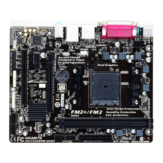
Page 4: Ga-F2A68Hm-Ds2H Motherboard Layout
GA-F2A68HM-DS2H Motherboard Layout KB_MS_USB ATX_12V Socket FM2+ CPU_FAN GA-F2A68HM-DS2H USB_LAN SATA3 Realtek ® GbE LAN AUDIO PCIEX16 PCIEX1 M_BIOS ® AMD A68H Super I/O B_BIOS CODEC CLR_CMOS SATA3 SYS_FAN2 F_AUDIO F_PANEL SPDIF_O SYS_FAN1 F_USB2 F_USB1 Box Contents GA-F2A68HM-DS2H motherboard Motherboard driver disk... -
Page 5: Ga-F2A68Hm-Ds2H Motherboard Block Diagram
GA-F2A68HM-DS2H Motherboard Block Diagram 1 PCI Express x16 PCIe CLK Dual Channel Memory AMD APU RJ45 Realtek ® D-Sub GbE LAN HDMI PCI Express Bus 1 x PCI Express x1 Dual BIOS 2 USB 3.0/2.0 PCI Bus 8 USB 2.0/1.1... -
Page 6: Chapter 1 Hardware Installation
Chapter 1 Hardware Installation Installation Precautions The motherboard contains numerous delicate electronic circuits and components which can become manual and follow these procedures: Prior to installation, make sure the chassis is suitable for the motherboard. warranty sticker provided by your dealer. These stickers are required for warranty validation. Always remove the AC power by unplugging the power cord from the power outlet before installing or removing the motherboard or other hardware components. - Page 7 FM2+ Socket: AMD A series processors AMD Athlon ™ series processors Chipset AMD A68H Memory 2 x DDR3 DIMM sockets supporting up to 64 GB of system memory * Due to a Windows 32-bit operating system limitation, when more than 4 GB of physical the physical memory installed.
- Page 8 Internal 1 x 24-pin ATX main power connector Connectors 1 x 8-pin ATX 12V power connector 4 x SATA 6Gb/s connectors 1 x APU fan header 2 x system fan headers 1 x front panel header 1 x front panel audio header 1 x S/PDIF Out header 2 x USB 2.0/1.1 headers 1 x Clear CMOS jumper...
-
Page 9: Installing The Apu
Installing the APU Read the following guidelines before you begin to install the APU: Make sure that the motherboard supports the APU. Always turn off the computer and unplug the power cord from the power outlet before installing the APU to prevent hardware damage. Locate the pin one of the APU. -
Page 10: Installing An Expansion Card
Installing an Expansion Card Read the following guidelines before you begin to install an expansion card: Make sure the motherboard supports the expansion card. Carefully read the manual that came with your expansion card. Always turn off the computer and unplug the power cord from the power outlet before installing an expansion card to prevent hardware damage. -
Page 11: Back Panel Connectors
Back Panel Connectors USB 2.0/1.1 Port PS/2 Keyboard and PS/2 Mouse Port Use this port to connect a PS/2 mouse or keyboard. Parallel Port Use the parallel port to connect devices such as a printer, scanner and etc. The parallel port is also called a printer port. -
Page 12: Internal Connectors
The line out jack. Use this audio jack for a headphone or 2-channel speaker. This jack can be used to Mic In Jack (Pink) The Mic in jack. Microphones must be connected to this jack. multi-channel audio feature through the audio driver. Internal Connectors ATX_12V F_USB1/F_USB2... - Page 13 1/2) ATX_12V/ATX (2x4 12V Power Connector and 2x12 Main Power Connector) With the use of the power connector, the power supply can supply enough stable power to all the components off and all devices are properly installed. The power connector possesses a foolproof design. Connect the power supply cable to the power connector in the correct orientation.
- Page 14 5) SATA3 0/1/2/3 (SATA 6Gb/s Connectors) The SATA connectors conform to SATA 6Gb/s standard and are compatible with SATA 3Gb/s and SATA 1.5Gb/s standard. Each SATA connector supports a single SATA device. The AMD Chipset supports RAID Pin No. Pin No. SATA3 drives.
- Page 15 sound cards. For example, some graphics cards may require you to use a S/PDIF digital audio cable for digital audio output from your motherboard to your graphics card if you wish to connect an HDMI display to the graphics card and have digital audio output from the HDMI display at the same time. For information about connecting the S/PDIF digital audio cable, carefully read the manual for your expansion card.
- Page 16 10) BAT (Battery) in the CMOS when the computer is turned off. Replace the battery when the battery voltage drops to a low level, or the CMOS values may not be accurate or may be lost. You may clear the CMOS values by removing the battery: 1.
-
Page 17: Chapter 2 Bios Setup
saving system parameters and loading operating system, etc. BIOS includes a BIOS Setup program that allows When the power is turned off, the battery on the motherboard supplies the necessary power to the CMOS to To access the BIOS Setup program, press the <Delete> key during the POST when the power is turned on. To upgrade the BIOS, use either the GIGABYTE Q-Flash or @BIOS utility. - Page 18 M.I.T. This section provides information on the BIOS version, CPU base clock, CPU frequency, memory frequency, Whether the system will work stably with the overclock/overvoltage settings you made is dependent on your overall and reduce the useful life of these components. This page is for advanced users only and we recommend you not to M.I.T.
- Page 19 Core Performance Boost Turbo Performance Boost Ratio Core Performance Boost Ratio Allows you alter the ratio for the CPB. The adjustable range is dependent on the CPU being installed. AMD Cool&Quiet function Enabled Lets the AMD Cool'n'Quiet driver dynamically adjust the CPU clock and VID to reduce Disabled Disables this function.
- Page 20 Advanced Memory Settings , System Memory Multiplier, Memory Frequency(MHz) The settings above are synchronous to those under the same items on the Advanced Frequency Settings menu. Memory Timing Mode Manual and Advanced Manual allows the Channel Interleaving, Rank Interleaving, and memory timing Channel Interleaving Enables or disables memory channel interleaving.
- Page 21 CPU/System Fan Fail Warning Allows the system to emit warning sound if the fan is not connected or fails. Check the fan condition or fan CPU Fan Speed Control Allows you to determine whether to enable the fan speed control function and adjust the fan speed. Normal Allows the fan to run at different speeds according to the CPU temperature.
-
Page 22: System Information
System Information This section provides information on your motherboard model and BIOS version. You can also select the default language used by the BIOS and manually set the system time. System Language Selects the default language used by the BIOS. System Date value. -
Page 23: Bios Features
Hard Drive BBS Priorities submenu will be presented here. string. Or if you want to install an operating system that supports GPT partitioning such as Windows 7 64-bit, select and devices that support Boot from LAN function, etc. Press <Enter> on this item to enter the submenu that presents the devices of the same type that are connected. - Page 24 Fast Boot Enables or disables Fast Boot to shorten the OS boot process. Ultra Fast provides the fastest bootup VGA Support Allows you to select which type of operating system to boot. Auto Enables legacy option ROM only. Fast Boot is set to Enabled or Ultra Fast. USB Support Disabled All USB devices are disabled before the OS boot process completes.
- Page 25 Allows you to select whether to enable the UEFI or Legacy option ROM for the PCI device controller other than the LAN, storage device, and graphics controllers. Legacy OpROM Enables legacy option ROM only. Disables or enables booting from the network to install a GPT format OS, such as installing the OS from Ipv4 PXE Support is enabled.
-
Page 26: Peripherals
Peripherals HD Audio Azalia Device If you wish to install a 3rd party add-in audio card instead of using the onboard audio, set this item to Disabled. Legacy USB Support XHCI Hand-off Determines whether to enable XHCI Hand-off feature for an operating system without XHCI Hand-off EHCI Hand-off Determines whether to enable EHCI Hand-off feature for an operating system without EHCI Hand-off Port 60/64 Emulation... - Page 27 Primary Video Device card or the onboard graphics. Integrated Graphics Enables or disables the onboard graphics function. Auto The BIOS will automatically enable or disable the onboard graphics depending on Disabled Disables the onboard graphics. Force Always activates the onboard graphics, whether or not a PCI Express card is installed.
-
Page 28: Power Management
Power Management Resume by Alarm If enabled, set the date and time as following: Wake up hour/minute/second: Set the time at which the system will be powered on automatically. Note: When using this function, avoid inadequate shutdown from the operating system or removal of the AC power, or the settings may not be effective. -
Page 29: Save & Exit
Set the password when is set to Password. Press <Enter> on this item and set a password with up to 5 characters and then press <Enter> to accept. To turn on the system, enter the password and press <Enter>. Note: To cancel the password, press <Enter> on this item. When prompted for the password, press <Enter> again without entering the password to clear the password settings. -
Page 30: Chapter 3 Appendix
Allows you to select a device to boot immediately. Press <Enter> on the device you select and select Yes Select File in HDD/USB/FDD If your system becomes unstable and you have loaded the BIOS default settings, you can use this function Select File in HDD/USB/FDD automatically created by the BIOS, such as reverting the BIOS settings to the last settings that worked... - Page 31 Steps: In BIOS Setup, go to and set Windows 8 Features to Windows 8 and CSM Support to Save the changes and exit BIOS Setup. Running the UEFI RAID Utility as shown in Figure 3. To run the UEFI RAID utility, enter the following commands. You can enter the commands at Shell or fsx: Checking Disk Information To see the hard drive information, enter the following commands and press <Enter>.
- Page 32 3. First, select a RAID mode and press <Enter>. The selections available depend on the number of the hard drives 4. Select a caching mode. Options include Read/Write, Read Only, and None. Then press <Enter> to proceed. return to the previous screen. Deleting an Array The Delete Array(s) menu option allows for deletion of disk array assignments.
-
Page 33: Drivers Installation
Refer to the following for installing the driver during the Windows setup process. Step 1: Restart your system to boot from the Windows XP setup disk and press <F6> as soon as you see the message "Press F6 if you need to install a 3rd party SCSI or RAID driver." A screen will then appear asking you to specify an additional SCSI adapter. -
Page 34: Regulatory Statements
Regulatory Statements This document must not be copied without our written permission, and the contents there of must not be imparted Contravention will be prosecuted. We believe that the information contained herein was accurate in all respects at the time of printing. GIGABYTE cannot, however, assume any responsibility for errors or omissions in this text. Also note that the information in this document is subject to change without notice and should not be construed as a commitment by GIGABYTE. - Page 35 This equipment has been tested and found to comply with the limits for a Class B digital device, pursuant to Part 15 of the FCC Rules. These limits are designed to provide reasonable protection against harmful interference in a residential installation. This equipment generates, uses, and can radiate radio frequency energy and, if not installed and used in accordance with the instructions, may cause harmful interference to radio communications.
-
Page 36: Contact Us
Contact Us Address: No.6, Bao Chiang Road, Hsin-Tien Dist., New Taipei City 231,Taiwan TEL: +886-2-8912-4000, FAX: +886-2-8912-4005 You may go to the GIGABYTE website, select your language in the language list on the top right corner of the website. GIGABYTE eSupport http://esupport.gigabyte.com - 36 -...
Need help?
Do you have a question about the GA-F2A68HM-DS2H and is the answer not in the manual?
Questions and answers