Table of Contents
Advertisement
Quick Links
Advertisement
Table of Contents

Subscribe to Our Youtube Channel
Related Manuals for GIGA-BYTE TECHNOLOGY GA-F2A55M-S1


Summary of Contents for GIGA-BYTE TECHNOLOGY GA-F2A55M-S1
- Page 1 GA-F2A55M-S1 User's Manual Rev. 1001...
- Page 2 Aug. 9, 2013 Aug. 9, 2013 Copyright © 2013 GIGA-BYTE TECHNOLOGY CO., LTD. All rights reserved. The trademarks mentioned in this manual are legally registered to their respective owners. Disclaimer Information in this manual is protected by copyright laws and is the property of GIGABYTE.
-
Page 3: Table Of Contents
Table of Contents GA-F2A55M-S1 Motherboard Layout ................4 GA-F2A55M-S1 Motherboard Block Diagram ..............5 Chapter 1 Hardware Installation ..................6 Installation Precautions ..................6 ..................7 Installing the APU ..................... 9 Installing the Memory ..................9 Installing an Expansion Card ................. 10 Back Panel Connectors .................. 10 Internal Connectors .................. -
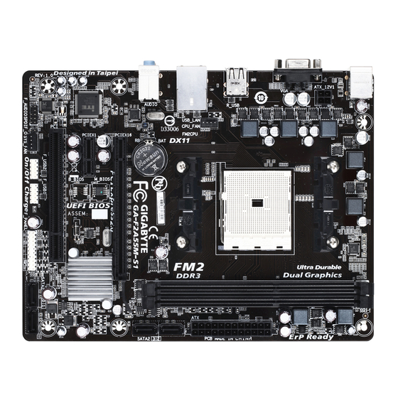
Page 4: Ga-F2A55M-S1 Motherboard Layout
GA-F2A55M-S1 Motherboard Layout KB_MS ATX_12V1 R_USB CPU_FAN USB_LAN AUDIO GA-F2A55M-S1 PCIEX16 Realtek ® SATA2 GbE LAN PCIEX1 ® M_BIOS AMD A55 Super I/O CODEC CLR_CMOS SPDIF_O SATA2 F_AUDIO SYS_FAN F_USB2 F_USB1 F_PANEL Box Contents GA-F2A55M-S1 motherboard Motherboard driver disk Two SATA cables... -
Page 5: Ga-F2A55M-S1 Motherboard Block Diagram
GA-F2A55M-S1 Motherboard Block Diagram 1 PCI Express x16 PCIe CLK AMD APU RJ45 DDR3 1866/1600/ ® Realtek GbE LAN Dual Channel Memory PCI Express Bus BIOS 1 PCI Express x1 4 SATA 3Gb/s AMD A55 8 USB 2.0/1.1 D-Sub PCI Bus ®... -
Page 6: Chapter 1 Hardware Installation
Chapter 1 Hardware Installation Installation Precautions The motherboard contains numerous delicate electronic circuits and components which can become manual and follow these procedures: Prior to installation, make sure the chassis is suitable for the motherboard. warranty sticker provided by your dealer. These stickers are required for warranty validation. Always remove the AC power by unplugging the power cord from the power outlet before installing or removing the motherboard or other hardware components. - Page 7 FM2 Socket: AMD A series processors ™ AMD Athlon series processors Chipset AMD A55 Memory 2 x 1.5V DDR3 DIMM sockets supporting up to 64 GB of system memory * Due to a Windows 32-bit operating system limitation, when more than 4 GB of physical the physical memory installed.
- Page 8 Internal 1 x S/PDIF Out header 2 x USB 2.0/1.1 headers Connectors 1 x Clear CMOS jumper Back Panel 1 x PS/2 keyboard port Connectors 1 x PS/2 mouse port 1 x D-Sub port 4 x USB 2.0/1.1 ports 1 x RJ-45 port I/O Controller ®...
-
Page 9: Installing The Apu
Installing the APU Read the following guidelines before you begin to install the APU: Make sure that the motherboard supports the APU. Always turn off the computer and unplug the power cord from the power outlet before installing the APU to prevent hardware damage. Locate the pin one of the APU. -
Page 10: Installing An Expansion Card
Installing an Expansion Card Read the following guidelines before you begin to install an expansion card: Make sure the motherboard supports the expansion card. Carefully read the manual that came with your expansion card. Always turn off the computer and unplug the power cord from the power outlet before installing an expansion card to prevent hardware damage. -
Page 11: Internal Connectors
Internal Connectors ATX_12V CLR_CMOS F_PANEL CPU_FAN F_AUDIO SYS_FAN SPDIF_O SATA2 0/1/2/3 F_USB1/F_USB2 Read the following guidelines before connecting external devices: First make sure your devices are compliant with the connectors you wish to connect. Before installing the devices, be sure to turn off the devices and your computer. Unplug the power cord from the power outlet to prevent damage to the devices. - Page 12 1/2) ATX_12V/ATX (2x2 12V Power Connector and 2x12 Main Power Connector) With the use of the power connector, the power supply can supply enough stable power to all the components off and all devices are properly installed. The power connector possesses a foolproof design. Connect the power supply cable to the power connector in the correct orientation.
- Page 13 5) SATA2 0/1/2/3 (SATA 3Gb/s Connectors) The SATA connectors conform to SATA 3Gb/s standard and are compatible with SATA 1.5Gb/s standard. Each SATA connector supports a single SATA device. The AMD A55 Chipset supports RAID 0, RAID 1, a RAID array. Pin No.
- Page 14 8) F_PANEL (Front Panel Header) Connect the power switch, reset switch, speaker, and system status indicator on the chassis to this header according to the pin assignments below. Note the positive and negative pins before connecting the cables. PLED/PWR_LED ( Power LED Power Switch Speaker...
-
Page 15: Chapter 2 Bios Setup
10) SPDIF_O (S/PDIF Out Header) sound cards. For example, some graphics cards may require you to use a S/PDIF digital audio cable for digital audio output from your motherboard to your graphics card if you wish to connect an HDMI display to the graphics card and have digital audio output from the HDMI display at the same time. -
Page 16: Startup Screen
Startup Screen The following startup Logo screen will appear when the computer boots. Function Keys On the main menu of the BIOS Setup program, press arrow keys to move among the items and press <Enter> to accept or enter a sub-menu. Or you can use your mouse to select the item you want. When the system is not stable as usual, select the Load Optimized Defaults item to set your system to its defaults. - Page 17 Whether the system will work stably with the overclock/overvoltage settings you made is dependent on your overall and reduce the useful life of these components. This page is for advanced users only and we recommend you not to M.I.T. Current Status This screen provides information on CPU/memory frequencies/parameters.
- Page 18 CPU Core Control Allows you to determine whether to manually enable/disable CPU cores. Automatic mode allows the BIOS (Note) enabled. (Note) System Memory Multiplier Allows you to set the system memory multiplier. Auto sets memory multiplier according to memory SPD Memory Frequency (MHz) This value is automatically adjusted according to the BCLK/PCIe Clock Control and System Memory Multiplier settings.
- Page 19 Advanced Voltage Settings This sub-menu allows you to set CPU, chipset and memory voltages. PC Health Status Reset Case Open Status Enabled Clears the record of previous chassis intrusion status and the Case Open show "No" at next boot. Case Open Displays the detection status of the chassis intrusion detection device attached to the motherboard CI clear the chassis intrusion status record, set Reset Case Open Status to Enabled, save the settings to the CMOS, and then restart your system.
-
Page 20: System Information
System Information This section provides information on your motherboard model and BIOS version. You can also select the default language used by the BIOS and manually set the system time. System Language Selects the default language used by the BIOS. System Date value. -
Page 21: Bios Features
BIOS Features Boot Option Priorities Boot Option #1 Boot Option #2 Hard Drive BBS Priorities submenu will be presented here. string. Or if you want to install an operating system that supports GPT partitioning such as Windows 7 64-bit, select Hard Drive/CD/DVD ROM Drive/Floppy Drive/Network Device BBS Priorities and devices that support Boot from LAN function, etc. - Page 22 CSM Support Never Disables UEFI CSM and supports UEFI BIOS boot process only. OS Type is set to Windows 8. Boot Mode Selection Allows you to select which type of operating system to boot. UEFI and Legacy Allows booting from operating systems that support legacy option ROM or UEFI Legacy Only Allows booting from operating systems that only support legacy Option ROM.
-
Page 23: Peripherals
Peripherals IOMMU OnChip SATA Channel OnChip SATA Type to AHCI mode. RAID Enables RAID for the SATA controller. Serial ATA features such as Native Command Queuing and hot plug. OnChip USB Controller HD Audio Azalia Device If you wish to install a 3rd party add-in audio card instead of using the onboard audio, set this item to Disabled. - Page 24 EHCI Hand-off Determines whether to enable EHCI Hand-off feature for an operating system without EHCI Hand-off Port 60/64 Emulation Enables or disables emulation of I/O ports 64h and 60h. This should be enabled for full legacy support for USB keyboards/mice in MS-DOS or in operating system that does not natively support USB devices. USB Storage Devices Displays a list of connected USB mass storage devices.
-
Page 25: Power Management
Power Management Resume by Alarm If enabled, set the date and time as following: Wake up hour/minute/second: Set the time at which the system will be powered on automatically. Note: When using this function, avoid inadequate shutdown from the operating system or removal of the AC power, or the settings may not be effective. -
Page 26: Save & Exit
Power On Password Set the password when Power On By Keyboard is set to Password. Press <Enter> on this item and set a password with up to 5 characters and then press <Enter> to accept. To turn on the system, enter the password and press <Enter>. Note: To cancel the password, press <Enter>... -
Page 27: Chapter 3 Appendix
Boot Override Allows you to select a device to boot immediately. Press <Enter> on the device you select and select Yes Select File in HDD/USB/FDD If your system becomes unstable and you have loaded the BIOS default settings, you can use this function Select File in HDD/USB/FDD automatically created by the BIOS, such as reverting the BIOS settings to the last settings that worked... - Page 28 This mode supports Windows 8 64-bit installation only. Create a RAID Array Step 1: In BIOS Setup, go to BIOS Features and set OS Type to Windows 8 and CSM Support to Never. Save the changes and exit BIOS Setup. Step 2: arrow key to select UEFI: Built-in EFI Shell.
-
Page 29: Drivers Installation
Steps: 1. Under the RAID Mode section, press the <SPACE> key to select RAID 0. 2. Set the Stripe Block 3. Under the Drives Assignments section, press the up or down arrow key to highlight a drive. 4. Press the <SPACE> key or <Y> to change the Assignment option to Y. This action adds the drive to the disk array. -
Page 30: Regulatory Statements
Regulatory Statements Regulatory Notices This document must not be copied without our written permission, and the contents there of must not be imparted Contravention will be prosecuted. We believe that the information contained herein was accurate in all respects at the time of printing. GIGABYTE cannot, however, assume any responsibility for errors or omissions in this text. Also note that the information in this document is subject to change without notice and should not be construed as a commitment by GIGABYTE. -
Page 31: Contact Us
Contact Us GIGA-BYTE TECHNOLOGY CO., LTD. Address: No.6, Bao Chiang Road, Hsin-Tien Dist., New Taipei City 231,Taiwan TEL: +886-2-8912-4000, FAX: +886-2-8912-4005 You may go to the GIGABYTE website, select your language in the language list on the top right corner of the website.
Need help?
Do you have a question about the GA-F2A55M-S1 and is the answer not in the manual?
Questions and answers