Table of Contents
Advertisement
Quick Links
Advertisement
Table of Contents

Related Manuals for Unipulse TM380


Summary of Contents for Unipulse TM380
- Page 1 TM380 TORQUE MONITOR OPERATION MANUAL 20MAY2021REV.1.02...
- Page 2 Installation, maintenance and inspection of the TM380 should be performed by personnel having technical knowledge of electricity. In order to have an TM380 Torque Monitor used safely, notes I would like you to surely follow divide into " " and "...
- Page 3 - Use greatly impacting human lives and assets, such as medical devices, transport devices entertainment devices, and safety devices. Warning on installation ● Do not disassemble, repair, or modify the TM380. Doing so may cause a fire or an electric shock. ● Do not install in the following environments.
- Page 4 ● For turning on/off the power, be sure to keep intervals of 5 seconds or more. ● After power-on, make sure to warm up the TM380 for at least 30 minutes or more before use. ● If the TM380 is not used by the specified method, its protective performance may be impaired.
- Page 5 Product Compliant to RoHS2 Directive Product Compliant to RoHS2 Directive Product Compliant to RoHS2 Directive The parts and attachments (including the instruction manual, packaging box, etc.) used for this unit are compliant with the RoHS2 Directive, restricting the use of hazardous substances with regard to adverse effects on the environment and human body.
-
Page 6: Table Of Contents
1-1. Main features of the TM380 ........ - Page 7 Contents Contents ■ Torque unit conversion table ......... 39 5 EXPLANATION OF INDICATED-VALUE-RELATED FUNCTIONS.
- Page 8 Contents Contents 7 EXPLANATION OF HOLD FUNCTIONS ......55 7-1. Hold functions of torque ..........55 ■...
- Page 9 ■ The injection of a power supply ........106 ■ Starting of the TM380 PC application software ......106 ■...
- Page 10 11-3. TM380 block diagram ........
- Page 11 Contents Contents M E M O...
-
Page 12: Outline
1-1. Main features of the TM380 ● The TM380 is a simple torque monitor that can easily be connected to our torque meter UTMⅢ and UTF series (UTMⅡ) with a dedicated cable (optionally available). ● In addition to torque, rotation speed and angle can also be displayed. -
Page 13: About Connectable Devices
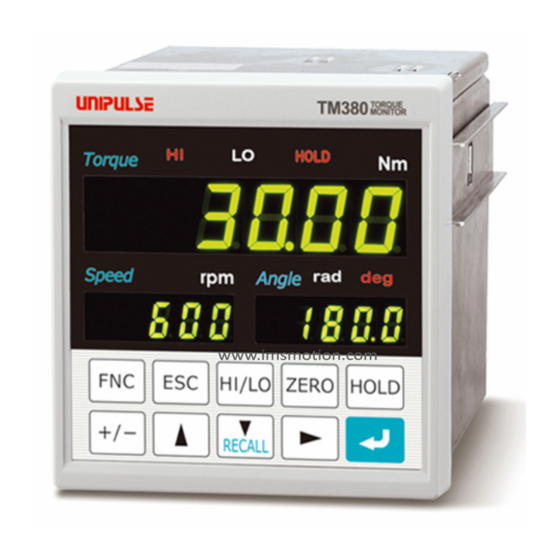
1 OUTLINE 1-3. About connectable devices Chapter UTM , UTF (UTM ) RS-485 (UTM , UTF) Voltage Display Encoder SI/F (Option) RS-232C (Option) D/A Converter BCD OUTPUT (Option) (Option) Valve, Recorder 1-4. Appearance description ■Front panel Main status display section Main numerical display section Sub unit display section (angle) Sub numerical display section Setting key pad... - Page 14 1 OUTLINE Main status display section Chapter The status with respect to torque is indicated. Lights when the indicated value is larger than the HI limit. Indicates that the external output "HI" is ON. Lights when the indicated value is smaller than the LO limit. Indicates that the external output "LO"...
- Page 15 1 OUTLINE Setting key pad Chapter These are keys for commanding settings and operations. - Use this key to go to a setting mode state. - Use this key to cancel setting/execution. - Use this key to go back from a setting mode state to an indication display state. - Use this key to take a shortcut from an indication value display state to HI/LO limit HI/LO setting.
-
Page 16: Rear Panel
1 OUTLINE ■Rear panel Chapter ■UTMⅢ (UTMⅡ) Options slot UTM Ⅲ/UTMⅡ connection connector DC power input Voltage output terminal block terminal Frame ground Signal input/output connector Rotary encoder connection connector UTMⅢ/UTMⅡ connection connector Connect a UTMⅢ/UTMⅡ with a dedicated cable. * For connection, see "■UTMⅢ/UTMⅡ connection" on page 11. Rotary encoder connection connector Connect the optional rotary encoder for UTMⅢ/ UTMⅡ... - Page 17 1 OUTLINE Options slot Chapter One option board can in stall in the option slot. - BCD parallel data output (BCO) - RS-232C interface (232) - D/A converter voltage output (3ch) (D3V) - D/A converter voltage output (DAV) - D/A converter current output (DAI) - USB interface (USB)
- Page 18 1 OUTLINE Frame ground Chapter Please ground the frame ground terminal to prevent failures due to static electricity. (The frame and the frame ground terminal are conducted.) It may be better to remove depending on the environment of the installation location. Options slot One option board can in stall in the option slot.
-
Page 19: Installation & Connection
2 INSTALLATION & CONNECTION INSTALLATION & CONNECTION The following are precautions related to connection. Chapter The precautions described here are important for safety. Make connections after properly understanding the description. WARNING ● Do not connect commercial power directly to the signal input/output terminals. ●... -
Page 20: Installation
2 INSTALLATION & CONNECTION 2-1. Installation To install the TM380 into a control panel, use the following procedure. Make a hole in the panel according to the 92mm Chapter panel-cut dimensions. – Panel-cut dimensions 92mm 0 – Panel thickness 1.6 to 3.2mm Remove the screws (two), and remove the guide rails from both sides. -
Page 21: Connection
- Be careful, as the voltage will drop depending on the diameters and lengths of the wires. Also, never input an AC power supply. Doing so may cause failure. - Since the TM380 has no power switch, install a breaker. - Be sure to ground the frame grounding terminal to prevent malfunctions arising from noise. -
Page 22: Utmⅲ/Utmⅱ Connection
2 INSTALLATION & CONNECTION ■UTMⅢ/UTMⅡ connection A UTMⅢ/UTMⅡ can easily be connected with the dedicated cable (Sold separately). Connect paying attention to the orientation of the connector. - UTMⅢ Chapter Torque Encoder - UTMⅡ Torque Encoder ●Pin assignments (torque) Cable color Function Signal name arrangement... -
Page 23: Utf Connection
The cable is nonpolar. Connect paying attention to the orientation of the connector. * Please prepare power supply for UTF. OUTPUT ●Pin assignments (OUTPUT) Pin arrangement Pin No. Cable color Signal at TM380 side Signal at UTF side SIG IN (±10V DC) SIG OUT (±10V DC) Black SIG GND SIG GND... -
Page 24: Voltage Output
2 INSTALLATION & CONNECTION ●Pin assignments (COM) Pin arrangement Pin No. Cable color Signal at TM380 side Signal at UTF side Orange RS-485 TX+ (B+) RS-485 RX+ (B+) Red dot Orange RS-485 TX- (A-) RS-485 RX- (A-) Black dot Chapter Gray... -
Page 25: External I/O Connection
COM2 terminal. Short-circuiting is effected by means of a contact (such as a relay or a switch) or a noncontact (such as a transistor or an open-collector TTL) Open → OFF TM380 Inside +12V Short → ON TTL Open Collector... -
Page 26: How To Assemble The Connector
Be aware that washers should be set to the M2×10 pan-head machine screws (two). ■SI/F interface connection Two-wire serial interface (SI/F) for connecting printers and external display from UNIPULSE. Connect from A11 and A12 of the external input/output connector. The interface is nonpolarized and up to three external devices can be connected. -
Page 27: Setting Mode Configuration
3 SETTING MODE CONFIGURATION SETTING MODE CONFIGURATION 3-1. Setting mode composition HI/LO HI limit LO limit Indicated value HI/LO limit setting mode display (P20, P50) Alarm HI limit Alarm LO limit * Torque/Rotation speed Chapter REC AL L Recording data History Up to 30 pieces (P77) HOLD... - Page 28 3 SETTING MODE CONFIGURATION Chapter HOLD HOLD HOLD HOLD Torque Torque Torque Torque Speed Angle rad deg Speed Angle rad deg Speed Angle rad deg Speed Angle rad deg F5 (Mode 5) F6 (Mode 6) F7 (Mode 7) F9 (Mode 9) Option setting RS-485 setting Encoder setting...
-
Page 29: Key Operation
3 SETTING MODE CONFIGURATION 3-2. Key operation ≪Setting procedure≫ From the indicated value display, Go back to the indicated value. "F1" of setting mode 1 is displayed on the SUB display (Rotation speed side). Speed Chapter Selecting a setting mode. Speed Go back to setting mode 1. - Page 30 3 SETTING MODE CONFIGURATION ≪Setting mode select state≫ 【Setting mode 1 (COP.HLD)】 【Setting mode 2 (SYS.1)】 【Setting mode 3 (SYS.2)】 HOLD HOLD HOLD Torque Torque Torque Speed Angle rad deg Speed Angle rad deg Speed Angle rad deg 【Setting mode 4 (CAL.)】 【Setting mode 5 (OPTION)】...
- Page 31 3 SETTING MODE CONFIGURATION ≪HI/LO limit setting mode function≫ By pressing on the indicated value display screen, you can enter a HI/LO limit setting HI/LO item select state. Press at the setting value you want to change, and you will go to a setting value input state.
-
Page 32: Calling A Setting Mode
3 SETTING MODE CONFIGURATION 3-3. Calling a setting mode Example) For changing the digital filter (torque) from "000" to "256" Press from an indicated value display HOLD Torque state. Speed Angle Chapter Go to a setting mode select state. HOLD Torque Press twice to make the mode number "3."... -
Page 33: Calibration Procedure
CALIBRATION PROCEDURE 4-1. How to perform calibration "Calibration" refers to an operation whereby matching between the TM380 and a sensor is obtained. The TM380 uses the two calibration methods as described below. ■Equivalent input calibration Calibration is performed without an actual load by entering the rated output value (V) and the capacity (to be indicated) of the sensor by the keys. -
Page 34: Procedure Of Equivalent Input Calibration And Calibration Protect (Torque)
4 CALIBRATION PROCEDURE 4-2. Procedure of equivalent input calibration and calibration protect (torque) The equivalent input calibration and the calibration protect uses the following procedure : Turn off the calibration protect that inhibits ① calibration. Calibration protect ② Set the voltage input according to the torque meter Voltage input select (UTMⅢ, UTF, UTMⅡ) used. - Page 35 4 CALIBRATION PROCEDURE ①Releasing the calibration protect Turn off the calibration protect that inhibits calibration. ≪Setting value≫ 0: OFF Enables rewriting of setting values. 1: ON Disables rewriting of setting values. ◇Calibration protect setting method Select setting mode 9. Speed Angle rad deg Press seven times.
- Page 36 4 CALIBRATION PROCEDURE ③Unit (torque) setting Set the unit for performing calibration. After this setting, make sure to perform calibration. ≪Setting value≫ 00: mNm 01: Ncm 02: Nm 03: kNm 04: kgm 05: kgcm 06: gcm ④Decimal place (torque) setting Set the decimal place for load-value-related display, setting items, etc. ≪Setting value≫...
- Page 37 4 CALIBRATION PROCEDURE ⑥Zero calibration Register the zero point with the sensor unloaded. Also, if there is any initial load, such as a jig, for measurements, the zero point can be registered with the initial load applied, but the signal input range needs to be considered as the initial load is subtracted from it.
- Page 38 4 CALIBRATION PROCEDURE ⑦a.Equivalent input calibration Check the specification of the sensor, and register the rated output value and the value you want to display at that time (rated capacity value). Input the rated output value and display value (rated capacity value) successively. Equivalent input calibration is not executed by simply inputting the rated output value.
- Page 39 4 CALIBRATION PROCEDURE Equivalent input calibration is executed. HOLD Torque A message as shown on the right-hand side is displayed. If equivalent input calibration is not executed normally, the alarm sounds. Speed Angle rad deg If equivalent input calibration is executed normally, HOLD Torque you will go back to the setting item select state.
- Page 40 4 CALIBRATION PROCEDURE ◇Actual load calibration setting method Select setting mode 4. Speed Angle rad deg Press three times. → Set "Actual load" of the sensor. HOLD Torque Press four times. ⇒ "Actual load calibration" is RECALL displayed. Speed Angle rad deg Enter a setting value input state with , and the highest digit blinks.
- Page 41 4 CALIBRATION PROCEDURE ⑧Digital offset (This step may be omitted if there is no change.) This function is to subtract a set value from the indicated value. This function is convenient when zero cannot be obtained with no load for some reason or for offsetting. When not using, set "0." (Displayed value) = (Actual indicated value)-(Setting value of digital offset) ≪Setting value≫...
-
Page 42: Rotation Speed Display Settings
4 CALIBRATION PROCEDURE ⑩Locking the calibration protect Turn on the calibration protect that inhibits calibration. ≪Setting value≫ 0: OFF Enables rewriting of setting values. 1: ON Disables rewriting of setting values. ◇Calibration protect setting method Select setting mode 9. Speed Angle rad deg Press seven times. -
Page 43: Low Speed Rotation Mode
4 CALIBRATION PROCEDURE ②Min. scale division (rotation speed) setting Set the minimum unit (scale interval, scale division) of the rotation speed. ≪Setting value≫ 0: 1 1: 2 2: 5 3: 10 During low speed rotation mode 0: 0.1 1: 0.2 2: 0.5 3: 1.0 ◇How to set the pulse rate and min. -
Page 44: Rotation Stop Settings For Rotation Speed
4 CALIBRATION PROCEDURE 4-4. Rotation stop settings for rotation speed ■Minimum input rotation speed (Only for UTMⅢ & UTMⅡ) Minimum input rotation speed that can be displayed is selectable. Max. detection time of UTF/60 pulses (F4-7) is 1sec, with min rotation speed at 1rpm. For encoder pulse (F4-7), min input rotation speed will be smallest in corresponding to max. - Page 45 4 CALIBRATION PROCEDURE Example) When decelerated suddenly with the setting of "4 times" 3000rpm New pulse is detected before T×4 time Display 1500rpm 1000rpm Sudden deceleration Pulse Final cycle T T×4 (Display held) ◇How to set the rotation stop mode and minimum input rotation speed Select setting mode 4.
-
Page 46: Settings/Operations Relevant To Calibration Of Encoder (Only When Encoder Is Used)
4 CALIBRATION PROCEDURE 4-5. Settings/operations relevant to calibration of encoder (Only when encoder is used) Calibration for the encoder uses the following procedure: ① Select whether to use encoder or not. Use of encoder Set the number of pulse input from the rotary encoder per a ②... - Page 47 4 CALIBRATION PROCEDURE ②Encoder pulse Set the number of pulse input from the rotary encoder per a rotation. ≪Setting value≫ 1 to 9999 ◇Encoder pulse setting method Select setting mode 7. Speed Angle rad deg Press six times. → Set "Encoder pulse." HOLD Torque Press...
- Page 48 4 CALIBRATION PROCEDURE ④Direction Set the rotation direction of torque meter. ≪Setting value≫ 0: NORMAL Select this option when using the torque meter counterclockwise viewing from the drive side. 1: REVERSE Select this option when using the torque meter clockwise viewing from the drive side.
-
Page 49: Unit Seal
4 CALIBRATION PROCEDURE ⑥Zero clear (This step may be omitted if there is no change.) Set the timing to reset the angle display to zero. When reached to the specified number of rotations, it goes back to zero. ≪Setting value≫ - When the unit (angle) is [0: deg] 1 to 55 (It becomes 1 to 5 when the minimum scale is 0.1 to 0.5.) - When the unit (angle) is [1: rad] 1 to 31... -
Page 50: Unit Conversion Table
4 CALIBRATION PROCEDURE 4-7. Unit conversion table Refer to the table for calibration of torque and unit setting. After the unit is changed, make sure to affix the attached unit seal. ■Torque unit conversion table kgcm 1.0197×10 1.0197×10 10.197 1.0197×10 0.10197 1.0197×10 0.10197 10.197... -
Page 51: Explanation Of Indicated-Value-Related Functions
5 EXPLANATION OF INDICATED- VALUE-RELATED FUNCTIONS EXPLANATION OF INDICATED- VALUE-RELATED FUNCTIONS 5-1. About each indicated value Torque Analog signal (±10V) from the UTMⅢ and UTF is displayed as torque. Rotation speed Pulse signal from the UTMⅢ, UTF and UTMⅡ is displayed as rotation speed. Angle Indicate pulse signal from UTF or optional rotary encoder of UTMⅢ... -
Page 52: Digital Hi-Pass Filter
5 EXPLANATION OF INDICATED- VALUE-RELATED FUNCTIONS Point You can only choose either digital low-pass filter or digital high-pass filter. If digital low-pass filter is selected at (3 to 1k [Hz]) , digital hi-pass filter (F3-8) will be set as 0 (PASS). 5-3. -
Page 53: Digital Filter
5 EXPLANATION OF INDICATED- VALUE-RELATED FUNCTIONS 5-4. Digital filter The digital filter is a function for reducing fluctuations of the indicated value by means of a moving average of data converted. With an increase in the number of filterings, the indicated value becomes more stable, but the response to inputs becomes slower. -
Page 54: Digital Zero
5 EXPLANATION OF INDICATED- VALUE-RELATED FUNCTIONS 5-6. Digital zero This function is to zero the indicated value. ■Digital zero / Digital zero reset by means of keys With respect to torque, digital zero can be executed. Digital zero reset can also be executed. Press on the normal measurement screen. -
Page 55: Zero Clear (Angle)
5 EXPLANATION OF INDICATED- VALUE-RELATED FUNCTIONS 5-7. Zero clear (Angle) This function changes the indicated value of angle to zero. ■Zero clear (angle) by means of keys With respect to angle, zero clear can be executed. Press ZERO twice on the normal measurement HOLD Torque screen. -
Page 56: Motion Detect Setting Method
5 EXPLANATION OF INDICATED- VALUE-RELATED FUNCTIONS Setting example Motion detect (time) 0.4 sec. Motion detect (range) Indicated value Motion detect time (0.4sec.) dn = 50msec. difference of the previous instruction value Time 50msec. Chapter When the condition of dn ≦ set count (010) continues for the set time (0.4 sec.) or more (d1 ≦... -
Page 57: Zero Tracking
5 EXPLANATION OF INDICATED- VALUE-RELATED FUNCTIONS 5-9. Zero tracking This function is to automatically track and correct gradual changes in the zero point due to drifts (phenomenon in which outputs fluctuate slowly due to temperature change or change with time), etc. ≪Setting value≫... -
Page 58: 5-10.Display Frequency
5 EXPLANATION OF INDICATED- VALUE-RELATED FUNCTIONS Point - When displacement of the zero point is within the set count of tracking and it continues more than the set time, it is automatically made zero by zero tracking function. - The time (tracking delay) is set in the range of 0.1 - 9.9 sec., and the band (tracking band) is set in the range of 001 to 999. -
Page 59: 5-11.Display On/Off
5 EXPLANATION OF INDICATED- VALUE-RELATED FUNCTIONS 5-11. Display ON/OFF The display of rotation speed and angle can be turned ON/OFF by this function. Torque is always displayed. Also, internal computation is not stopped. ■Display ON/OFF setting method Select setting mode 2. Speed Angle rad deg... - Page 60 5 EXPLANATION OF INDICATED- VALUE-RELATED FUNCTIONS Point After judgement of absolute value, select "1: Valid (marked)" if you want to know whether the current torque is positive or negative. The mark is displayed for current torque only, as it does not link with hold value. If reading is minus, "_"...
-
Page 61: Explanation Of Comparison Functions
6 EXPLANATION OF COMPARISON FUNCTIONS EXPLANATION OF COMPARISON FUNCTIONS 6-1. HI/LO limit comparison Set the HI/LO limit of torque and rotation speed. (Hold synchronized) ≪Setting value≫ - Torque HI limit/LO limit: -99999 to 99999 - Rotation speed HI limit/LO limit: 0 to 99999 (During low speed rotation mode: 0 to 9999.9) <HI/OK/LO output conditions>... -
Page 62: Hysteresis
6 EXPLANATION OF COMPARISON FUNCTIONS 6-2. Hysteresis This function is to allow a margin for timing at which HI/LO of the HI/LO limit comparison is turned off. Normally, HI is turned on when the indicated value exceeds the HI limit and is turned off when the indicated value falls below it. -
Page 63: Hysteresis Setting Method
6 EXPLANATION OF COMPARISON FUNCTIONS ■Hysteresis setting method Select setting mode1. Speed Angle rad deg Press once. Set "Hysteresis." HOLD Torque Press three times ⇒ "Hysteresis (Torque)" is RECALL displayed. Speed Angle rad deg Press four times for rotation speed ⇒ RECALL "Hysteresis (Rotation speed)"... -
Page 64: Comparison Timing
6 EXPLANATION OF COMPARISON FUNCTIONS 6-4. Comparison timing Set the operating conditions of HI/LO limit comparison (Torque). Select the conditions from the following. 0: All time HI/LO limit comparison is always performed. 1: Stable When stable, HI/LO limit comparison is performed. 2: Near zero OFF HI/LO limit comparison is performed when Near zero is off. -
Page 65: Timing Output
6 EXPLANATION OF COMPARISON FUNCTIONS Point B2 output can be either timing output or absolute value output. Refer to "5-12.Absolute value display select" on page 48 for absolute value display select. ■Timing output Outputs a signal in synchronization with current torque value. ON:... -
Page 66: Explanation Of Hold Functions
7 EXPLANATION OF HOLD FUNCTIONS EXPLANATION OF HOLD FUNCTIONS 7-1. Hold functions of torque The hold functions are to take out a specific point of torque for HI/LO limit comparison. Here, the operation of each hold will be described in detail. Hold mode Hold section 0: OFF... -
Page 67: Sample Hold
7 EXPLANATION OF HOLD FUNCTIONS ■Sample hold The start point of the specified section is held. The section is specified by the setting of "all section" or "external signal." (Example) All section sample hold t1: A delay time between the instant +... -
Page 68: Bottom Hold
7 EXPLANATION OF HOLD FUNCTIONS ■Bottom hold The maximum value in the negative direction (bottom value) of the specified section is held. The section is specified by the setting of "all section", "external signal", "external signal+time", or "level+time". (Example) All section Bottom hold t1: A delay time between the instant +... -
Page 69: Average Hold
7 EXPLANATION OF HOLD FUNCTIONS ■Average hold The average of the sampling values over the specified section is calculated and updated, and then held. The section is specified by the setting of "all section", "external signal", "external signal+time", or "level+time". (Example) Externally specified section average value hold t1: A delay time between the instant +... -
Page 70: Peak Hold (Angle)
7 EXPLANATION OF HOLD FUNCTIONS ■Peak hold (angle) In specified section, holds the max. value (peak value) of angle in positive direction. At angle hold point, torque and rotation speed will also be hold. The section is specified by the setting of "all section", "external signal", "external signal+time", or "level+time". -
Page 71: Peak Hold (Angle + Torque)
7 EXPLANATION OF HOLD FUNCTIONS ■Peak hold (angle + torque) In specified section, holds the max. value (peak value) of torque in positive direction and max. value (peak value) of angle in positive direction. The section is specified by the setting of "all section", "external signal", "external signal+time", or "level+time". -
Page 72: Setting Of Hold Section
7 EXPLANATION OF HOLD FUNCTIONS 7-3. Setting of hold section ■Hold section setting method Select setting mode 1. Speed Angle rad deg Press once. Set "Hold section." HOLD Torque Press seven times ⇒ "Hold function select " is RECALL displayed. Speed Angle rad deg Press... -
Page 73: External Signal
7 EXPLANATION OF HOLD FUNCTIONS ■External signal By this method, the hold detection section is specified by the SECTION signal. Detection starts with the SECTION signal ON, and ends with the SECTION signal OFF to perform each hold operation. The hold value is maintained until the hold reset signal is turned on. The hold is released by turning on the T/H signal as a reset signal. -
Page 74: External Signal + Time
7 EXPLANATION OF HOLD FUNCTIONS ■External signal + time By this method, the hold detection section is specified as a timer. Detection starts with the SECTION signal ON, and ends when the set time (detection time) has elapsed. The hold value is maintained until the hold reset signal is turned on. The hold is released by turning on the T/H signal as a reset signal. -
Page 75: Level + Time
7 EXPLANATION OF HOLD FUNCTIONS ■Level + time By this method, the hold detection section is specified as a timer. Hold is detected during the predetermined time (hold section time) from the point in time when the torque crosses the hold start level. -
Page 76: Auto Reset Function
7 EXPLANATION OF HOLD FUNCTIONS 7-4. Auto reset function It is factory-set that each hold is automatically reset at the start of the detection section, and therefore, simple control can be performed by one signal without releasing the hold. Example) Auto reset in externally specified section peak hold SECTION Upon turning-ON of the SECTION signal, Control can be performed without inputting the T/H... -
Page 77: Auto Reset Setting Method
7 EXPLANATION OF HOLD FUNCTIONS ■Auto reset setting method Select setting mode 1. Speed Angle rad deg Press once. Set "Auto reset." HOLD Torque Press seven times ⇒ "Hold function select " is RECALL displayed. Speed Angle rad deg Press , and the highest digit blinks. Press three times to make the digit of the auto reset blink. -
Page 78: B9 Off Detect Wait
7 EXPLANATION OF HOLD FUNCTIONS 7-6. B9 OFF detect wait In hold controlled by the T/H signal alone, detection/hold section is assured during the set waiting time. This is convenient for ignoring chattering parts. The timer functions so as to also ignore chattering when the OFF edge is detected. 《Setting value》... -
Page 79: Standard Interface
Outputs the alarm LO limit signal of rotation speed. Outputs the normal run signal. →"■About the RUN signal " on page 69 2-wire serial interface for connecting a UNIPULSE- →"■SI/F interface connection " on page 15 A11, A12 manufactured printer, external display, etc. -
Page 80: About Inputs
8 STANDARD INTERFACE ■About inputs Common for external input signals. →"■External I/O connection " on page 14 →"7.EXPLANATION OF HOLD B8, B9 Inputs the hold control signal. FUNCTIONS " on page 55 Inputs the zero clear (Angle) signal. →"5-7.Zero clear (Angle) " on page 44 Inputs the Digital Zero signal. - Page 81 8 STANDARD INTERFACE Point When stable value print is selected, be aware that automatic printing is not performed in the following case. - When motion detect is set in time: 0.0 sec, count: 000. Also, the indicated value is not held in the following case. - Hold mode: When any item other than none is selected.
-
Page 82: Communication Mode
8 STANDARD INTERFACE 8-3. RS-485 Usable when connecting to UTMⅢ & UTF (TM380 option). You can use RS-485 to change settings, digital zero, display torque and rotation speed of UTMⅢ & UTF (TM380option). Communication specifications Signal level Based on RS-485 Transmitting distance Approx. -
Page 83: Read Setting Values From Utm/Utf
Point E.g. To read filter setting, enter 1 & validate. After reading setting from UTM/UTF, Mode F6.2 of TM380 will return to 0. (Initial value) If restart power, Mode F6.3 - F6.5 will display 0. (Not value from UTM/UTF) Please note that setting read from UTM/UTF will not be kept. -
Page 84: Write Rotation Speed Filter To Utm/Utf
8 STANDARD INTERFACE ■Write rotation speed filter to UTM/UTF Write the following rotation speed filter to UTM/UTF. In addition, after reading rotation speed filter from UTM/UTF, the setting value from UTM/UTF will be shown at this item no. * Only applicable when "0: RS-485 command mode" "1: RS-485 display mode" is selected in communication mode. -
Page 85: Utm/Utf Assigned Action
8 STANDARD INTERFACE ■UTM/UTF assigned action UTM/UTF will execute assigned action. * Only applicable when "0: RS-485 command mode" "1: RS-485 display mode" is selected in communication mode. 《Setting value》 0: Cancel 1: Digital zero 2: Digital zero reset Select setting mode 6. Speed Angle rad deg... -
Page 86: Terminator
8 STANDARD INTERFACE ■RS-485 terminator Set termination resistor on receiving side of RS-485 at TM380. 《Setting value》 0: OFF 1: ON Select setting mode 6. Angle Speed rad deg Press → five times. Set "RS-485 terminator." HOLD Torque Press eight times. ⇒ "RS-485 terminator" is RECALL displayed. - Page 87 8 STANDARD INTERFACE Acquired data will be displayed in reference with setting of RS-485 dedicated rated capacity value. Rotation speed is displayed from acquired data. Signals input from the encoder are not digital data. Point Acquirable data from RS-485 is 300 times/sec.. Perform comparison / hold with acquired data.
-
Page 88: Record Function
9 RECORD FUNCTION RECORD FUNCTION 9-1. Record timing Each value (torque, rotation speed, and angle) is recorded according to a print command. Up to 30 pieces of the most recent data can be stored. If 30 pieces are exceeded, the oldest data in chronological order will be overwritten. -
Page 89: Record Data Clear
9 RECORD FUNCTION Point - Even while the history is displayed, when the record is updated, the record data are updated. In that case, the displayed data No. does not change but the record data alone change. - The record data are saved in F-RAM. 9-3. -
Page 90: Option Interface
10-1. BCD interface The BCD data output is an interface to extract the indicated value of the TM380 as BCD data. This interface is convenient to process controls, totals, records, etc., by connecting the TM380 to a computer, process controller, sequencer or the like. -
Page 91: Connector Pin Assignment
10 OPTION INTERFACE ●Input TM380 Transistor Inside Outside Approx.6mA Switch TTL open collector output (ON when IN is HI) Open Short CAUTION ● Do not apply external voltage to the signal input circuit. ● The external element is required to withstand Ic=10mA. -
Page 92: Output Data Select
10 OPTION INTERFACE ■Output data select 《Setting value》 0: Torque (hold synchronized) Torque synchronized with a hold is output. 1: Rotation speed The rotation speed is output. 2: Angle The angle is output. 3: Torque (hold not synchronized) Torque in real time is output. 4: External select Data selected by the data select input (A15, B15) is output. -
Page 93: Logic Switching
10 OPTION INTERFACE ■Logic switching Select the logic of the BCD data output signal. Make selection with B14. When COM and B14 are open: Negative logic When COM and B14 are short-circuited: Positive logic Read at least 2 cycles after inputting the logic switching. ■BCD data hold Updating of the BCD data output signal is stopped. -
Page 94: Bcd/Binary Select
10 OPTION INTERFACE ■BCD/binary select The output data selection can be changed to binary. 《Setting value》 0: BCD 1: Binary ◇BCD/binary setting method Select setting mode 5. Speed Angle rad deg Press → four times. Select "BCD/binary select." HOLD Torque Press three times. -
Page 95: 10-2.Rs-232C Interface
10-2. RS-232C interface The RS-232C is an interface to read the indicated value and status of the TM380 and to write parameters into the TM380. This interface is convenient to process controls, totals, records, etc., by connecting the TM380 to a computer, process controller, sequencer or the like. -
Page 96: Connection
2: Printed transmission mode When the indicated value is printed (a print command is output to the SI/F), the indicated value and status are sent from the TM380 to host. 3: Continuous transmission (hold not synchronized) mode This mode continuously transmits the indicated values and the status. -
Page 97: Communication Conditions
10 OPTION INTERFACE ◇Communication mode setting method Select setting mode 5. Speed Angle rad deg Press four times. → Set "Communication mode." HOLD Torque Press once. ⇒ "Communication mode" is RECALL displayed. Speed Angle rad deg Press , and present set value blinks. Input the setting value with RECALL (Initial value: 0) -
Page 98: Delimiter
10 OPTION INTERFACE ■Delimiter Set the delimiter for sending messages from the TM380. 《Setting value》 0: CR 1: CR+LF ◇Delimiter setting method Select setting mode 5. Speed Angle rad deg Press → four times. Set "Delimiter." HOLD Torque Press three times. ⇒ "Delimiter" is displayed. - Page 99 10 OPTION INTERFACE Reading the indicated value/status Header Function Protocol Main Host TM380 Delimiter Hold 0: OFF 1: ON Status1 Stable 0: OFF 1: ON (torque) Near zero 0: OFF 1: ON HI (torque) 0: OFF 1: ON OK (torque) 0: OFF 1: ON...
- Page 100 10 OPTION INTERFACE Reading the indicated value/status Header Function Protocol Main Host TM380 , , Torque (sign, 5-digit, decimal place) 11 12 14 15 16 17 18 Read all , (hold synchronized) Rotation speed (sign (fixation), 5-digit, decimal place) 19 20...
- Page 101 Header Function Protocol Main Host TM380 Command Setting value (sign, 5-digit, no decimal place) (For a setting value with a decimal place, simply write the numerical value excluding the decimal place.) * When the number of digits of the setting value is smaller than five, Various settings -...
- Page 102 10 OPTION INTERFACE 3. Send/receive [operation command] Movement directive Header Function Protocol Main Zero Host calibration TM380 Equivalent Host input TM380 calibration * Set the rated capacity value before sending an actual load calibration command. Digital zero Host TM380 Digital zero...
-
Page 103: Continuousness / Printed Transmission Mode
10 OPTION INTERFACE ■Continuousness / printed transmission mode Continuousness / printed transmission Header Function Protocol Main TM380 , , 13 14 16 17 18 19 20 21 22 24 25 26 27 ± , , Torque: 5-digit Rotation speed: 5-digit Sign Sign + + or-... -
Page 104: 10-3.D/A Converter Voltage Output (3Ch)
10 OPTION INTERFACE 10-3. D/A converter voltage output (3ch) This converter is used for obtaining analog outputs synchronized with torque, rotation speed and angle. The analog output ranges are -10 to +10V output. By using the D/A zero setting and D/A full scale setting functions, analog output can be obtained between zero (0V) and full scale (+10V) with respect to the predetermined digital value. -
Page 105: Connection
10 OPTION INTERFACE ■Connection A two-piece terminal block is used. Perform wiring with the plug pulled out from the option. Use of the operating tool included is recommended to facilitate wiring. Strip the casing 6.5 to 7.5mm on the cable to be 6.5 to 7.5mm connected. -
Page 106: Data Select
10 OPTION INTERFACE ■Data select When the output mode is "0: Data select", the analog output for torque, rotation speed and angle will be synchronized with the indicated value. The output data for each indicated value can be selected. 《Setting value》 0: Hold synchronized Outputs value synchronized with the indicated value. -
Page 107: Zero/Full Scale Setting
10 OPTION INTERFACE ■Zero/Full scale setting Zero scale 1 to 3 Set the indicated value to output 0V. Full scale 1 to 3 Set the indicated value to output 10V. The gain will be "full scale - zero scale". Outputs value within the range of ±gain with the set zero scale at the center. - Page 108 10 OPTION INTERFACE Set "Zero scale value 2 (rotation speed)," and "Full HOLD Torque scale value 2 (rotation speed)." ① Set "Zero scale value 2 (rotation speed)." Speed Angle rad deg Press once. ⇒ RECALL "Zero scale value 2 (rotation speed)" is displayed. Press , and the highest digit blinks.
-
Page 109: Angle Analog Output Select
10 OPTION INTERFACE ■Angle analog output select Can specify zero/full scale for angle analog output. 《Setting value》 0: Number of rotations Select number of rotations at encoder as standard. 1: Pulse rate Select pulse rate at encoder as standard. Can set in small scale. Example) For 360°... -
Page 110: Adjustment By Fixed Output
10 OPTION INTERFACE ■Adjustment by fixed output Make output adjustment on the adjustment screen appearing after selecting each fixed output by D/A output data select setting and pressing +/- Select the adjusting output channel with , and make fine adjustment of the output with while monitoring the output value. -
Page 111: 10-4.D/A Converter Output
A D/A converter is provided for obtaining analog output synchronized with the indicated value of the TM380. The analog output ranges are -10 to +10V output and 4 to 20mA constant-current output. By using the D/A zero setting and D/A full scale setting functions, analog output can be obtained between zero (0V, 4mA) and full scale (10V, 20mA) with respect to the predetermined digital value. -
Page 112: Output Data Select
10 OPTION INTERFACE CAUTION ● Cable can be from 24 to 14AWG (0.2 to 2.5mm ● It is not necessary to solder the cable wires or to fix a solderless terminal. ● If several cables to be inserted to the same hole, twist those cable wires together and insert. -
Page 113: Zero/Full Scale Setting
10 OPTION INTERFACE ■Zero/Full scale setting Zero scale Set the indicated value to output 0V for voltage output, and 4mA for current output. Full scale Set the indicated value to output 10V for voltage output, and 20mA for current output. 《Setting value》 Zero/Full scale value -99999 to 99999 (torque, rotation speed) * When output data select [2: Angle] is selected, setting range varies with the... -
Page 114: Angle Analog Output Select
10 OPTION INTERFACE ■Angle analog output select Can specify zero/full scale for angle analog output. 《Setting value》 0: Number of rotations Select number of rotations at encoder as standard. 1: Pulse rate Select pulse rate at encoder as standard. Can set in small scale. Example) For 360°... -
Page 115: Adjustment By Fixed Output
10 OPTION INTERFACE ■Adjustment by fixed output Make output adjustment on the adjustment screen appearing after selecting each fixed output by D/A output data select setting and pressing While monitoring the output value, make fine adjustment of the output with , and RECALL press to validate it, so that the adjusted value (%) is registered. -
Page 116: 10-5.Usb Interface
10-5. USB interface The USB is an interface to read the indicated value of the TM380 and to write parameters into the TM380. This interface is convenient to process controls, totals, records, etc., by connecting the TM380 to PC. Moreover, set values can be read and written by specific PC software, and also input signal can be shown in wave form. -
Page 117: Installation Of The Tm380 Pc Application Software
10 OPTION INTERFACE ■Installation of the TM380 PC application software When you use the TM380 PC application software, please download and install it from the Unipulse homepage. * https://www.unipulse.tokyo/en/product/tm380/ Download a compressed file from download page to a PC. Decompress the compressed file by the PC then start installer. -
Page 118: Communication Mode
This mode performs communication by a command from the host computer. In this mode, you can read out the indicated value, status, set values and write in set values. * Please be sure to use this setting in the case of use of the TM380 PC application software. -
Page 119: Communication Conditions
0: 9600 bps 1: 19200 bps 2: 38400 bps 3: 57600 bps 4: 115.2k bps 5: 230.4k bps ■Delimiter Set the delimiter for sending messages from the TM380. 《Setting value》 0: CR 1: CR+LF ◇Delimiter setting method Select setting mode 5. -
Page 120: Communication Format
10 OPTION INTERFACE ■Communication format The communication format is the same as an RS-232C interface (option). For details, see "■Communication format" on page 87. Point About the timing for continuous transmission Communication baud rate Continuous transmission interval times/sec. 230.4k bps times/sec. 115.2k bps times/sec. -
Page 121: 11Specifications
11 SPECIFICATIONS SPECIFICATIONS Chapter 11-1. Specifications ■Analog section Sensor input for torque (voltage input) Input resistance 1MΩ Signal input range -10 to +10V (UTMⅢ/UTF(option)) -5 to +5V (UTMⅡ/UTMV) Non-linearity Within 0.02%/F.S.±1digit Zero drift Within 0.2mV/℃ RTI Gain drift Within 0.01%/℃ Digital filter Selectable from 3 to 1k Hz and PASS. -
Page 122: Display Section
(Internal circuit power supply voltage: 12V) External output Open collector output circuit (sink type) for comparison output, etc. Rated voltage: 30V, driving current: 30mA or less ■Interface 2-wire serial interface for connecting a UNIPULSE-manufactured printer, external display, etc. Transmitting method Asynchronous Baud rate 600bps... -
Page 123: Options
11 SPECIFICATIONS RS-485 (Only for UTMⅢ/UTF) Signal level Based on RS-485 Chapter Transmitting distance Approx. 1 km Transmitting method Asynchronous, Full duplex Transmitting speed 230.4kbps Bit configuration Start bit: 1bit Character length: 8bit Stop bit: 1bit Parity: none Terminator: CR Code ASCII ■Options * Only one of the following options can be selected. -
Page 124: General Performance
11 SPECIFICATIONS D/A converter current output (DAI) Output range 4 to 20mA Chapter Load resistance 350Ω or less D/A conversion speed 8000 times per second Resolution 1/10000 Zero/span adjustment range ±10%F.S. Non-linearity ±0.05%F.S. Output data Selected by the setting of torque, rotation speed, or angle. RS-232C interface (232) Transmitting method Asynchronous... -
Page 125: 11-2.Dimensions
11 SPECIFICATIONS 11-2. Dimensions Chapter ■Standard equipment [Unit: mm] [Rear] [Top] [Front] [Side] ■Equipped with BCD parallel data output interface option [Unit: mm] [Rear] [Top] [Front] [Side]... -
Page 126: Equipped With Rs-232C Interface Option
11 SPECIFICATIONS ■Equipped with RS-232C interface option Chapter [Unit: mm] [Rear] [Top] [Front] [Side] ■Equipped with D/A converter (3ch) option [Unit: mm] [Rear] [Top] [Front] [Side]... -
Page 127: Equipped With D/A Converter Option
11 SPECIFICATIONS ■Equipped with D/A converter option Chapter [Unit: mm] [Rear (Voltage output)] [Rear (Current output)] [Top] [Front] [Side] ■Equipped with USB interface option [Unit: mm] [Rear] [Top] [Front] [Side]... -
Page 128: Tm380 Block Diagram
11 SPECIFICATIONS 11-3. TM380 block diagram Chapter +MONITOR -MONITOR SIG IN (±10V DC) Base (±5V DC) Buffer conversion voltage 24bit SIG GND PULSE IN+ PULSE IN- PWR+(+24V) DC24V PWR-(0V) PWR (+5V) Pulse Serial counter port PWR GND Watchdog 32bit 16KB F-RAM... -
Page 129: Supplements
12 SUPPLEMENTS SUPPLEMENTS 12-1. The list of initial setting value Chapter * Initial value Factory default value } * Protec Work protect ○: In accordance with "1. Setting protect" System protect ◎: in mode 9. Calibration protect ●: * NOVRAM Saved in NOVRAM ◎: No mark: Saved in F-RAM * Reference... - Page 130 12 SUPPLEMENTS ■Mode 1: Work setting (comparison/hold) Torque HOLD Item Initial Setting value name Setting value range Protect Reference value Chapter B2 output selection 0: Timing output 1: Absolute value output Comparison timing (Rotation speed) 0: All time Comparison function select 0010 1: Torque synchronized ○...
- Page 131 12 SUPPLEMENTS ■Mode 2: System setting (operation 1) Torque HOLD Item Initial Setting value name Setting value range Protect Reference value Motion detect (time) 0.0 to 9.9 ◎ ◎ Chapter Motion detect (range) 000 to 999 ◎ ◎ Zero tracking (time) 0.0 to 9.9 ◎...
- Page 132 12 SUPPLEMENTS ■Mode 4: Calibration setting Torque HOLD Item Initial Setting value name Setting value range Protect Reference value 0 2 2 Chapter Min. scale division (torque) 0: 1 1: 2 2: 5 3: 10 4: 20 5: 50 6: 100 Decimal place (torque) Calibration function select 1 0220...
- Page 133 12 SUPPLEMENTS ■Mode 5: Option setting (BCO option) Torque HOLD Item Initial Setting value name Setting value range Protect Reference value 0: Torque (hold synchronized) Chapter 1: Rotation speed 0: Torque Output data select 2: Angle ◎ ◎ (hold synchronized) 3: Torque (hold not synchronized) 4: External selection 0: 10 1: 25...
- Page 134 12 SUPPLEMENTS ■Mode 5: Option setting (D3V option) Torque HOLD Item Initial Setting value name Setting value range Protect Reference value 0 0 0 Chapter Data select 1 (torque) 0: Hold synchronized 1: Hold not synchronized Data select 2 (rotation speed) 0: Hold synchronized 1: Hold not synchronized Output data select...
- Page 135 12 SUPPLEMENTS ■Mode 5: Option setting (DAC (DAV/DAI) option) Torque HOLD Item Initial Setting value name Setting value range Protect Reference value 0 0 0 Chapter Output data select 0: Torque (hold synchronized) 1: Rotation speed 2: Angle 3: Torque Output data select 0000 P101 ◎...
- Page 136 12 SUPPLEMENTS ■Mode 6: RS-485 setting (UTMⅢ/UTF) HOLD Torque Item Initial Setting value name Setting value range Protect Reference value 0: RS-485 command mode 0: RS-485 RS-485 1: RS-485 display mode command ◎ ◎ Chapter communication mode 2: Iinvalid mode 0: Cancel 1: Filter setting UTM/UTF setting value read 0: Cancel...
- Page 137 12 SUPPLEMENTS ■Mode 7: Encoder setting HOLD Torque Item Initial Setting value name Setting value range Protect Reference value Use of encoder 0: Not use 1: Use 1: Use ● ◎ Chapter Encoder pulse 1 to 9999 3600 ● ◎ Unit (Angle) 0: deg 1: rad 0: deg...
-
Page 138: 12-2.Self-Check Function
This function is not to diagnose the analog circuit. Chapter ■Self-check method Turn off the power of the TM380. Turn on the power while pressing If "PASS" is displayed at the end, it is normal. -
Page 139: 12-3.Setting Protect
12 SUPPLEMENTS 12-3. Setting protect Each category of setting values can be locked to prevent rewriting. For each category, see the setting value list. 《Setting value》 Chapter 0: OFF Enables rewriting of setting values. 1: ON Disables rewriting of setting values. ■... -
Page 140: 12-4.Key Protect
12 SUPPLEMENTS 12-4. Key protect ZERO key and HOLD key operations are disabled to prevent misoperation. ≪Setting value≫ 0: OFF Enables key operations. Chapter 1: ON Disables key operations. ■Key protect setting method Select setting mode 9. Speed Angle rad deg Press seven times. -
Page 141: 12-5.Initialize
12 SUPPLEMENTS 12-5. Initialize Each category of setting values can be initialized. For each category, see the setting value list. ≪Setting value≫ Chapter (0: Undefined) 1: Work setting (Including record data) 2: System setting (Including setting protect and key protect) 3: Calibration setting After inputting the number of the setting value category you want to initialize, press validate it, and initialization is executed. -
Page 142: 12-7.Error/Message List
12 SUPPLEMENTS 12-7. Error/message list ■Main numerical display section Below the signal input range -LoAd -10V over (UTMⅢ/UTF) The input electric signal greatly exceeds the signal input Chapter -5V over (UTMⅡ) range. This also occurs when an excessive load is applied to the sensor or the input terminal is opened due to a break in Beyond the signal input range LoAd... -
Page 143: Sub Numerical Display Section
12 SUPPLEMENTS ■Sub numerical display section oFL2 The rotation speed exceeds the display range. Beyond +99999 Check the connection with the sensor. Beyond the alarm HI limit Rotation speed is at a faster or slower speed than expected. Chapter Confirm that rated rotation speed and rotation are not locked -ALA and so forth. - Page 144 GROSS area, NET area, and TARE area exist. Check that the areas abnormal. and setting correspond. Chapter SI/F Check to see if the SI/F print setting of the TM380 is correct. Check the setting. Automatic printing cannot be performed. Check to see if the printer side print setting is automatic printing.
-
Page 145: 12-9.Conformity With Ec Directives
CAUTION ● Since the TM380 is defined as open type (built-in equipment), be sure to use it as installed and fixed to a panel, etc. ● Use shielded cables (for encoder, USB, external input/output, UTM, and option(s)). -
Page 146: Connection Of A Lightning Surge Protector
12 SUPPLEMENTS ■Connection of a lightning surge protector Attach a lightning surge protector against lightning surge. EMC Directive EN61000-4-5 (Lightning Surge Immunity) is met by the TM380 body in combination with a lightning surge protector. Chapter Lightning surge protector <Connect> Lightning surge protector TM380 +...
Need help?
Do you have a question about the TM380 and is the answer not in the manual?
Questions and answers