Sign In
Upload
Manuals
Brands
Unipulse Manuals
Monitor
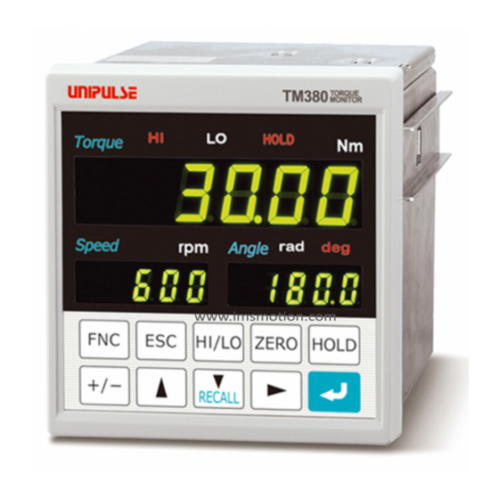
TM380
Unipulse TM380 Manuals
Manuals and User Guides for Unipulse TM380. We have
1
Unipulse TM380 manual available for free PDF download: Operation Manual
Unipulse TM380 Operation Manual (147 pages)
TORQUE MONITOR
Brand:
Unipulse
| Category:
Monitor
| Size: 4 MB
Table of Contents
Table of Contents
6
Outline
12
Main Features of the TM380
12
Contents of the Package
12
About Connectable Devices
13
Appearance Description
13
Front Panel
13
Rear Panel
16
Installation & Connection
19
Installation
20
Connection
21
DC Power Input Terminal Connection
21
UTMⅢ/UTMⅡ Connection
22
UTF Connection
23
Voltage Output
24
External I/O Connection
25
How to Assemble the Connector
26
F Interface Connection
26
Setting Mode Configuration
27
Setting Mode Composition
27
Key Operation
29
Calling a Setting Mode
32
Calibration Procedure
33
How to Perform Calibration
33
Equivalent Input Calibration
33
Actual Load Calibration
33
Procedure of Equivalent Input Calibration and Calibration Protect (Torque)
34
Rotation Speed Display Settings
42
Low Speed Rotation Mode
43
Rotation Stop Settings for Rotation Speed
44
Minimum Input Rotation Speed (Only for UTMⅢ & UTMⅡ)
44
Rotation Stop Mode
44
Settings/Operations Relevant to Calibration of Encoder (Only When Encoder Is Used)
46
Unit Seal
49
Unit Conversion Table
50
Torque Unit Conversion Table
50
Explanation of Indicated-Value-Related Functions
51
About each Indicated Value
51
Digital Low-Pass Filter
51
Digital Low-Pass Filter (Torque) Setting Method
51
Digital Hi-Pass Filter
52
Digital Hi-Pass Filter (Torque) Setting Method
52
Digital Filter
53
Digital Filter (Torque) Setting Method
53
Dead Band
53
Dead Band Setting Method
53
Digital Zero
54
Digital Zero / Digital Zero Reset by Means of Keys
54
Digital Zero by Means of the External Signal "D/Z Input
54
Zero Clear (Angle)
55
Zero Clear (Angle) by Means of Keys
55
Zero Clear (Angle) by Means of the External Signal "Zero Clear (Angle) Input
55
Motion Detect
55
Motion Detect Setting Method
56
Zero Tracking
57
Zero Tracking Setting Method
57
5-10.Display Frequency
58
Display Frequency Setting Method
58
5-11.Display ON/OFF
59
Display ON/OFF Setting Method
59
5-12.Absolute Value Display Select
59
Absolute Value Display Select Setting Method
59
Explanation of Comparison Functions
61
HI/LO Limit Comparison
61
HI/LO Limit Setting Method
61
Alarm HI and lo Limits Setting Method
61
Hysteresis
62
Hysteresis Setting Method
63
Near Zero
63
Near Zero Setting Method
63
Comparison Timing
64
Comparison Timing (Torque), Comparison Timing (Rotation Speed)
64
B2 Output Selection Setting Method
64
Timing Output
65
Explanation of Hold Functions
66
Hold Functions of Torque
66
Flow of Hold Measurement
66
Setting of Hold Mode
66
Hold Mode Setting Method
66
Sample Hold
67
Peak Hold
67
Bottom Hold
68
Peak-To-Peak (P-P) Hold
68
Average Hold
69
Peak Hold (Angle)
70
Peak Hold (Angle + Torque)
71
Setting of Hold Section
72
Hold Section Setting Method
72
All Section
72
External Signal
73
External Signal + Time
74
Level + Time
75
Auto Reset Function
76
Auto Reset Setting Method
77
B8 off Detect Wait
77
B9 off Detect Wait
78
Standard Interface
79
External I/O
79
Connector Pin Assignment
79
About Outputs
79
About Inputs
80
About the RUN Signal
80
F (Serial Interface)
80
F Indicated Value Format
80
F Print
80
Communication Mode
82
Read Setting Values from UTM/UTF
83
Write Filter Setting to UTM/UTF
83
Write Rotation Speed Filter to UTM/UTF
84
Write Minimum Rotation Speed Display to UTM/UTF
84
UTM/UTF Assigned Action
85
Dedicated Rated Capacity Value
85
Terminator
86
About RS-485 Command Mode & RS-485 Display Mode
86
Record Function
88
Record Timing
88
History
88
Record Data Clear
89
Clear by Means of Keys
89
Clear by Means of the External Signal "CLEAR Input
89
Clear by Means of Communication (232/USB Option)
89
Option Interface
90
10-1.BCD Interface
90
Connection
90
Connector Pin Assignment
91
Output Data Select
92
Signal Timing
92
Logic Switching
93
BCD Data Hold
93
Output Rate
93
Bcd/Binary Select
94
Pin Assignment at Binary
94
10-2.RS-232C Interface
95
Communication Specifications
95
Connector Pin Assignment
95
Connection
96
Communication Mode
96
Communication Conditions
97
Delimiter
98
Communication Format
98
Continuousness / Printed Transmission Mode
103
10-3.D/A Converter Voltage Output (3Ch)
104
Connector Pin Assignment
104
Connection
105
Output Mode
105
Data Select
106
Zero/Full Scale Setting
107
Angle Analog Output Select
109
Adjustment by Fixed Output
110
10-4.D/A Converter Output
111
Connection
111
Output Data Select
112
Zero/Full Scale Setting
113
Angle Analog Output Select
114
Adjustment by Fixed Output
115
10-5.USB Interface
116
Communication Specifications
116
PC Hardware Requirement
116
Installation of a USB Driver
116
Connection of USB
116
The Check of a Virtual COM Port
116
Installation of the TM380 PC Application Software
117
The Injection of a Power Supply
117
Starting of the TM380 PC Application Software
117
Specification of a COM Port
117
The Check of a Indicating Value
117
Communication Mode
118
Communication Conditions
119
Delimiter
119
Communication Format
120
11Specifications
121
Analog Section
121
Display Section
122
Setting Section
122
External Input/Output Section
122
Interface
122
Options
123
General Performance
124
Attachment
124
11-2.Dimensions
125
Standard Equipment
125
Equipped with BCD Parallel Data Output Interface Option
125
Equipped with RS-232C Interface Option
126
Equipped with D/A Converter (3Ch) Option
126
Equipped with D/A Converter Option
127
Equipped with USB Interface Option
127
TM380 Block Diagram
128
Supplements
129
12-1.The List of Initial Setting Value
129
12-2.Self-Check Function
138
Self-Check Method
138
12-3.Setting Protect
139
Setting Protect Setting Method
139
12-4.Key Protect
140
Key Protect Setting Method
140
12-5.Initialize
141
Initialize Setting Method
141
12-6.Password
141
12-7.Error/Message List
142
Main Numerical Display Section
142
Sub Numerical Display Section
143
12-8.Troubleshooting
143
12-9.Conformity with EC Directives
145
Attachment of the Ferrite Core
145
Connection of a Lightning Surge Protector
146
Advertisement
Advertisement
Related Products
Unipulse TM201
Unipulse TM700
Unipulse TM200
Unipulse TM500
Unipulse TM400
Unipulse LD557A
Unipulse Categories
Measuring Instruments
Touch Panel
Controller
Monitor
Accessories
More Unipulse Manuals
Login
Sign In
OR
Sign in with Facebook
Sign in with Google
Upload manual
Upload from disk
Upload from URL