Table of Contents
Advertisement
Quick Links
Advertisement
Table of Contents

Subscribe to Our Youtube Channel
Related Manuals for Unipulse LD557A


Summary of Contents for Unipulse LD557A
-
Page 2: Safety Precautions
Installation, maintenance and inspection of the LD557A should be performed by personnel having technical knowledge of electricity. In order to have an LD557A Weighing Controller used safely, notes I would like you to surely follow divide into " " and "... - Page 3 Warning on installation ● Do not disassemble, repair, or modify the LD557A. Doing so may cause a fire or an electric shock. ● Do not install in the following environments. - Places containing corrosive gas or flammable gas.
- Page 4 ● Make sure to wire the power wire and signal wire from separate cord clips, and use cabtyre cables in the applicable wire range. If the LD557A is not used by specified methods, its waterproof performance may be impaired.(Applicable wire:φ7~9mm)...
-
Page 5: Table Of Contents
Contents Contents 1. Part names and functions ........1 2. -
Page 6: Part Names And Functions
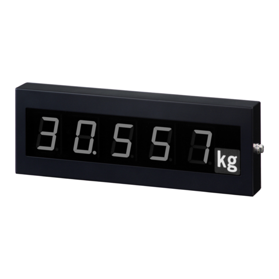
1.Part names and functions Part names and functions Wall mounting angle (left) Display section Unit indication Connector panel Wall mounting angle (right) Terminal block Display section Displays information received from an indicator, such as weight value. Unit indication Select an appropriate unit indication from the attached unit labels, and affix it in place. Connector panel You can access the internal terminal block and setting DIP switches by removing the six screws. -
Page 7: Terminal Block
3 and 4. (A short-circuit bar is factory-inserted between 3 and 4.) Setting DIP switches These are switches to set the operation of the LD557A. Make sure to always turn off No. 8 because it is intended for maintenance. -
Page 8: Connection
Do not remove other screws. Otherwise, the drip-proof and dust-proof performance will be affected. Set the DIP switches. Set the operation of the LD557A with the DIP switches as needed. Regarding how to make settings, see P.5 「3.Two-wire serial interface (SI/F)」 and see P.8 「4.20mA current loop interface (ACL)」for ACL connection. -
Page 9: Connection Of The Power Input Terminals
To hold the display value, short-circuit these two terminals. The - (minus) terminal serves as a COM terminal. In the drive circuit, a contact input (relay, switch, etc.) or non-contact input (transistor, TTL open collector output) can be used. LD557A Open +12V ← Inside Outside →... -
Page 10: Two-Wire Serial Interface (Si/F)
Tare weight display ← Inside Outside → The above example shows three LD557As connected to an F805A. Each LD557A can independently display data (gross weight, net weight, tare weight). * The maximum number of external devices connected depends on the indicator. -
Page 11: How To Make Settings
Caution Make sure to operate the DIP switches with the power off. The DIP switch settings are read only when the LD557A is powered on. If any setting is changed, turn off the power and then turn it on again. -
Page 12: About Display
3.Two-wire serial interface (SI/F) ■About display The display of the LD557A is updated each time a message is received from the indicator. The cycle of sending/receiving messages through the SI/F is normally about 3 times a second. However, while the HOLD signal is ON, the display content is maintained. -
Page 13: Ma Current Loop Interface (Acl)
This data format does not include data indicating the type of weight value (gross weight, net weight, or tare weight). In each case of receiving a message in this format, the LD557A displays the weight value irrespective of the display item setting. - Page 14 Message termination character string [CR][LF]or [CR] (*1) :The decimal point is positioned as desired, but if the position is undisplayable on the LD557A, the weight value display flashes. (*2) :The unit is not reflected on the display of the LD557A.
-
Page 15: Equivalent Circuit And Connection
4.20mA current loop interface (ACL) ■Equivalent circuit and connection In the case of only one LD557A +12V For one-to-one connection with an indicator, connect wiring materials to 1 Indicator ACL-1 - 2, and short-circuit 3 - 4 with the attached short-circuit bar because the... -
Page 16: How To Make Settings
Caution Make sure to operate the DIP switches with the power off. The DIP switch settings are read only when the LD557A is powered on. If any setting is changed, turn off the power and then turn it on again. -
Page 17: About Display
4.20mA current loop interface (ACL) ■About display Since the display of the LD557A is updated each time a message is received from the indicator, the display update cycle depends on the message sending interval of the indicator. However, while the HOLD signal is ON, the display content is maintained. -
Page 18: Self-Check
Turn on the DIP switches from No. 1 to No. 7, and turn on the power to enter the self-check mode. If the indicator connected through the SI/F carries out a self-check, the LD557A also enters the self-check mode. In this case, the LD557A goes back to its original condition after execution of steps 1 to 3 in the following table. -
Page 19: External View
6.Dimensions Dimensions [Unit : mm] ■With a suspension angle mounted [Unit : mm] ※ The suspension angle is an option. (OP1 : ANG)... - Page 20 6.Dimensions ■With a suspension angle mounted (at the bottom) [Unit : mm] ※ The suspension angle is an option. (OP1 : ANG) ■ With a hood mounted [Unit : mm] ※ The hood is an option. (OP2 : HOD)...
-
Page 21: Specifications
7.Specifications Specifications ■Display section Display element Red super luminosity LED Number of display digits 5digits (-9999 to 99999) Character dimensions: 57mm in height Character width: 43mm Unit Selectable from t,g,kg,N,lb,and none. (By affixing an accessory unit label.) Decimal point Selectable from 0,0.0,0.00,0.000,0.0000 (0.0000 is usable only in ACL connection.)... -
Page 22: Interface
7.Specifications ■Interface Two-wire serial interface(SI/F) Serial interface for connection to a UNIPULSE-manufactured indicator Transmission system Asynchronous Transmission rate 600bps 20mA current loop interface(ACL) Signal level 0mA(OFF) ,20mA(ON) Transmission system Asynchronous Transmission rate 600,1200,2400bps Bit configuration Start bit: Character length: Parity bit:... -
Page 23: Accessories
7.Specifications ■Accessories Operation manual(this book) .............1 Power cable* ................1 Short-circuit bar(factory-inserted between ACL 3 and 4) ..1 Wall-mounting angle (including mounting screws) ....1 * The attached AC input cord is intended for 100V AC power in Japan.
Need help?
Do you have a question about the LD557A and is the answer not in the manual?
Questions and answers