
Related Manuals for Pixsys PL500


Summary of Contents for Pixsys PL500
- Page 1 PLE500-8AD PL500 expansion module Modulo espansione per PL500 Installation and use guide - Guida all’installazione e all’uso...
-
Page 3: Table Of Contents
3.2 Hardware Features ............................7 3.3 Software features ............................7 Dimensions and Installation ............................. 8 Mounting sequence of the PL500 and of the PLE500 expansion modules........8 Electric connections..............................9 Wiring diagram ............................. 9 Leds and key function ............................... 11 Meaning of status lights (Led) ......................... - Page 4 3.2 Caratteristiche hardware .........................36 3.3 Caratteristiche software ...........................36 Dimensioni ed installazione ............................ 37 Sequenza di montaggio del PL500 e dei moduli di espansione PLE500 ........37 Collegamenti elettrici ..............................38 Schema di collegamento ..........................38 Funzione dei led e del tasto .............................40 Significato delle spie di stato (led) ......................40...
-
Page 5: Safety Guidelines
Introduction The PLE500-8AD integrates the fundamental elements of the control loop into a single device: reading of the temperature probe, control of the digital regulation output, reading and control of the current passing through the load thanks to the input for the current transformer. The device is completed with functions such as alarms, the management of dual action hot / cold systems and the possibility of using the PLE500-8AD as a simple PLC-controlled expansion. -
Page 6: Precautions For Safe Use
Model identification Power supply 12/24Vdc ±15% (powered by PL500 through the bus) + 1 PLE500-8AD analogue input + 2 logic autputs 24VDC/50mA + 1 output 0/4..20mA + RS485... -
Page 7: Technical Data
Technical Data General Features Operating Temperature: 0-45°C - Humidity 35..95 RH% temperature Container DIN43880, 18 x 90 x 64 mm Box and front panel: PC UL94V0 self-extinguishing Sealing IP20 (box and terminals) Weight Approx. 30 g Hardware Features Power-supply 12/24 VDC ±15% Consumption: 3 VA Max. -
Page 8: Dimensions And Installation
1 to the first I/O module connected to the right of the PL500, the number 2 to the following one and so on, always moving towards the right side. The position of the various modules shall thus reflect the sequence set in the LogicLab project in the definition of the PLCEXP network. -
Page 9: Electric Connections
10 11 12 10 11 12 13 14 15 16 17 18 19 20 21 22 23 24 Proceed with mounting all the modules according to the requested order until the plc is completely formed. 9 10 10 11 12 13 14 15 16 17 18 19 20 21 22 23 24 It is not possible to leave free slots in the bus between one module and another. - Page 10 In the picture: pressure sensor. Connect the external power supply to pins P and N. Per segnali normalizzati in corrente 0/4..20mA con sensore a due fi li (requires external power supply, for example that of the PL500) • Rispettare le polarità 4...20mA...
-
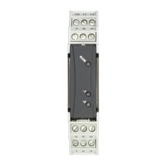
Page 11: Leds And Key Function
Input feedback potentiometer for motorized valves Leds and key function Meaning of status lights (Led) • Flashing during start-up and when PL500 is offline • Fixed ON with PL500 on RUN OUT1 • Normally it indicates the status of output OUT1 OUT2 •... -
Page 12: Synchronized Tuning
Synchronized Tuning Select 4 on parameter 31 (Tune). This procedure has been conceived to calculate correct PID values on multi-zone systems, where each temperature is influenced by the adjacent zones. Writing on “Autotuning state” on Outputs schedule, the controller works as follows: “Autotuning state”... -
Page 13: Dual Action Heating-Cooling
Dual Action Heating-Cooling PLE500-8AD is suitable also for systems requiring a combined heating-cooling action.The command output has to be configured as PID for Heating (par. 33 -greater than 0), while the alarm 1 has to be configured as Cooling (value 9 [cool] on par. 56 (Alarm 1)). The command output must be connected to the actuator responsible for heating, while the alarm will control cooling action. -
Page 14: Soft-Start Function
The par. 44 has the same meaning as the heating time cycle. Par. 41 (Cooling Fluid) pre-selects the proportional band multiplier (Par. 42) and the cooling PID cycle time basing on the type of cooling fl uid: ..t. Par. 41 Cooling fl... - Page 15 Absolute alarm or threshold alarm referred to command setpoint active over (Alarm1 = 6) Comand Spv Hysteresis parameter > 0 Absolute alarm referred to command setpoint. Hysteresis Alarm Spv value greater than “0” (Par. 58 > 0). . . Time Alarm output...
-
Page 16: Configuration Parameters Table
Lower deviation alarm (Alarm1 = 5) Comand Spv Lower deviation alarm value of alarm setpoint greater than “0” Hysteresis parameter > 0 and hysteresis value greater than “0” (Par. 58 > 0). . . With hysteresis value less than “0” ( <... - Page 17 Lower Linear Input Range AN1 lower limit only for linear input. Ex: with input 4..20 mA this parameter takes value associated to 4 mA. -32767..+32767, Default: 0. Upper Linear Input Range AN1 upper limit only for linear input. Ex: with input 4..20 mA this parameter takes value associated to 20 mA.
-
Page 18: Group Boutput And Regulation
GROUP B OUTPUT AND REGULATION Command Output Command output type selection Command Q1; Alarm 1 Q2; Alarm 2 AO (0..20 mA). (Default) Command Q1; Alarm 1 Q2; Alarm 2 AO (4..20 mA). Valve command: Q1 (open) - Q2 (close); Alarm 1 AO (0..20 mA) Valve command: Q1 (open) - Q2 (close);... - Page 19 Command Reset Type of reset for state of command contact (always automatic in P.I.D. functioning) Automatic reset (Default) Manual reset (see par. 10.10) Manual reset stored (keeps relay status also after an eventual power failure) Command Delay Command delay (only in ON / OFF functioning). -3600..+3600 seconds.
-
Page 20: Group Cautotuning And P.i.d
GROUP C AUTOTUNING AND P.I.D. Tune Autotuning type selection. Disabled. (Default) Automatic. Calculation of P.I.D. parameters at starting and at command setpoint modification. Manual (P.I.D. with automatic parameters calculation by “Autotuning state” on Outputs schedule) Once (P.I.D. with parameters calculation only once at starting) Synchronized. - Page 21 Cooling Fluid Type of refrigerant fluid for heating / cooling PID. Enable cooling output on par. AL.1 or AL.2. Air. (Default) Water Proportional Band Multiplier Proportional band for cooling action is done by the value of par. 30 multiplied for this value. 100(1.00)...500(5.00).
-
Page 22: Group Dalarm 1
GROUP D ALARM 1 Alarm 1 The alarm intervention is related to Alarm 1. Disabled. (Default) Absolute alarm (threshold) referred to process active above Absolute alarm (threshold) referred to process active below Band alarm Upper deviation alarm Lower deviation alarm Absolute alarm referred to active setpoint above Absolute alarm referred to active setpoint below Status alarm (active in RUN / START) -
Page 23: Group F - Soft-Start
63÷67 Reserved Parameters - Group D Reserved parameters - Group D GROUP E SOFT-START Soft-Start Type Enables and selects soft-start type Disabled (Default) Gradient Percentage Soft-Start gradient Rise / fall gradient for soft-start. 1..10000 Digit/hour (tenths of degree/hour if temperature). (Default: 1000) Soft-Start Percentage Value of the output percentage during Soft-start. -
Page 24: Group H - Retransmission
Overcurrent Alarm Threshold Overcurrent alarm threshold Alarm disabled. (Default) 0.1-200.0 Ampere Heater Break Alarm Delay Delay for Heater Break Alarm and overcurrent alarm 0...3600 s. (Default: 15 s) 95÷99 Reserved Parameters - Group G Reserved parameters - Group G GROUP G RETRANSMISSION 100 Retransmission Retransmission for output 0/4..20 mA. -
Page 25: Group I - Serial
GROUP H SERIAL 111 Slave Address Selects slave address for serial communication when all DIP 1 contacts are set on OFF 1...254. Default: 247. 112 Baud Rate Selects slave address for serial communication when all DIP 2 contacts are set on OFF 4800 bit/s 9600 bit/s 19200 bit/s (Default) -
Page 26: Inputs, Outputs E Commands
124 Error Value Output Defines values to be assumed by the outputs in case of error or off-line. Q1 (0 = off; 1 = on) Default: 0 Bit 0 Bit 1 Q2 (0 = off; 1 = on) Default: 0 125 Analogue Output Type Select the type of Analogue Output 0...20 mA... -
Page 27: Start / Stop Command
Start / Stop Command 10.3 Start / Stop Command 8bit unsigned Defines the controller status = STOP = START Heating output percentage 10.4 Heating output percentage 16bit unsigned Defines the command output percentage. In case of double loop, defines the heating output command percentage. -
Page 28: Digital Outputs Status
Digital outputs status 10.9 Digital outputs status 8bit unsigned Defines the status of digital outputs. The reading is managed in bit. bit 0 Q1 output status (0 = OFF, 1 = ON) bit 1 Q2 output status (0 = OFF, 1 = ON) Command output reset 10.10 Command output reset 8bit unsigned... - Page 29 Notes / Updates 2 On activation, the output is inhibited if the controller is in alarm mode. Activates only if alarm condition reappers, after that it was restored. User manual - PLE500-8AD -...
- Page 30 Table of configuration parameters GROUP A ANALOGUE INPUT Sensor 16 Degree 16 Lower Linear Input Upper Linear Input Potentiometer Value Linear Input over Limits Offset Calibration Gain Calibration Latch-On 10 Filter 11÷15 Reserved Parameters - Group A GROUP B OUTPUT AND REGULATION 16 Command Output 17 Initial State 18 Action type...
- Page 31 56 Alarm 1 22 57 Alarm 1 State Output 58 Alarm 1 Hysteresis 59 Alarm 1 State Error 60 Alarm 1 State Stop 61 Alarm 1 Reset 62 Alarm 1 Delay 63÷67 Reserved Parameters - Group D GROUP E SOFT-START 80 Soft-Start Type 81 Soft-Start gradient 82 Soft-Start Percentage...
- Page 32 131 Current Transformer Output 132÷136 Reserved Parameters - Group J Command setpoint 16bit signed Alarm 1 setpoint 16bit signed Start / Stop Command 8bit unsigned Heating output percentage 16bit unsigned Cold output percentage 16bit unsigned Cold junction temperature 16bit signed Error Flags 32bit unsigned Real command setpoint 16bit signed Digital outputs status 8bit unsigned...
-
Page 33: Norme Di Sicurezza
Introduzione Il PLE500-8AD integra in un unico dispositivo gli elementi fondamentali del loop di controllo: lettura della sonda di temperatura, controllo dell’uscita di regolazione digitale, lettura e controllo della corrente che passa attraverso il carico grazie all’ingresso per il trasformatore amperometrico. Completano il dispositivo funzioni come gli allarmi, la gestione di impianti a doppia azione caldo/ freddo e la possibilità... -
Page 34: Precauzioni Per L'uso Sicuro
Un malfunzionamento nel controllore digitale può occasionalmente rendere impossibili le operazioni di controllo o bloccare le uscite di allarme, con conseguenti danni Warning! materiali. Per mantenere la sicurezza, in caso di malfunzionamento, adottare misure di sicurezza appropriate; ad esempio con l’installazione di un dispositivo di monitoraggio indipendente e su una linea separata. -
Page 35: Identificazione Del Modello
Identificazione del modello Alim. 12/24Vdc ±15% (fornita dal PL500 attraverso il bus) + 1 ingresso analogico PLE500-8AD + 2 uscite logiche 24Vdc/50mA + 1 uscita 0/4..20mA + RS485 + CT Dati tecnici Caratteristiche generali Condizioni Temperatura: 0-45°C; umidità 35..95 RH%... -
Page 36: Dimensioni Ed Installazione
Sequenza di montaggio del PL500 e dei moduli di espansione PLE500 Il PL500 con i relativi moduli di I/O prevede il montaggio e la connessione tramite apposito bus alloggiato nell’incavo della barra DIN. I moduli di I/O (serie PLE500-xAD) verranno automaticamente numerati ad ogni accensione, assegnando il numero 1 al primo modulo I/O collegato alla destra del PL500, il numero 2 a quello seguente e così... -
Page 37: Collegamenti Elettrici
10 11 12 10 11 12 13 14 15 16 17 18 19 20 21 22 23 24 Procedere con il montaggio di tutti i moduli nell’ordine richiesto fino alla completa composizione del plc. 9 10 10 11 12 13 14 15 16 17 18 19 20 21 22 23 24 Non è... - Page 38 In fi gura: sensore di pressione. Collegare l’alimentazione esterna sui contatti P e N. Per segnali normalizzati in corrente 0/4..20mA con sensore a due fi li (necessita di alimentazione esterna, ad esempio quella del PL500) • Rispettare le polarità 4...20mA...
-
Page 39: Funzione Dei Led E Del Tasto
Ingresso Potenziometro di retroazione per valvole motorizzate Funzione dei led e del tasto Significato delle spie di stato (led) • Lampeggia durante lo start-up e con PL500 offline • Accesso fisso con PL500 in RUN OUT1 • Indica lo stato dell’uscita OUT1. -
Page 40: Tuning "Sincronizzato
Tuning “sincronizzato” Impostare 4 sul parametro 31 (Tune). La procedura sincronizzata è stata realizzata per permettere di calcolare valori corretti del P.I.D. su sistemi multizona, dove ogni temperatura è influenzata dalle zone adiacenti. Scrivendo su “Autotuning state” nella scheda Outputs il regolatore esegue quanto segue: Valore “Autotuning state”... -
Page 41: Funzionamento In Doppia Azione (Caldo-Freddo)
Funzionamento in doppia azione (caldo-freddo) Il PLE500-8AD consente la regolazione anche su impianti che prevedono un’azione combinata caldo-freddo. L’uscita di comando deve essere configurata in modalità PID (par. 33 maggiore di 0) e allarme 1 o 2 configurato come uscita refrigerante (valore 9 [cool] su parametro 56 (Alarm 1). L’uscita di comando va collegata all’attuatore responsabile dell’azione caldo, l’allarme comanderà... -
Page 42: Funzione Soft-Start
Il par.44 ha lo stesso signifi cato del tempo di ciclo per l’azione caldo. Il par. 41 (Cooling Fluid) pre-seleziona il moltiplicatore di banda proporzionale(Par. 42) ed il tempo di ciclo del PID freddo in base al tipo di fl uido refrigerante: Par. - Page 43 Allarme assoluto o allarme di soglia riferito al setpoint di comando attivo sopra (Alarm1 = Comand Spv Hysteresis parameter > 0 Allarme assoluto riferito al setpoint di comando. Valore di Alarm Spv isteresi maggiore di “0” (Par. 58 > 0). .
-
Page 44: Tabella Parametri Di Configurazione
Allarme di deviazione inferiore (Alarm1 = 5) Comand Spv Allarme di deviazione inferiore valore di setpoint allarme Hysteresis maggiore di “0” e valore di isteresi maggiore di “0” (Par. 58 parameter > 0 > 0). . . Alarm Spv Alarm Spv N.B.: con isteresi minore di “0”... - Page 45 Upper Linear Input Limite superiore dell’ingresso analogico solo per normalizzati. Es: con ingresso 4..20 mA questo parametro assume il valore associato a 20 mA -32767..+32767. Default:10000 Potentiometer Value Selezione il valore del potenziometro 1..150 kohm. Default: 10kohm Linear Input over Limits In caso di ingresso lineare, permette al processo di superare i limiti (Par.
-
Page 46: Gruppo Buscite E Regolazione
GRUPPO B USCITE E REGOLAZIONE Command Output Seleziona l’uscita di comando Comando Q1; Allarme 1 Q2; Allarme 2 AO (0..20 mA). (Default) Comando Q1; Allarme 1 Q2; Allarme 2 AO (4..20 mA). Comando valvola: Q1 (apri) - Q2 (chiudi); Allarme 1 AO (0..20 mA) Comando valvola: Q1 (apri) - Q2 (chiudi);... - Page 47 Command Reset Tipo di riarmo del contatto di comando (sempre automatico in funzionamento PID) Riarmo automatico (Default) Reset manuale (riarmo/reset manuale vedi par. 10.10) Reset manuale memorizzato (mantiene lo stato del relè anche dopo un eventuale mancanza di alimentazione) Command Delay Ritardo comando (solo in funzionamento ON / OFF).
-
Page 48: Gruppo Cautotuning E P.i.d
GRUPPO C AUTOTUNING E P.I.D. Tune Selezione il tipo di autotuning Disabilitato (Default) Automatico (P.I.D. con calcolo dei parametri automatico) Manuale (P.I.D. con calcolo parametri automatico lanciato da “Autotuning state” nella scheda Outputs) Once (P.I.D. con calcolo dei parametri solo una volta alla riaccensione) Tuning sincronizzato. - Page 49 Cooling Fluid Tipo di fluido refrigerante in modalità P.I.D. caldo / freddo. Abilitare l’uscita freddo nel parametro AL.1 o AL.2. Aria (Default) Olio Acqua Proportional Band Multiplier Moltiplicatore di banda proporzionale. La banda proporzionale per l’azione freddo è data dal valore del par.
-
Page 50: Gruppo Dallarme 1
GRUPPO D ALLARME 1 Alarm 1 Selezione allarme 1. Disabilitato (Default) Allarme assoluto (soglia) riferito al processo attivo sopra Allarme assoluto (soglia) riferito al processo attivo sotto Allarme di banda Allarme di deviazione superiore Allarme di deviazione inferiore Allarme assoluto riferito al setpoint attivo sopra Allarme assoluto riferito al setpoint attivo sotto Allarme di stato (attivo in RUN/START) Ausiliario attuatore freddo (Azione freddo in doppio loop) -
Page 51: Gruppo F - Soft-Start
63÷67 Reserved Parameters - Group D Parametri riservati - Gruppo D GRUPPO E SOFT-START Soft-Start Type Abilita e seleziona il tipo di soft-start Disabilitato (Default) Gradiente Percentuale Soft-Start gradient Gradiente di salita/discesa per soft-start 1..10000 Digit/ora (decimi di grado/ora se temperatura). (Default: 1000) Soft-Start Percentage Percentuale dell’uscita durante la funzione di soft-start 0..100%. -
Page 52: Gruppo H - Retransmission
Overcurrent Alarm Threshold Soglia di intervento per l’allarme di sovracorrente Allarme disabilitato. (Default) 0.1-200.0 Ampere Heater Break Alarm Delay Tempo di ritardo per l’intervento del Heater Break Alarm e dell’allarme di sovracorrente. 0...3600 s. (Default: 15 s) 95÷99 Reserved Parameters - Group G Parametri riservati - Gruppo G GRUPPO G RETRANSMISSION... -
Page 53: Gruppo I - Seriale
GRUPPO H SERIALE 111 Slave Address Seleziona l’indirizzo dello slave per la comunicazione seriale quando tutti i contatti di DIP1 sono su OFF 1...254. Default: 247. 112 Baud Rate Seleziona il baud rate per la comunicazione seriale quando tutti i contatti di DIP2 sono su OFF 4800 bit/s 9600 bit/s 19200 bit/s (Default) - Page 54 GRUPPO I ESPANSIONE 121 Expansion Module Abilita la modalita “Modulo di espansione”. Disabled (Default) Enabled 122 Initial Value Output Seleziona lo stato delle uscite all’accensione. Bit 0 Q1 (0 = off; 1 = on) Default: 0 Bit 1 Q2 (0 = off; 1 = on) Default: 0 123 Error Mode Output Definisce se l’uscita deve commutare in uno stato predefinito nel caso di errore o off-line.
-
Page 55: Inputs, Outputs E Commands
132÷136 Reserved Parameters - Group J Parametri riservati - Gruppo J Inputs, Outputs e Commands Setpoint di comando 10.1 Setpoint di comando 16bit signed Questo oggetto definisce il setpoint di comando -32767...32767 [digit] (gradi.decimi per sensori di temperatura) Setpoint allarme 1 10.2 Setpoint allarme 1 16bit signed Questo oggetto definisce il setpoint dell’allarme 1. -
Page 56: Setpoint Di Comando Reale
bit 16 Errore banco eeprom tarature bit 17 Errore banco eeprom costanti di taratura bit 18 Errore banco eeprom parametri bit 19 Errore banco eeprom setpoint bit 20 Errore banco eeprom dati scorta A bit 21 Errore banco eeprom dati scorta B bit 22 Errore banco eeprom dati scorta C Setpoint di comando reale... -
Page 57: Stato Autotuning
Stato autotuning 10.13 Questo oggetto definisce lo stato dell’autotuning e dipende dall’impostazione del parametro 31. Auto tuning 8bit unsigned RO Se par. 31 = 1 Funzione autotuning OFF Autotuning in corso Auto tuning 8bit unsigned R/W Se par. 31 = 2 Funzione autotuning OFF Funzione autotuning ON Auto tuning 8bit unsigned R/W... - Page 58 - PLE500-8AD - Manuale d’uso...
- Page 59 Tabella delle configurazioni dei parametri GRUPPO A INGRESSO ANALOGICO Sensor 45 Degree 45 Lower Linear Input Upper Linear Input Potentiometer Value Linear Input over Limits Offset Calibration Gain Calibration Latch-On 10 Filter 11÷15 Reserved Parameters - Group A GRUPPO B USCITE E REGOLAZIONE 16 Command Output 17 Initial State...
- Page 60 56 Alarm 1 51 57 Alarm 1 State Output 58 Alarm 1 Hysteresis 59 Alarm 1 State Error 60 Alarm 1 State Stop 61 Alarm 1 Reset 62 Alarm 1 Delay 63÷67 Reserved Parameters - Group D GRUPPO E SOFT-START 80 Soft-Start Type 81 Soft-Start gradient 82 Soft-Start Percentage...
- Page 61 131 Current Transformer Output 132÷136 Reserved Parameters - Group J Setpoint di comando 16bit signed Setpoint allarme 1 16bit signed Comando Start/Stop 8bit unsigned Percentuale uscita caldo 16bit unsigned Percentuale uscita freddo 16bit unsigned Temperatura giunto freddo 16bit signed Flags errori 32bit unsigned Setpoint di comando reale 16bit signed Stato uscite digitali 8bit unsigned Riarmo comando 8bit unsigned...
- Page 62 - PLE500-8AD - Manuale d’uso...
- Page 64 Prima di utilizzare il dispositivo leggere con attenzione le informazioni di sicurezza e settaggio contenute in questo manuale. Proc. Cont. Eq. E498498 PIXSYS s.r.l. www.pixsys.net sales@pixsys.net - support@pixsys.net online assistance: http://forum.pixsys.net via Po, 16 I-30030 Mellaredo di Pianiga, VENEZIA (IT) Tel +39 041 5190518 2300.10.292-RevB...
Need help?
Do you have a question about the PL500 and is the answer not in the manual?
Questions and answers