
Related Manuals for Pixsys PLE500-6AD


Summary of Contents for Pixsys PLE500-6AD
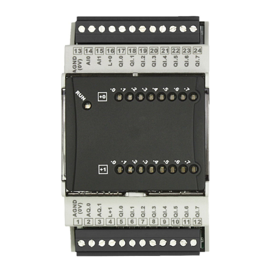
- Page 1 PLE500-6AD PL500 expansion module Modulo espansione per PL500 User manual / Manuale d’uso...
-
Page 3: Table Of Contents
Table of contents 1 Safety guidelines ................................4 Organization of safety notices ........................4 1.2 Safety Precautions ............................4 1.3 Precautions for safe use ..........................5 Environmental policy / WEEE ........................5 2 Model identification ............................... 5 3 Model identification ............................... 6 4 Technical data.................................. -
Page 4: Safety Guidelines
Introduction Thank you for choosing a Pixsys I/O module. PLE500-6AD is an expansion device for the PL500 model plc. It integrates digital inputs/outputs, analog inputs for normalized signals and analog current outputs in a single device. Communication with the PL500 is via bus on DIN rail, considerably simplifying wiring and the commissioning phase. -
Page 5: Precautions For Safe Use
Precautions for safe use Be sure to observe the following precautions to prevent operation failure, malfunction, or adverse affects on the performance and functions of the product. Not doing so may occasionally result in unexpected events. Do not handle the Digital Controller in ways that exceed the ratings. •... -
Page 6: Model Identification
Model identification Power supply 12..24 VDC ±15% 16 digital I/O PLE500-6AD 2 analog inputs 2 analog outputs Technical data General characteristics Operating conditions Temperature: 0-45°C; humidity 35..95 RH% without condensation Container DIN43880, 54 x 90 x 64 mm Container: PC UL94V0 self-extinguishing... -
Page 7: Dimension And Installation
64 mm 13 14 15 16 17 18 19 20 21 22 23 24 9 10 Attacco a guida DIN EN50022 PLE500-6AD Din rail mounting guide EN50022 Mounting sequence of the PL500 and of the PLE500 expansion modules The PL500 with the relevant I/O modules requires mounting and connection via the specific bus lodged in the hollow of the DIN rail. -
Page 8: Electric Connections
• Wiring of pins use crimped tube terminals or flexible/rigid copper wire with diameter 0.25 to 1.5 mm2 (min. AWG28, max. AWG16, operating temperature: min. 70°C). Cable stripping lenght 7 to 8 Wiring diagram 13 14 15 16 17 18 19 20 21 22 23 24 PLE500-6AD 9 10 11 12 - PLE500 - User manual... -
Page 9: Ple Module Power Supply
PLE module power supply 5.1.a 12..24 VDC provided by PLE DIN Bus Power supply of digital outputs 5.1.b Power supply of outputs 12..24 VDC ±15% – 100 VA. On these clips connected the power supply positive of the digital outputs. Analog inputs AI.0 and AI.1 5.1.c AI.0 AI.1... -
Page 10: Digital Outputs
Digital outputs 5.1.g QI.0 QI.7 QI.0 QI.7 12..24 VDC ± 15% digital output (based on the power supply of the 17 24 - 5 12 outputs)/ 700mA (Max 3A in total) Example of incremental encoder connection 5.1.h ENC1 ENC2 ENC3 ENC4 Use push-pull encoders 10 12... - Page 11 AI.0 offset calibration 10 AI.1 offset calibration Offset calibration Value added to or taken from the process displayed. -10000..+10000 [digit]. Default 0. 11 AI.0 gain calibration 12 AI.1 gain calibration Gain calibration. Value to be multiplied by the process in order to calibrate on the operating point. E.g.: to correct the 0..1000 operating scale that displays 0..1010, set the parameter to -1.0 -1000 (100.0%)...+1000 (+100.0%), Default: 0.0.
-
Page 12: Command And Operation Variable Table
26 Encoder/Counter setup 1 27 Encoder/Counter setup 2 28 Encoder/Counter setup 3 29 Encoder/Counter setup 4 Determines the mode of operation of the encoder input or mono-directional counter. Disabled (Default). Encoder X2 phase A-B (calculation on the fronts of signal A). Encoder X4 phase A-B (calculation on the fronts of signal A and B). - Page 13 Encoder/Counter commands 1 Encoder/Counter commands 2 Encoder/Counter commands 3 Encoder/Counter commands 4 These variables are used to send the commands to the encoder/counter inputs. When writing the suitable value, the following commands can be executed. No command (Default) Loading the counter with the preset value. Loading the counter with the preset value at the next front of the Z signal.
- Page 14 Value of digital outputs in error Q 0 block Value of digital outputs in error Q 1 block These two variables let you set the status of each individual digital output in case of communication error. Each bit corresponds to one of the digital outputs. By setting the bit to 1, in case of communication error, the output will be activated if the corresponding bit in the variable “Mask of status for digital outputs in error Q 0..1 block”...
- Page 15 Table of configuration parameters AI.0 type sensor AI.1 type sensor AI.0 input lower limit AI.1 input lower limit AI.0 input upper limit AI.1 input upper limit Linear input beyond limits AI.0 Linear input beyond limits AI.1 AI.0 offset calibration 10 AI.1 offset calibration 11 AI.0 gain calibration 12 AI.1 gain calibration 13 AI.0 latch-On function...
- Page 16 Encoder/Counter commands 4 Encoder/Counter calculations 1 Encoder/Counter calculations 2 Encoder/Counter calculations 3 Encoder/Counter calculations 4 Calculations at second encoder/counter 1 Calculations at second encoder/counter 2 Calculations at second encoder/counter 3 Calculations at second encoder/counter 4 Calculations at the tenth/second encoder/counter 1 Calculations at the tenth/second encoder/counter 2 Calculations at the tenth/second encoder/counter 3 Calculations at the tenth/second encoder/counter 4...
-
Page 17: Norme Di Sicurezza
Introduzione Grazie per aver scelto un modulo di I/O Pixsys. Il PLE500-6AD nasce come dispositivo di espansione per il plc modello PL500. Esso integra un un unico dispositivo ingressi/uscite digitali, ingressi analogici per segnali normalizzati e uscite analogiche in corrente. La comunicazione con il PL500 avviene tramite il bus su barra DIN, il che semplifica notevolmente il cablaggio e la fase di messa in servizio. -
Page 18: Precauzioni Per L'uso Sicuro
Un malfunzionamento nel controllore digitale può occasionalmente rendere impossibili le operazioni di controllo o bloccare le uscite di allarme, con conseguenti danni Warning! materiali. Per mantenere la sicurezza, in caso di malfunzionamento, adottare misure di sicurezza appropriate; ad esempio con l’installazione di un dispositivo di monitoraggio indipendente e su una linea separata. -
Page 19: Identificazione Del Modello
Identificazione del modello Alimentazione 12..24 VDC ±15% 16 I/O digitali PLE500-6AD 2 ingressi analogici 2 uscite analogiche Dati tecnici Caratteristiche generali Condizioni operative Temperatura: 0-45°C; umidità 35..95 RH% senza condensa Contenitore DIN43880, 54 x 90 x 64 mm Contenitore: PC UL94V0 auto-estinguente... -
Page 20: Dimensioni Ed Installazione
64 mm 13 14 15 16 17 18 19 20 21 22 23 24 9 10 Attacco a guida DIN EN50022 PLE500-6AD Din rail mounting guide EN50022 Sequenza di montaggio del PL500 e dei moduli di espansione PLE500 Il PL500 con i relativi moduli di I/O prevede il montaggio e la connessione tramite apposito bus alloggiato nell’incavo della barra DIN. -
Page 21: Collegamenti Elettrici
0.25 e 1.5 mm2 (min. AWG28, max. AWG16, temperatura operativa: min. 70°C). La lunghezza di spelatura è compresa tra 7 e 8 mm. Schema di collegamento 13 14 15 16 17 18 19 20 21 22 23 24 PLE500-6AD 9 10 11 12 Manuale d’uso - PLE500... -
Page 22: Alimentazione Modulo Ple
Alimentazione modulo PLE 5.1.a 12..24 VDC fornito dal PLE DIN Bus. Alimentazione uscite digitali 5.1.c Alimentazione uscite 12..24 VDC ±15% – 100 VA. L+0 L+1 16 4 Su questi morsetti collegare il positivo di alimentazione delle uscite 12..24 VDC digitali. Ingressi analogici AI.0 e AI.1 5.1.d AI.0 AI.1... -
Page 23: Uscite Digitali
Uscite digitali 5.1.h QI.0 QI.7 QI.0 QI.7 Uscita digitale 12..24 VDC ± 15% (in base all’alimentazione delle 17 24 - 5 12 uscite)/ 700mA (Max 3A totali) Esempio di collegamento encoder incrementale 5.1.i ENC1 ENC2 ENC3 ENC4 Utilizzare encoder push-pull. 10 12 Frequenza max. - Page 24 Calibrazione offset AI.0 10 Calibrazione offset AI.1 Calibrazione offset. Valore che si somma o sottrae al processo visualizzato. -10000..+10000 [digit]. Default 0. 11 Calibrazione guadagno AI.0 12 Calibrazione guadagno AI.1 Calibrazione guadagno. Valore che si moltiplica al processo per eseguire calibrazione sul punto di lavoro.
-
Page 25: Tabella Variabili Di Funzionamento E Comando
26 Setup encoder/contatore 1 27 Setup encoder/contatore 2 28 Setup encoder/contatore 3 29 Setup encoder/contatore 4 Determina la modalità di funzionamento dell’ingresso encoder o contatore monodirezionale. Disabilitato (Default). Encoder X2 fase A-B (conteggio sui fronti del segnale A). Encoder X4 fase A-B (conteggio sui fronti del segnale A e B) Encoder X2 fase A-B-Z (conteggio sui fronti del segnale A). - Page 26 Comandi encoder/contatore 1 Comandi encoder/contatore 2 Comandi encoder/contatore 3 Comandi encoder/contatore 4 Queste variabili vengono utilizzate per inviare i comandi agli ingressi encoder/contatore. Scrivendo l’opportuno valore, è possibile eseguire i seguenti comandi. Nessun comando (Default) Carica contatore con il valore di preset. Carica il contatore con il valore di preset al prossimo fronte del segnale Z.
- Page 27 Valore uscite digitali in errore blocco Q 0 Valore uscite digitali in errore blocco Q 1 Queste due variabili consentono di impostare lo stato di ogni singola uscita digitale in caso di errore di comunicazione. Ciascun bit corrisponde ad una delle uscite digitali. Impostando il bit a 1, in caso di errore di comunicazione, l’uscita verrà...
- Page 28 PLE500 - Manuale d’uso...
- Page 29 Tabella delle configurazioni dei parametri Tipo sensore AI.0 Tipo sensore AI.1 Limite inferiore ingresso AI.0 Limite inferiore ingresso AI.1 Limite superiore ingresso AI.0 Limite superiore ingresso AI.1 Ingresso lineare oltre limiti AI.0 Ingresso lineare oltre limiti AI.1 Calibrazione offset AI.0 10 Calibrazione offset AI.1 11 Calibrazione guadagno AI.0 12 Calibrazione guadagno AI.1...
- Page 30 Comandi encoder/contatore 4 Conteggi encoder/contatore 1 Conteggi encoder/contatore 2 Conteggi encoder/contatore 3 Conteggi encoder/contatore 4 Conteggi al secondo encoder/contatore 1 Conteggi al secondo encoder/contatore 2 Conteggi al secondo encoder/contatore 3 Conteggi al secondo encoder/contatore 4 Conteggi al decimo/secondo encoder/contatore 1 Conteggi al decimo/secondo encoder/contatore 2 Conteggi al decimo/secondo encoder/contatore 3 Conteggi al decimo/secondo encoder/contatore 4...
- Page 32 Prima di utilizzare il dispositivo leggere con attenzione le informazioni di sicurezza e settaggio contenute in questo manuale. Proc. Cont. Eq. E498498 PIXSYS s.r.l. www.pixsys.net sales@pixsys.net - support@pixsys.net online assistance: http://forum.pixsys.net via Po, 16 I-30030 Mellaredo di Pianiga, VENEZIA (IT) Tel +39 041 5190518 2300.10.272-RevC...
Need help?
Do you have a question about the PLE500-6AD and is the answer not in the manual?
Questions and answers