Table of Contents
Advertisement
Quick Links
Advertisement
Table of Contents

Related Manuals for Pixsys PL500


Summary of Contents for Pixsys PL500
- Page 1 PL500 Modular PLC User manual...
-
Page 3: Table Of Contents
General characteristics ..........................7 3.2 Hardware characteristics ........................... 7 3.3 Software characteristics ..........................7 Dimension and installation ............................7 Mounting sequence of the PL500 and of the PLE500 expansion modules........8 Electric connections..............................9 Wiring diagram ............................. 9 5.1.a Power supply ............................9 5.1.b CAN1 serial ............................ - Page 4 - PL500 - Manuale d’uso...
-
Page 5: Safety Guidelines
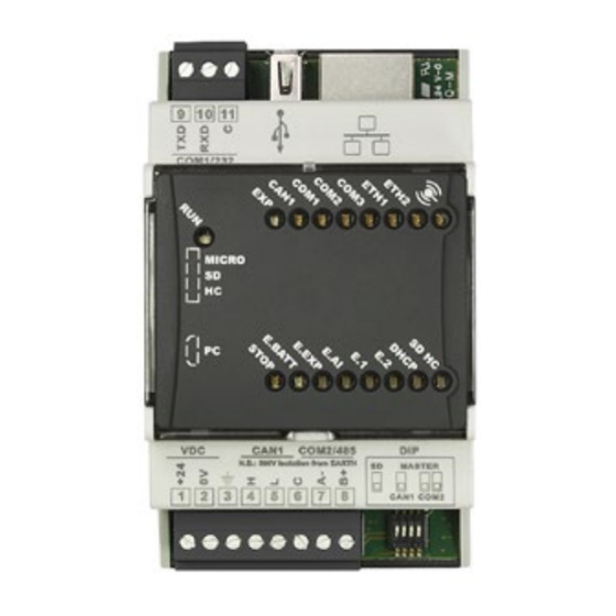
The PLC Pixsys PL500/PLE500 range features a modular and flexible structure. The PL500 CPU is a control unit and connectivity node, complete with serial RS485 and RS232 (Modbus RTU), Ethernet (Modbus TCP/IP) and CanOpen and is based on an ARM CORTEX A8 -1 GHz micropro- cessor. -
Page 6: Precautions For Safe Use
According to European Directive 2012/19/EU on waste electrical and electronic equipment and its implementation in accordance with national law, electric tools that have reached the end of their life must be collected separately and returned to an environmentally compatible recycling facility. - PL500 - User manual... -
Page 7: Model Identification
Model identification The PL500 series comes in 2 versions: PL500-335-1AD PLC DIN Rail 1 Ethernet, 1 RS485, 1 RS232, 1 CANopen PLC DIN Rail 1 Ethernet, 1 RS485, 1 RS232, 1 CANopen Movicon PL500-335-1AD-WEB Webserver Technical data General characteristics Supply voltage 12..24 VDC ±... -
Page 8: Mounting Sequence Of The Pl500 And Of The Ple500 Expansion Modules
1 to the first I/O module connected to the right of the PL500, the number 2 to the following one and so on, always moving towards the right side. The position of the various modules shall thus reflect the sequence set in the LogicLab project in the definition of the PLCEXP network. -
Page 9: Electric Connections
12..24Vdc CAN1 serial 5.1.b CAN MASTER: 120Ω terminator Connect any shield of the cable to terminal 3. CANH CANL RS232 / COM1 serial 5.1.c Connect any shield of the cable to terminal 3. TXD RXD User manual - PL500 -... -
Page 10: Rs485 / Com2 Serial
5.1.f Bus connector to be lodged in the hollow of the DIN rail to connect any I/O module to the PL500. For the mounting sequence see paragraph 1.2. 5.1.g USB 2.0 port for Backup / Restore of the mass archiving functionalities and applications (the memory must be formatted in FAT/FAT32). -
Page 11: Dip Switch Settings (Internal)
IDX10 and IDX1. • If set to OFF (default position) the IP address is 192.168.0.99 (or the last one manually assigned using the TdControlPanel for the version PL500-335- 1AD-WEB). DHCP If set to ON, force the assignment of the IP address of the PLC through the DHCP function;... -
Page 12: Graphic Interface - Webserver Function
Graphic interface – Webserver function In the PL500-335-1AD-WEB version, the PL500 PLC makes a graphic interface available, with the possibility of developing synoptics with the Movicon 11 CE scada, such as the HMI terminals of the TD710, TD810, TD820 series. -
Page 13: Hmi_Movicon
Movicon 11 to be run automatically when starting the device. The functions of the Movicon scada are available in all the HMIs and in the PL500 in the “WEB” version (PL500- 335-1AD-WEB) The “START” button starts the Movicon project (and the file upload service) manually. -
Page 14: Winvnc
VNC is “1234”. Suite LogicLab Suite LogicLab is Pixsys development environment to program the PLC PL500 and the entire family of operator terminals and PanelPCs. The suite can be downloaded from the download area of the pixsys.net website after having registered and does not require any activation code. -
Page 15: Connection To The Target
By default, the IP address of the HMI terminals is 192.168.0.100, that of the PL500 is 192.168.0.99; therefore, the PC with the development must have the same network and class (192.168.0.XXX in this case) but a different physical address (i.e. the last 3 digit of the IP address, with any number ranging between 1 and 255, other than 100). -
Page 16: Compiling And Downloading The Code
If you wish to change the display format simply select the variable and press the icon . From the appearing window select the desired format and confirm with “OK”. - PL500 - User manual... -
Page 17: Interfacing Movicon 11 With Logiclab
Start the software and choose the “Windows® X86 / X64” platform for the Panel-PCs and “Windows® CE” for the HMIs and for the “WEB” version PL500. If you are creating a new Movicon project following the Wizard, at the end you will see a driver configuration window; go directly to the “Driver configuration”... - Page 18 2. This field is self-compiled after entering the path of point 1. If you are using HMIs and the PL500, do not change the self-compiled field, in case of Panel-PC (TD750-TD850-TD900 etc.) enter the path where the project was downloaded (by default D:\LLExec\NomeMioProgettoLogicLab.sym.xml).
-
Page 19: Transferring The Movicon Code In The Target
“On-line” > “Target reboot” menu. From Movicon, enter the Pixsys driver configuration window and configure as follows: 1. Enter the folder where the simulator is working, set “All files (*.*) as filter for the file type and select the file NomeMio- ProgettoLogicLab.sym.simul. - Page 20 Limited liability Pixsys S.r.l. guarantees its electronic equipment for a period of 12 months from the invoice date. The Manufacturer’s liability is limited to repairing or replacing those parts that present manufacturing defects or that are returned with RMA (Return Material Authorization). Pixsys declines any liability for...
- Page 21 Prima di utilizzare il dispositivo leggere con attenzione le informazioni di sicurezza e settaggio contenute in questo manuale. Proc. Cont. Eq. E498498 PIXSYS s.r.l. www.pixsys.net sales@pixsys.net - support@pixsys.net online assistance: http://forum.pixsys.net via Po, 16 I-30030 Mellaredo di Pianiga, VENEZIA (IT) Tel +39 041 5190518 2300.10.273-RevD...
Need help?
Do you have a question about the PL500 and is the answer not in the manual?
Questions and answers