Table of Contents
Advertisement
INSTRUCTIONS
IX2-UCB
U-HSTR2
CONTROL BOX FOR IX2
HAND SWITCH
Optical Microscope Accessory
This instruction manual is for the Olympus Control Box model IX2-UCB and Hand Switch model
U-HSTR2, both for use with the IX2/GX motorized microscope. To ensure safety, optimum perfor-
mance and familiarize yourself fully with the use of the motorized microscope, we recommend that
you study this manual thoroughly before operating the system. Retain this instruction manual in an
easily accessible place near the work desk for future reference.
A X 6 4 4 4
Downloaded from
ManualsNet.com
search engine
Advertisement
Table of Contents

Related Manuals for Olympus IX2-UCB


Summary of Contents for Olympus IX2-UCB
- Page 1 HAND SWITCH Optical Microscope Accessory This instruction manual is for the Olympus Control Box model IX2-UCB and Hand Switch model U-HSTR2, both for use with the IX2/GX motorized microscope. To ensure safety, optimum perfor- mance and familiarize yourself fully with the use of the motorized microscope, we recommend that you study this manual thoroughly before operating the system.
- Page 2 Refer to your local Olympus distributor in EU for return and/or collection systems available in your country. NOTE: This product has been tested and found to comply with the limits for a Class A digital device, pursuant to Part 15 of the FCC Rules.
-
Page 3: Table Of Contents
Therefore, when using an objective with a short working distance, let the motorized revolving nosepiece escape once before pressing the objective switching button. NOMENCLATURE OPERATION Control Box IX2-UCB-2................................5 Turning Power On Functions of Indicator LEDs Hand Switch U-HSTR2 ................................5... -
Page 4: Important - Be Sure To Read This Section For Safe Use Of The Equipment
IMPORTANT The IX2-UCB (Type 2) control box is the basic module for controlling the drive functions of the IX2 microscope with motorized specification. It also incorporates the power supply for the microscope. It can be combined with one of the Type 2 microscope frames: IX81S1F-2, IX81S8F-2 and IX81F-2. - Page 5 (For the operating environmental condition, see chapter 3, “SPECIFICATIONS” on page 7.) 3. While the main switch of the IX2-UCB control box is set to “ I ” (ON), do not replace any module, plug or unplug any cable or switch the light path manually to prevent malfunction.
-
Page 6: Ix2 Series Motorized System
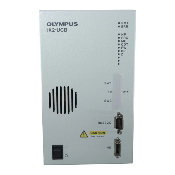
NOMENCLATURE Make sure to connect the Olympus-specified module to each connector. The PC in use should meet the IEC60950 requirements. If any non-specified equipment is used, Olympus cannot guarantee any performance of the system. Control Box IX2-UCB-2 Indicator LEDs · RMT: Lights at the time of remote control (in orange). - Page 7 IX2-UCB/U-HSTR2 Hand Switch U-HSTR2 }The button functions shown below are the functions in stand-alone mode or the initial functions set at the moment the system is started after having installed the IX2-BSW software (Ver. 01.03 or later) in the PC.
-
Page 8: Operation
OPERATION 2-1 Control Box IX2-UCB-2 Turning Power On (Fig. 1) Ensure that the modules to be used are connected properly. (P. 9) ² 1. Set the main switch @ to “ I ” (ON). 2. Ensure that the LED indicators ² corresponding to the connected mod- ules are lit. -
Page 9: Operation Selection Of The Dip Switches
IX2-UCB/U-HSTR2 2-3 Operation Selection of the DIP Switches }The allocated functions of the DIP switches are shown in the table below. # Make sure the main switch is set to “ ” (OFF) before setting the DIP switches. The unit detects the new settings only when the power is switched on, making those settings effective. -
Page 10: Specifications
Dimensions & weight Hand Switch U-HSTR2 Button functions Connects to the IX2-UCB-2 for use in the control of following operations. Also operable from a PC (which meets the IEC60950). Stand-alone mode or initial settings at the start of PC · FW–/FW+/CDT–/CDT+/MU–/MU+ buttons ·... -
Page 11: Troubleshooting Guide
Under certain conditions, performance of the microscope may be adversely affected by factors other than defects. If a problem occurs, please review the following list and take remedial action as appropriate. If you cannot solve the problem after checking the entire list, please contact your local Olympus representative for assistance. Problem... -
Page 12: Assembly
Rear panel 100 W halogen bulb lamp housing U-LH100L-3 IX-HLSH100 + U-RMT (extension cord) IX-LH100-3 + U-RMT (extension cord) Control Box IX2-UCB-2 Power cord Be sure to set the main switch to “ ” (OFF) before connecting cables. Hand Switch... - Page 13 Connecting the Power Cord (Figs. 5 & 6) Always use the power cord provided by Olympus. If no power cord is provided, please select the proper power cord by referring to the section “PROPER SELECTION OF THE POWER SUPPLY CORD” at the end of this instruction manual.
-
Page 14: Gx Series Motorized System
For the motorized modules that can be mounted on the system, see Chapter 1, "MOTORIZED SYSTEM DIAGRAM" on page 12 Using an unsuitable module hinders the system from manifesting its full performance. Combination of the IX2-UCB-2 control box and U-HSTR2 hand switch are required to control the motorized modules. Configuration of Instruction Manuals The instruction manuals for the motorized modules are provided separately as shown in the following table. -
Page 15: Motorized System Diagram
IX2-UCB/U-HSTR2 MOTORIZED SYSTEM DIAGRAM Be sure to connect the Olympus-specified module to each connector. If other module than specified is connected, Olympus can no longer warrant the performance of the system. Be sure to distribute the cables away from the lamp housing and the surroundings (particularly, take special care to the filter wheel). - Page 16 Attaching and Using the Cable Cover (Figs. 7 to 9) 1. Connect the connector @ of the motorized revolving nosepiece connec- tion cable. Fig. 7 2. Attach the cord clamp ³, provided with the GX71/GX51, to the bottom of the cable cover ² by adhesion. 3.
-
Page 17: Nomenclature
NOMENCLATURE CAUTION }The functions of the IX2-UCB-2 control box and U-HSTR2 hand switch described in the following pertain only to those available when this system configuration is used. The GX71/GX51 motorized system does not use the controls that are not described below. - Page 18 Hand Switch U-HSTR2 }As this system configuration does not use a PC, the functions of the hand switch buttons become as shown below when the cable is connected. (Stand-alone mode) }See page 5 for how to attach the indicator stickers and how to use the grouping panel sheets. FW+ (filter wheel switching) button For U-FWR...
- Page 19 IX2-UCB/U-HSTR2 (Note 1) The applicable microscope is only the GX71. Motorized Mirror Unit Turret (Note 2) Replace the manual mirror unit turret, provided as standard with the GX71, with GX-RTUA the motorized mirror unit turret. (Note 3) Remove the mirror units from the manual mirror unit turret and put them in the motorized mirror unit turret.
-
Page 20: Proper Selection Of The Power Supply Cord
If no power supply cord is provided, please select the proper power supply cord for the equipment by referring to “ Specifications ” and “ Certified Cord ” below: CAUTION: In case you use a non-approved power supply cord for Olympus products, Olympus can no longer warrant the electrical safety of the equipment. - Page 21 IX2-UCB/U-HSTR2 Table 2 HAR Flexible Cord APPROVAL ORGANIZATIONS AND CORDAGE HARMONIZATION MARKING METHODS Alternative Marking Utilizing Printed or Embossed Harmoniza- Black-Red-Yellow Thread (Length tion Marking (May be located on Approval Organization of color section in mm) jacket or insulation of internal wir-...
- Page 22 MEMO Downloaded from ManualsNet.com search engine...
- Page 23 Downloaded from ManualsNet.com search engine...
- Page 24 Manufactured by Shinjuku Monolith, 2-3-1 Nishi-Shinjuku, Shinjuku-ku, Tokyo 163-0914, Japan Distributed by 48 Woerd Avenue Waltham, MA 02453, U.S.A. 8F Olympus Tower, 446 Bongeunsa-ro, Gangnam-gu, Seoul, 06153 Korea Printed in Japan 20160122 M0000 AX6444 09 Downloaded from ManualsNet.com search engine...
Need help?
Do you have a question about the IX2-UCB and is the answer not in the manual?
Questions and answers