Advertisement
INSTRUCTIONS
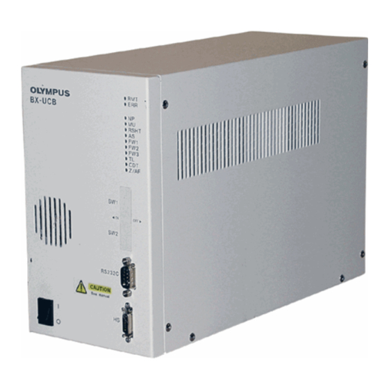
BX-UCB
U-HSTR2
CONTROL BOX
HAND SWITCH
This instruction manual is for the Olympus Control Box model BX-UCB and Hand Switch model U-
HSTR2, both for use with the BX2 motorized microscope. To ensure safety, optimum performance
and familiarize yourself fully with the use of the motorized microscope, we recommend that you
study this manual thoroughly before operating the system. Retain this instruction manual in an
easily accessible place near the work desk for future reference.
A X 9 9 4 4
Advertisement
Table of Contents

Related Manuals for Olympus BX-UCB


Summary of Contents for Olympus BX-UCB
- Page 1 CONTROL BOX HAND SWITCH This instruction manual is for the Olympus Control Box model BX-UCB and Hand Switch model U- HSTR2, both for use with the BX2 motorized microscope. To ensure safety, optimum performance and familiarize yourself fully with the use of the motorized microscope, we recommend that you study this manual thoroughly before operating the system.
-
Page 3: Table Of Contents
CONTENTS IMPORTANT — Be sure to read this section for safe use of the equipment. — NOMENCLATURE OPERATION Control Box BX-UCB ..................................5 Turning Power On Functions of Indicator LEDs Hand Switch U-HSTR2 ................................5 Attaching Indication Stickers Grouping Panel Sheet Operation Settings of the DIP Switches ...................... -
Page 4: Important - Be Sure To Read This Section For Safe Use Of The Equipment
(For the operating environmental condition, see chapter 3, “SPECIFICATIONS” on page 7.) 3. While the main switch of the BX-UCB control box is set to “ I ” (ON), do not replace any module, plug or unplug any cable or switch the light path manually to prevent malfunction (manual switching of the revolving nosepiece is permitted). - Page 5 BX-UCB/U-HSTR2 Caution If the equipment is used in a manner not specified by this manual, the safety of the user may be imperiled. In addition, the equipment may also be damaged. Always use the equipment as outlined in this instruction manual.
-
Page 6: Nomenclature
NOMENCLATURE Make sure to connect the Olympus-specified module to each connector. The PC in use should meet the IEC60950 requirements. If any non-specified equipment is used, Olympus cannot guarantee any performance of the system. Control Box BX-UCB Indicator LEDs · RMT: Lights at the time of remote control (in orange). - Page 7 BX-UCB/U-HSTR2 Hand Switch U-HSTR2 }The functions of the buttons on this hand switch are variable depending on whether the attached vertical illuminator is the BX- RFAA (on the upper stage) or the BX-RLAA (on the lower stage). The button functions can be set arbitrarily when the PC control (remote control) is used.
-
Page 8: Operation
OPERATION 2-1 Control Box BX-UCB Turning Power On (Fig. 1) Ensure that the modules to be used are connected properly. ² 1. Set the main switch @ to “ I ” (ON). 2. Ensure that the LED indicators ² corresponding to the connected mod- ules are lit. -
Page 9: Operation Settings Of The Dip Switches
BX-UCB/U-HSTR2 2-3 Operation Selection of the DIP Switches }The allocated functions of the DIP switches are shown in the table below. # Make sure the main switch is set to “ ” (OFF) before setting the DIP switches. The unit detects the new settings only when the power is switched on, making those settings effective. -
Page 10: Specifications
125(W) x 216(H) x 310(D) mm, approx. 5 kg (11 lb.) Hand Switch U-HSTR2 Button functions Connects to the BX-UCB for use in the control of following operations. (Can also be connected to Olympus AX70, AX80 or U-REMPS but the operation is not normal in this case.) When a PC is not used: ·... -
Page 11: Troubleshooting Guide
Under certain conditions, performance of the microscope may be adversely affected by factors other than defects. If a problem occurs, please review the following list and take remedial action as appropriate. If you cannot solve the problem after checking the entire list, please contact your local Olympus representative for assistance. Problem... -
Page 12: Assembly - If You Intend To Assemble The Unit By Yourself, Read This Section First
U-LH100-3 Rear panel Extension cord U-RMT Power cord Control Box BX-UCB Hand Switch U-HSTR2 Be sure to set the main switch to “ ” (OFF) before connecting cables. # The U-UCD8A and BX-RLAA cannot be used simultaneously. If both modules are used together, malfunction will... - Page 13 Connecting the Power Cord (Figs. 5 to 7) ³ Always use the power cord provided by Olympus. If no power cord is provided, please select the proper power cord by referring to the section “PROPER SELECTION OF THE POWER SUPPLY CORD” at the end of this instruction manual.
-
Page 14: Proper Selection Of The Power Supply Cord
If no power supply cord is provided, please select the proper power supply cord for the equipment by referring to “ Specifications ” and “ Certified Cord ” below: CAUTION: In case you use a non-approved power supply cord for Olympus products, Olympus can no longer warrant the electrical safety of the equipment. - Page 15 BX-UCB/U-HSTR2 Tableau 2 – Câbles souples Organisations officielles et méthode harmonisée de marquage des câbles Méthode de marquage alterna- tive, utilisant des gaines de Marque harmonisée, imprimée conducteurs colorées Noir- ou gravée (peut être posée sur Organisation officielle Rouge-Jaune. (Longueur du le câble ou sur la gaine isolante...
- Page 16 Shinjuku Monolith, 3-1, Nishi Shinjuku 2-chome, Shinjuku-ku, Tokyo, Japan Wendenstraße 14-18, 20097 Hamburg, Germany 3500 Corporate Parkway, P.O. Box 610, Center Valley, PA 18034-0610, U.S.A. One Corporate Drive, Orangeburg, NY 10962, U.S.A. 491B River Valley Road, 12-01/04 Valley Point Office Tower, Singapore 248373 31 Gilby Road, Mount Waverley, VIC., 3149, Australia 5301 Blue Lagoon Drive, Suite 290 Miami, FL 33126, U.S.A.
Need help?
Do you have a question about the BX-UCB and is the answer not in the manual?
Questions and answers