Table of Contents
Advertisement
Quick Links
03251553
D
GB
NL
RUS
PL
F
www.ermaf.nl
Operating instructions
Heater RGA 00 ACU
Contents
Contents
Heater RGA 00 ACU . . . . . . . . . . . . . . . . . . . .
Contents . . . . . . . . . . . . . . . . . . . . . . . . . . . . . .
Safety. . . . . . . . . . . . . . . . . . . . . . . . . . . . . . . . .
Checking the usage . . . . . . . . . . . . . . . . . . . . .
Wiring . . . . . . . . . . . . . . . . . . . . . . . . . . . . . . . . 4
Commissioning. . . . . . . . . . . . . . . . . . . . . . . . . 8
Adjusting the heater. . . . . . . . . . . . . . . . . . . . 0
Cleaning . . . . . . . . . . . . . . . . . . . . . . . . . . . . .
Assistance in the event of malfunction . . . . 4
Maintenance . . . . . . . . . . . . . . . . . . . . . . . . . . 0
operation. . . . . . . . . . . . . . . . . . . . . . . . . . . . .
Accessories . . . . . . . . . . . . . . . . . . . . . . . . . .
Spare parts . . . . . . . . . . . . . . . . . . . . . . . . . . . 5
Technical data . . . . . . . . . . . . . . . . . . . . . . . . 6
Certification . . . . . . . . . . . . . . . . . . . . . . . . . . 7
Logistics . . . . . . . . . . . . . . . . . . . . . . . . . . . . . 7
Goods return form . . . . . . . . . . . . . . . . . . . . . 8
Contact . . . . . . . . . . . . . . . . . . . . . . . . . . . . . . 8
E
UA
CN
Safety
Safety
Please read and keep in a safe place
Please read through these instructions
carefully before installing or operating. Following the
installation, pass the instructions on to the opera-
tor. This unit must be installed and commissioned
in accordance with the regulations and standards
in force. These instructions can also be found at
www.ermaf.nl.
Explanation of symbols
▷
= Instruction
Liability
We will not be held liable for damage resulting from
non-observance of the instructions and non-com-
pliant use.
Safety instructions
Information that is relevant for safety is indicated in
the instructions as follows:
DANGER
Indicates potentially fatal situations.
WARNING
Indicates possible danger to life and limb.
CAUTION
Indicates possible material damage.
All interventions may only be carried out by qualified
gas technicians. Electrical interventions may only be
carried out by qualified electricians.
Persons under the age of 18 as well as persons with
reduced physical, sensory or mental capabilities or
lack of experience and knowledge are not allowed
to use, clean or service this device. Staying near the
device or its use is prohibited, even if said persons are
supervised or have been instructed on the safe use of
the devices and are aware of the resulting dangers.
Conversion, spare parts
All technical changes are prohibited. Only use OEM
spare parts.
Changes to edition 09.8
The following chapters have been changed:
-
Fully revised version
GB-1
Advertisement
Table of Contents

Related Manuals for ermaf RGA 100 ACU


Summary of Contents for ermaf RGA 100 ACU
-
Page 1: Table Of Contents
Safety Safety 03251553 Please read and keep in a safe place www.ermaf.nl Please read through these instructions Operating instructions carefully before installing or operating. Following the Heater RGA 00 ACU installation, pass the instructions on to the opera- tor. This unit must be installed and commissioned in accordance with the regulations and standards in force. -
Page 2: Checking The Usage
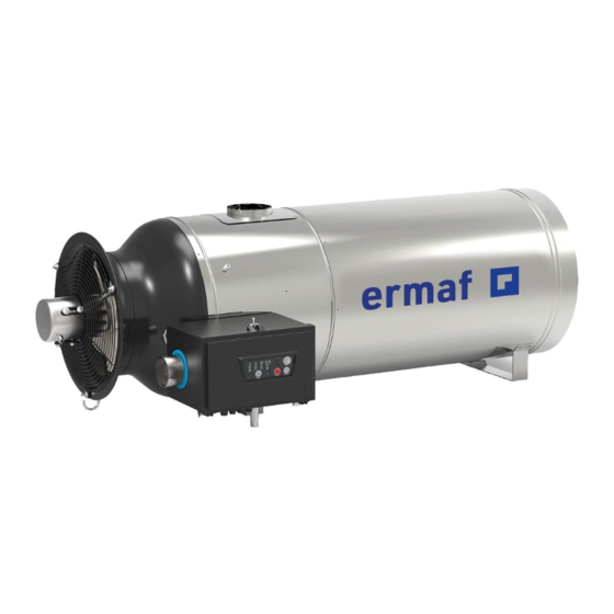
– No condensation permitted. Comply with ambi- ent temperature, see page 26 (Technical data). Stainless steel housing RGA 100 ACU Installation position Housing cover with burner control unit ACU ▷ Installation in the horizontal position. - Page 3 Chimney Connecting the gas supply ▷ The RGA 100 is set to the correct gas type as CAUTION specified in the purchase order. The RGA 100 is only deemed CE tested and ap- ▷ If you wish to use a different gas type, see proved when used with the coaxial chimney de- page 3 (Changing the gas type).
-
Page 4: Wiring
Tightness test Wiring ▷ The heater may only be disconnected from the CAUTION electrical power supply once the device has been Danger of electric shocks! switched off. – Before working on possible live components, Disconnect the system from the electrical power ensure the unit is disconnected from the power supply. - Page 5 Connection diagram Connecting the room thermostat ▷ The burner control unit is fitted with coded con- CAUTION nectors to prevent them being mixed up. To avoid damage to the heater RGA 100, please Potentiom- observe the following: eter – Provide post-cooling for the RGA 100. The (switch-on RGA ...
- Page 6 max. 5 A max. 2 A max. 264 V max. 264 V Remote reset Reset 10-24 V AC/DC N LT LV N LT LV MFA 1 MFA 2 X1 Gas X1 Gas 1. RGA 100 2. RGA 100 – 230 V AC ▷...
- Page 7 ▷ MFA , status signal (max. 2 A) Setting the switch-on delay ▷ If multiple heaters switch on at the same time, Possible parameterization options: – Fault NO (default setting): there can be a gas and/or power shortage on For example, the input for a horn can be set to individual devices.
-
Page 8: Commissioning
Commissioning MODE selection button (heater switched on): By pressing the MODE selection button, it is possible to switch between the different operat- CAUTION ing modes. To avoid damage to the heater RGA 100, please By pressing and holding the MODE selection observe the following: button in operating mode 2 Heating, the... - Page 9 +AUT Switching on ON/OFF MODE (RESET) • Press ON/OFF Mode E • The LED for the last selected operating mode will eBus address flash. A different operating mode can be selected within 2 s. If you retain the selection, the flashing light will change to permanently lit after 2 s.
-
Page 10: Adjusting The Heater
Adjusting the heater Mount the flue gas outlet in accordance with the local regulations. Make sure the outside air supply between the operating box and the chimney is connected. 4 Open the pressure test point for p ... - Page 11 Display and selection of the capacity setting CAUTION Only for testing in modulating operation. The RGA 100 is optimally adjusted and sealed for the low-fire rate. Afterwards, it is essential to switch 2 2.5 back to maximum capacity operation. ▷ This display is only possible when the heater is switched on.
-
Page 12: Cleaning
8 Read the burner pressure at the pressure test Flame signal ▷ The flame signal can be displayed when the point for p and readjust if necessary. Measure the λ and O values with a calibrated flue gas burner is operating. measuring instrument and adjust according to ... - Page 13 ▷ The electrical components are protected from ▷ If the RGA is heavily soiled, the safety grille can moisture by additional water drip edges on the be removed together with the fan: housing cover. Nevertheless, direct water influ- ence on the edges of the housing cover should be avoided.
-
Page 14: Assistance In The Event Of Malfunction
Internal connection diagram Assistance in the event of malfunction WARNING To avoid harm to persons and animals or damage to the heater, please observe the following: Safety temperature – Electric shocks can be fatal! Before working sensor on possible live components, ensure the unit is disconnected from the power supply. - Page 15 Press the RESET button to reset. The unit then ! Poor flame signal due to dirty or badly connected reverts to the last operating mode selected. flame rod. ▷ Possible faults: • Check the flame rod and clean it with fine abra- sive paper if necessary.
- Page 16 ? Error code F. and 2 flash alternately and the ? Error code A. and 5 flash alternately? light is red? The burner fan does not reach the required speed The fault could not be rectified. All start-up at- when starting up. tempts have been used and the burner control unit goes into lock-out.
- Page 17 ? Error code A. and 8 flash alternately? ? Error code C. and 1 flash alternately and the The main fan does not start during the start-up light is red after 5 minutes where applica- ble? attempts. Monitor temperature threshold (STM) of the safety temperature sensor has been exceeded.
- Page 18 ? Error code C. and 3 flash alternately and the ? Error code E. and 2 flash alternately and the light is red? light is red? Bridge on X16 between I1 and L disconnected. ! An adjustable parameter and the CRC check are ! Wiring fault or cable discontinuity.
- Page 19 ? Error code E. and 7 flash alternately? ? Error code U. and 5 flash alternately and the light is red? ! Fuse defective. • Check external fuse F1 (8 A). ! While a fault was pending, the unit has been successfully reset more than 5 ...
-
Page 20: Maintenance
0 Check the inside of the housing cover for traces Maintenance of dust, dirt or moisture. If you find such traces, the cause must be rectified at all times, e.g. by CAUTION sealing an open cable gland. To ensure that no damage occurs during operation ... -
Page 21: Checking The Safety Functions And Burner
Checking the safety functions and Accessories burner operation Room thermostat Use a room thermostat with a hysteresis of ± 1°C, WARNING 230 V, Type TH 215. Risk of explosion! – If these checks are not carried out, the gas valves might remain open allowing non-com- busted gas to escape. - Page 22 Connection kit Connection kit for natural gas Manual valve and gas hose to connect the gas combination control CG to the gas supply. R ¾" 1 , 4 0 Rp ¾" R ¾" Connection kit: R ¾" threaded connection, total length = 1.50 m, Order No.: N70000013. Connection kit for propane GP 14/GP 40 R ½"...
- Page 23 Chimney N50820003 Double-walled coaxial chimney with integrated flue gas and air supply route, category C33. ▷ Internal/External diameter: 150/250 mm, length: 2 – 5 m. CAUTION To avoid damage during operation, please observe the following instructions: – The RGA 100 is only deemed CE tested and approved when used with the coaxial chimney described below.
- Page 24 Application examples This example of application shows the chimney as a standard kit. ▷ Standard chimney kit, length 3,450 mm, Order No. N50820003 This example of application shows the chimney with the maximum installation length of 5 m. ▷ The chimney is routed sideways along the exterior wall rather than on the roof. Additional elbows from the accessories range are used for this purpose.
-
Page 25: Spare Parts
Motor Elnor BX275 N50820031 Safety grille for RGA 100 N50820029 Fan, 400 mm, white, 8 blades N70400004 Air inlet duct for RGA 100 ACU N50820048 Air hose, internal N50820049 Compression fitting (2 x) N50820018 Burner RGA 100 V4 without accessories... -
Page 26: Technical Data
N70400009 Air outlet pipe N70400010 Gas outlet pipe N50390117 Pressure test point N70400001 Burner Chip Card (BCC) for RGA 100 ACU N70400011 Ionization cable kit N70400012 Ignition cable kit N70400013 Cable harness for RGA 100 ACU Continuous control: capacity control from Technical data 60 –... -
Page 27: Certification
H: 9.6 m Ademco 2 GmbH propane: 6.3 kg/h, butane: 7.2 kg/h. Scan of the Declaration of conformity (D, GB) – see Connection rating: www.ermaf.nl 230 V AC, -15/+10%, 50 Hz, 1250 W. Current consumption I : 5.4 A. Eurasian Customs Union Air circulation: controlled air flow: ± 7000 m... -
Page 28: Goods Return Form
Please send returns back to your supplier. Contact Contact Ademco 2 GmbH Hansastraße 6 49504 Lotte (Büren) Germany Tel. +49 541 1214 8803 We reserve the right to make technical modifications Fax +49 541 1214 506 in the interests of progress. orders.ermaf@resideo.com, www.ermaf.nl GB-28...
Need help?
Do you have a question about the RGA 100 ACU and is the answer not in the manual?
Questions and answers