Table of Contents
Advertisement
058
D
GB
NL
PL
RUS
www.docuthek.com
Operating instructions
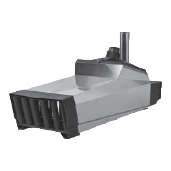
Heater Thermorizer TR 75
Contents
Contents
Contents . . . . . . . . . . . . . . . . . . . . . . . . . . . . . .
Checking the usage . . . . . . . . . . . . . . . . . . . . .
Installation . . . . . . . . . . . . . . . . . . . . . . . . . . . .
Tightness test . . . . . . . . . . . . . . . . . . . . . . . . . . 4
Wiring . . . . . . . . . . . . . . . . . . . . . . . . . . . . . . . . 4
Connection diagram. . . . . . . . . . . . . . . . . . . . . . 5
Connecting the room thermostat . . . . . . . . . . . . 5
Remote reset . . . . . . . . . . . . . . . . . . . . . . . . . . . 6
Multi-functional outputs . . . . . . . . . . . . . . . . . . . 6
Selecting the burner capacity. . . . . . . . . . . . . . . 7
Burner Chip Card (BCC) . . . . . . . . . . . . . . . . . . 7
Setting the switch-on delay . . . . . . . . . . . . . . . . 7
Commissioning . . . . . . . . . . . . . . . . . . . . . . . . . 7
Operation. . . . . . . . . . . . . . . . . . . . . . . . . . . . . . 8
Description. . . . . . . . . . . . . . . . . . . . . . . . . . . . . 8
Switching on . . . . . . . . . . . . . . . . . . . . . . . . . . . 8
Switching off . . . . . . . . . . . . . . . . . . . . . . . . . . . 8
Setting mode . . . . . . . . . . . . . . . . . . . . . . . . . . . 9
of the main fan . . . . . . . . . . . . . . . . . . . . . . . . . . 9
Adjusting the heater . . . . . . . . . . . . . . . . . . . . . 9
Cleaning . . . . . . . . . . . . . . . . . . . . . . . . . . . . .
Assistance in the event of malfunction . . . .
Maintenance . . . . . . . . . . . . . . . . . . . . . . . . . . 9
operation . . . . . . . . . . . . . . . . . . . . . . . . . . . . . 9
Accessories . . . . . . . . . . . . . . . . . . . . . . . . . . 0
Spare parts . . . . . . . . . . . . . . . . . . . . . . . . . . . 5
Technical data . . . . . . . . . . . . . . . . . . . . . . . . 7
Declaration of conformity . . . . . . . . . . . . . . . 7
Goods return form . . . . . . . . . . . . . . . . . . . . . 8
Contact . . . . . . . . . . . . . . . . . . . . . . . . . . . . . . 8
Safety
Please read and keep in a safe place
Please read through these instructions
carefully before installing or operating. Following the
installation, pass the instructions on to the opera-
tor. This unit must be installed and commissioned
in accordance with the regulations and standards
in force. These instructions can also be found at
www.docuthek.com.
Explanation of symbols
▷
= Instruction
Liability
We will not be held liable for damage resulting from
non-observance of the instructions and non-com-
pliant use.
Safety instructions
Information that is relevant for safety is indicated in
the instructions as follows:
DANGER
Indicates potentially fatal situations.
WARNING
Indicates possible danger to life and limb.
CAUTION
Indicates possible material damage.
All interventions may only be carried out by qualified
gas technicians. Electrical interventions may only be
carried out by qualified electricians.
Persons under the age of 18 as well as persons with
reduced physical, sensory or mental capabilities or
lack of experience and knowledge are not allowed
to use, clean or service this device. Staying near the
device or its use is prohibited, even if said persons are
supervised or have been instructed on the safe use of
the devices and are aware of the resulting dangers.
Conversion, spare parts
All technical changes are prohibited. Only use OEM
spare parts.
Transport
On receipt of the product, check that the delivery is
complete (see Part designations). Report any trans-
port damage immediately.
Storage
Store the product in a dry place. Ambient tempera-
ture: see Technical data.
GB-1
Advertisement
Table of Contents

Subscribe to Our Youtube Channel
Related Manuals for ermaf TR 75


Summary of Contents for ermaf TR 75
-
Page 1: Table Of Contents
Please read through these instructions Operating instructions carefully before installing or operating. Following the Heater Thermorizer TR 75 installation, pass the instructions on to the opera- tor. This unit must be installed and commissioned in accordance with the regulations and standards in force. -
Page 2: Checking The Usage
Type label Checking the usage Air circulation, electrical connection rating, rated heat TR 75 input, gas type, category, supply pressure, burner Heater with indirect combustion for agricultural sta- pressure, enclosure: see type label. bles and horticultural greenhouses. Depending on • Before installation, check whether the device is... - Page 3 Chimney CAUTION The TR is only deemed CE tested and approved when used with the coaxial chimney described in “Accessories”. ▷ Do not exceed the maximum length (5 m) of ▷ If the heater has not been used for a lengthy the chimney.
-
Page 4: Tightness Test
5 Open the cover of the burner control unit. supply. – The TR 75 must have an external 10 A fuse. – It must be possible to isolate the system from the power supply. The TR must be equipped with... -
Page 5: Connection Diagram
Connection diagram Connecting the room thermostat ▷ The burner control unit is fitted with coded plugs CAUTION to prevent them being mixed up. To avoid damage to the heater TR, please observe the following: Potentiom- – Provide post-cooling for the TR. The TR requires eter a continuous supply of 400 V AC (3NAC), 50 Hz. -
Page 6: Remote Reset
X1 Gas X1 Gas 6 Connect a room thermostat for 230 V AC. ▷ Method 1: power supply via the heater. 1. TR 75 2. TR 75 230 V AC ▷ An external remote reset may be connected to 230 V AC plug X5. -
Page 7: Selecting The Burner Capacity
Selecting the burner capacity Setting the switch-on delay ▷ If multiple heaters switch on at the same time, AC/DC 0-20 mA there can be a gas and/or power shortage on 64 V 10-24 V individual devices. To avoid this happening, ad- + –... -
Page 8: Operation
Operation Status indicator (light): red: fault yellow: standby/ready for operation green: TR in operation Optical interface: The PC software BCSoft can be used with the PC opto-adapter via this interface, see page 20 (Accessories). 7-segment display: MODE RESET ON/OFF Fault code Flame signal AUTO Number of operating cycles... -
Page 9: Setting Mode
▷ The main fan cools the heater down until it ▷ After a timeout of 20 s, the display will auto- reaches switch-off temperature. matically return to the initial mode. The display indicates “–”. CAUTION Checking the direction of rotation of the main –... - Page 10 ▷ If the burner does not ignite after several at- tempts, the CO value is set too low. ▷ Turn the restrictor half a turn in the + direction using the Allen key. 6 Place the analyzer sensor in the test point. 7 Ensure that there is no air in the gas system.
-
Page 11: Cleaning
▷ The flame signal is displayed for 20 s. Checking the low-fire rate setting Press the RESET button to exit the flame signal CAUTION display. To avoid damage to the heater TR, please observe ▷ If the flame signal < 2 µA, the fault F (flame fault) the following: 1 or 2 is displayed, see page 12 (Assistance –... -
Page 12: Assistance In The Event Of Malfunction
▷ The heater may only be disconnected from the electrical power supply once the device has been switched off and post-cooling is complete. Shut off the gas supply. 4 Check the cover on the burner control unit and the housing cover to ensure they are both tightly closed Assistance in the event of malfunction... - Page 13 Internal connection diagram Press the RESET button to reset. The unit then reverts to the last operating mode selected. ▷ Possible faults Display Fault type Flame fault eSTB2 Air fault (temperature sensor) Temperature fault Electronics fault Other possible faults 4 If the burner control unit does not respond even though all the possible faults have been rectified Burner fan...
- Page 14 ? Fault code F. and 2 flash alternately and the • Check the cable connection, cable and plug for damage or moisture. The plug must be fitted light is red? correctly. The fault could not be rectified. All start-up at- •...
- Page 15 ? Fault code A. and 4 flash alternately and the ! Fan motor defective. light is red? • Check motor. ! Wiring fault. Burner fan continues to operate when the burner control unit is in idle state. • Check wiring (plugs X21 and X12). ? Fault code A.
- Page 16 ? Fault code A. and 9 flash alternately and the ? Fault code C. and 2 flash alternately? light is red? Signal from safety temperature limiter (STL). The main fan continues to operate after the de- vice has been switched off. ! Temperature has been exceeded.
- Page 17 • The heater is too close to other heaters, see ? Fault code E. and 4 flash alternately and the page 2 (Installation). light is red? ! Incorrect CO value. The heater is not correctly set. • Adjust the heater, see page 9 (Adjusting the heater).
- Page 18 ? Fault code U. and 2 flash alternately and the ? A circulating dash is displayed rather than light is red? a fault code? ▷ After switching on the voltage, a circulating dash is displayed. ! Voltage supply is above the limit (programmable limit, e.g.
-
Page 19: Maintenance
Number of operating cycles Maintenance Check the number of operating cycles (heat- er ON): the number of operating cycles can be CAUTION displayed by pressing and holding the RESET To ensure that no damage occurs during operation button. The number of operating cycles is com- and maintenance, please observe the following posed as follows in alternating displays: instructions. -
Page 20: Accessories
▷ If the burner control unit responds in a different Pressure reducer way to that described, a fault has occurred, see Pressure reducer for LPG. page 12 (Assistance in the event of malfunc- tion). CAUTION The fault must be remedied before the system may be operated. - Page 21 Rp ¾" R ¾" Connection kit: R ¾" threaded connection, total length = 1.50 m, Order No.: N70000013. Connection kit for propane GP 14/GP 40 R ½" ø 6 mm TR 75 R ¾" R ½" R ½" R ½" Rp ¾" R ½"...
- Page 22 Wall bracket The wall bracket is the support and wall mounting for the heater. The position of the heater is fixed. Two wall mounts with angle brackets and fastening elements, Order No.: N70000002. Slide for the wall bracket The slide on the wall bracket enables the heater to be moved horizontally. 4 struts with fastening elements, Order No.: N70000015.
- Page 23 ▷ Any roof bushing depends on the roof construc- Chimney Double-walled coaxial chimney with integrated flue tion and must be ordered separately. gas and air supply route, category C33. Examples of application ▷ Internal/External diameter: 100/150 mm, maxi- This example of application shows the chimney as mum length: 5 m.
- Page 24 This example of application shows the chimney with In this example of application, the chimney is routed the maximum installation length of 5 m. sideways along the exterior wall rather than on the ▷ The telescopic pipe can be adjusted to a shorter roof.
-
Page 25: Spare Parts
TR 75 metal hose, 3/4" x 290 mm N70000039 TR 75 flange for metal hose N70000040 TR 75 vibration damper, Ø 30 x 15 x M8 x 10 N70000041 TR 75 rubber seal, U section, radial seal (per metre) GB-25... - Page 26 Item Order number Designation N70000042 TR 75 star ring, 12 mm N70000043 TR 75 vibration damper, Ø 30 x 40 x M8 x 10 N70000045 TR 75 rubber fastener N70000046 TR 75 status indicator N70000047 TR 75 temperature sensor N70000048...
-
Page 27: Technical Data
Technical data Declaration of conformity Gas types: II2ELL3B/P, natural gas H and L (gases of category 2); LPG, gaseous (gases of category 3): propane, propane/butane, butane. We, the manufacturer, hereby declare that the prod- Fused with 10 A. uct TR complies with the requirements of the listed NOx Class: depending on gas type up to Class 5. -
Page 28: Goods Return Form
Strohteweg 1, 49504 Lotte (Büren) T +31 315 338-911 German F +31 315 338-679 T +49 541 1214 702 We reserve the right to make technical modifications F +49 541 1214 506 in the interests of progress. orders.ermaf@elster.com, www.ermaf.nl GB-28...
Need help?
Do you have a question about the TR 75 and is the answer not in the manual?
Questions and answers