
Subscribe to Our Youtube Channel
Related Manuals for JYTEK PXIe-2722


Summary of Contents for JYTEK PXIe-2722
- Page 1 PXIe-2722 Chassis User Manual User Manual Version: V1.0.2 Revision Date: Nov 8 2021...
-
Page 2: Table Of Contents
Table of Contents 1. Introduction....................... 1 Overview......................1 Main Features....................1 2. Hardware........................2 Backplane Overview..................2 2.1.1 PXIe-2722G3 Backplane Architecture........... 2 2.1.2 PXIe-2722G2 Backplane Architecture........... 3 2.1.3 System Controller Slot................4 2.1.4 Peripheral Slot..................4 2.1.5 PXI Trigger Bus..................5 2.1.6 PXI Local Bus..................6 2.1.7 System Reference Clock and Synchronization Signal......6 Specifications....................8 2.2.1 Basic.......................8... - Page 3 Chassis identification in NI MAX..............45 5. Using PXIe-2722 Chassis..................47 Using PXIe-2722 with JYTEK PXI/PXIe Peripheral Modules......47 Using PXIe-2722 with National Instruments PXI/PXIe Peripheral Modules...47 5.2.1 Use National Instruments PXI/PXIe Peripheral Modules without synchronization:................... 47 5.2.2 Use National Instruments PXI/PXIe Peripheral Modules with synchronization:...................
- Page 4 Figure 36 Trigger Bus Routing Control..............44 Figure 37 Install NI MAX..................45 Figure 38 Change PXI Trigger Manager Setting............45 Figure 39 NI MAX GUI display JYTEK chassis and modules........46 Figure 40 Trigger Routing..................47 Figure 41 DAQmx Export Signal................48 Figure 42 DAQ Synchronization Reference Code..........48...
-
Page 5: Introduction
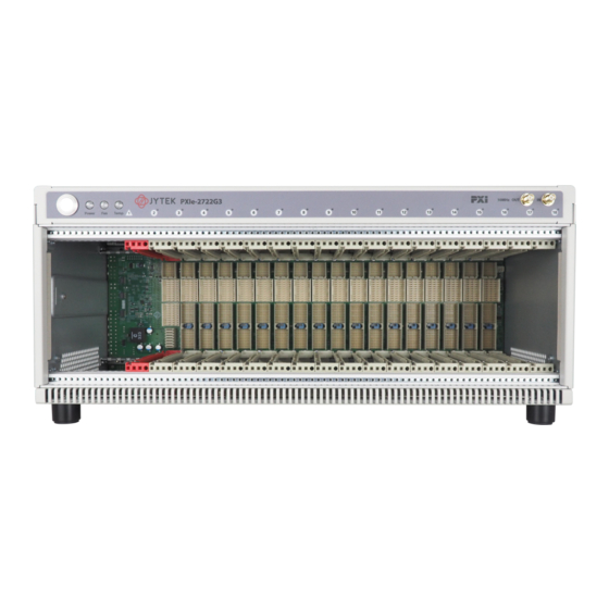
PXIe-2722 series are flexibility and high performance 18-slot all-hybrid PXIe chassis which features up to 24 GB/s system bandwidth and 58 W of power and cooling in every slot. Depanding on PCIe link speed capability, PXIe-2722 series provide two models as shown inTable 1. PCIe Link Speed... -
Page 6: Hardware
All of the PXIe peripheral slots can support PCIe Gen3 x8 link providing a maximum slot bandwidth of 8 GB/s. The system slot can support PCIe Gen3 x24 link (x8 + x16) and has a maximum system bandwidth of 24 GB/s. Figure 1 PXIe-2722 Gen3 Backplane Architecture PXIe-2722 Chassis | jytek.com | 2... -
Page 7: Pxie-2722G2 Backplane Architecture
4 GB/s. The 13 remaining peripheral slots have a PCIe Gen2 x4 link providing a maximum slot bandwidth of 2 GB/s. Figure 2 PXIe-2722 Gen2 Backplane Architecture Note: Slot2, slot6, slot11 and slot15 can support PCIe Gen2 x8, the remaining ... -
Page 8: System Controller Slot
PCIe switch board, and then downstream to every peripheral slot. The chassis can accommodate a maximum 4-slot width PXIe controller. 2.1.4 Peripheral Slot PXIe-2722 provides seventeen hybrid peripheral slots. It can accept the following peripheral modules: PXI Express Peripheral Module ... -
Page 9: Pxi Trigger Bus
2.1.5 PXI Trigger Bus Three trigger bus segments on the PXIe-2722 consist of a first segment from 1st to 6th slots, a second from 7th to 12th slots, and a third from 13th to 18th slots, with each trigger bus segment containing 8 trigger lines connecting all slots on the same segment, providing inter-module synchronization. -
Page 10: Pxi Local Bus
2.1.6 PXI Local Bus The local bus on PXIe-2722 is a daisy-chained bus that connects each peripheral slot with adjacent peripheral slots to the left and right, which by routing PXI Local Bus 6 signal between adjacent peripheral slots. - Page 11 Figure 6 System Reference Clock Default Behavior PXIe-2722 Chassis | jytek.com | 7...
-
Page 12: Specifications
Specifications 2.2.1 Basic Table 3 Basic Specification PXIe-2722 Chassis | jytek.com | 8... -
Page 13: Electrical
2.2.2 Electrical PXIe-2722 Chassis | jytek.com | 9... -
Page 14: System Synchronization Clock
Table 4 Electrical Specification 2.2.3 System Synchronization Clock PXIe-2722 Chassis | jytek.com | 10... -
Page 15: Physical And Enviornment
Table 5 System Synchronization Clock 2.2.4 Physical and Enviornment Table 6 Physical and Environment PXIe-2722 Chassis | jytek.com | 11... -
Page 16: Mechanical Dimensions
Mechanical Dimensions All dimensions are shown in mm (millimeters) Figure 7 Front View Figure 8 Left Side View PXIe-2722 Chassis | jytek.com | 12... - Page 17 Figure 9 Right Side View Figure 10 Rear View PXIe-2722 Chassis | jytek.com | 13...
- Page 18 Figure 11 Top View PXIe-2722 Chassis | jytek.com | 14...
- Page 19 Figure 12 Bottom View PXIe-2722 Chassis | jytek.com | 15...
-
Page 20: Front And Rear Panels
2.4.1 Front Panel Figure 13 Front Panel Location Feature Chassis Model Name Removable Feet Backplane Connectors Chassis Status LED Power Switch 10MHz REF CLK IN 10MHz REF CLK OUT Handle Table 7 Front Panel PXIe-2722 Chassis | jytek.com | 16... -
Page 21: Rear Panel
2.4.2 Rear Panel Figure 14 Rear Panel Location Feature Chassis Ground Screw FAN Switch AC Input Rear Output Vents Inhibit Switch Inhibit/Voltage Monitoring DB-9 Connector Table 8 Rear Panel PXIe-2722 Chassis | jytek.com | 17... -
Page 22: Inhibit/Voltage Monitoring Db-9 Connector
In the DEF (default) position, the front panel power button turns the power supply on/off, and in the MAN (manual) position, the Inhibit pin on the DB-9 connector turns the power supply on/off. Figure 16 Inhibit Switch PXIe-2722 Chassis | jytek.com | 18... -
Page 23: Fan Switch
Figure 17 FAN Switch 2.4.6 Chassis Status LED Table 9 Chassis Status LED 2.4.7 Fan Mode PXIe-2722 provides the smart fan control mechanism as blow curve. It provides two fan modes. Fan Mode Fan’s duty cycle Fan’s speed Note 1680 rpm ±10%... - Page 24 When the Fan Switch is set to HIGH mode, fans run at 100% duty cycle immdiately. The factory default fan control curve shows as following Figure. Figure 18 Fan Control Curve Figure 19 Position of temperature sensors PXIe-2722 Chassis | jytek.com | 20...
- Page 25 Note: For details about chassis temperature monitoring, please see JYDM utility on page 32. PXIe-2722 Chassis | jytek.com | 21...
-
Page 26: Chassis Cooling Considerations
For PXI/PXIe modules cooling, there are three fans on the rear panel draw cool air from the bottom side and front panel to be exhausted to the rear panel. Figure 20 PXI/PXIe Modules Cooling PXIe-2722 Chassis | jytek.com | 22... -
Page 27: Power Supply Cooling
2.5.2 Power Supply Cooling For power supply cooling, power supply’s fan draws cool air from the right side, to be exhausted through the left side of the chassis. Figure 21 Power Supply Cooling PXIe-2722 Chassis | jytek.com | 23... -
Page 28: Performance
PXI-69846H 109 MB/s PXI-69846H 109 MB/s Table 11 PCI Bus Throughput Note: PCI Bus theoretical maximum bandwidth is 132 MB/s. PXI-69846H is 4-ch 40 MS/s 16-bit digitizer, its bandwidth is 320 MB/s. PXIe-2722 Chassis | jytek.com | 24... - Page 29 Figure 22 PCI Bus Throughput for segment 1 PXIe-2722 Chassis | jytek.com | 25...
- Page 30 Figure 23 PCI Bus Throughput for segment 2 PXIe-2722 Chassis | jytek.com | 26...
- Page 31 Figure 24 PCI Bus Throughput for segment 3 PXIe-2722 Chassis | jytek.com | 27...
-
Page 32: Pcie Bus Throughput
PCIe Bus Throughput 3.2.1 PXIe-2722G3 PCIe Bus Throughput Table 12 PXIe-2722G3 PCIe Bus Throughput PXIe-2722 Chassis | jytek.com | 28... - Page 33 PXIe-2722 Chassis | jytek.com | 29...
- Page 34 Slot 1 is the system bandwidth test; its theoretical maximum bandwidth is 24 GB/s (PCIe Gen3 x24). Slot 2 to 18 are the slot bandwidth test; its theoretical maximum bandwidth is 8 GB/s (PCIe Gen3 x8). PXIe-2722 Chassis | jytek.com | 30...
-
Page 35: Pxie-2722G2 Pcie Bus Throughput
3.2.2 PXIe-2722G2 PCIe Bus Throughput Table 13 PXIe-2722G2 PCIe Bus Throughput PXIe-2722 Chassis | jytek.com | 31... - Page 36 PXIe-2722 Chassis | jytek.com | 32...
- Page 37 Slot 1 theoretical maximum bandwidth is 8 GB/s (PCIe Gen2 x16). Slot2, slot6, slot11 and slot15 can support PCIe Gen2x8, its theoretical maximum bandwidth is 4 GB/s. Other peripheral slots can support PCIe Gen2x4, its theoretical maximum bandwidth is 2 GB/s. PXIe-2722 Chassis | jytek.com | 33...
-
Page 38: Compatibility Test
Compatibility test PXIe-2722 Chassis | jytek.com | 34... - Page 39 PXIe-2722 Chassis | jytek.com | 35...
- Page 40 Table 14 Compatibility test PXIe-2722 Chassis | jytek.com | 36...
-
Page 41: Software
4. Software Introduction to JYDM JYDM (JYTEK Device Management) is the latest equipment management software of JYTEK. Its main functions are as follows: Support GUI information display and management of PXI-2/6 standard equipment. Support trigger configuration of PXI-9 standard chassis. - Page 42 Figure 26 JYDM GUI application program Note: JYTEK peripheral module driver has two parts: the shared common driver kernel software (FirmDrive) and the specific peripheral module driver. After firmware update of peripheral module, you need to cold restart your ...
-
Page 43: Chassis Environment Monitoring In Jydm
(T1 sensor is located on the top side of backplane, close to slot1.) Figure 28 Monitoring the Chassis Temperature Sensors Monitoring the chassis fan speed. (Fan1 module ia located on the rear side of chassis, close to slot1.) Figure 29 Monitoring the Chassis Fan Speed PXIe-2722 Chassis | jytek.com | 39... -
Page 44: Chassis Cooling Control In Jydm
Chassis cooling control in JYDM PXIe-2722 chassis allow user to control the cooling capability via JYDM. Figure 30 Chassis Cooling Control in JYDM Target Temperature specifies the chassis temperature at which the maximum fan speed (100% duty cycle) is achieved as shown in below figure. - Page 45 The factory default target temperature setting is 50°C. User can change target temperature to lower value (ex. 40°C), it will increase fan speed if the factory default setting could not fulfill the peripheral modules cooling requirement. Figure 32 Change Target Temperature to 40°C PXIe-2722 Chassis | jytek.com | 41...
-
Page 46: Reference Clock Status Display In Jydm
10MHz clock. A phase-lock loop (PLL) circuit on the backplane synchronizes the PXIe_CLK100 and external 10MHz clock, and then JYDM will display Synchronized and green indicator as shown in figure 34. Figure 34 Reference Clock Status Display for external clock source PXIe-2722 Chassis | jytek.com | 42... -
Page 47: Trigger Bus Routing Control In Jydm
Trigger Bus Routing Control in JYDM PXIe-2722 provides an interface to route PXI trigger bus. User can complete the following steps to route these trigger lines in JYDM. Clicking on My System item, set Default PXI Trigger Manger to JYTEK, and then click Save to save the settings. - Page 48 Figure 36 Trigger Bus Routing Control PXIe-2722 Chassis | jytek.com | 44...
-
Page 49: Chassis Identification In Ni Max
Open JYDM, set Valid PXI Resource Manager and Default PXI Trigger Manger to National Instruments, and then click Save to save the settings. Figure 38 Change PXI Trigger Manager Setting Open NI MAX after software installation and the devices can be identified: PXIe-2722 Chassis | jytek.com | 45... - Page 50 Figure 39 NI MAX GUI display JYTEK chassis and modules PXIe-2722 Chassis | jytek.com | 46...
-
Page 51: Using Pxie-2722 Chassis
This chapter provides the operation guides for PXIe-2722. Using PXIe-2722 with JYTEK PXI/PXIe Peripheral Modules Using PXIe-2722 with JYTEK PXI/PXIe peripheral modules is straightforward. JYTEK also provide a device management software to view the modules in the chassis. For more information, please visit our web www.jytek.com... - Page 52 But you can use “DAQmx Export Signal” to set appointed clock/trigger routing: Figure 41 DAQmx Export Signal DAQ synchronization reference code: Figure 42 DAQ Synchronization Reference Code PXIe-2722 Chassis | jytek.com | 48...
-
Page 53: Optional Equipment
6. Optional Equipment Rack Mount Kits JYTEK provides optional hardware for installation of PXIe-2722 chassis into a server or rack. The rack mounting kits dimension as following figure. All dimensions are shown in mm (millimeters). Figure 43 PXIe-2722 rack mount kits dimension... -
Page 54: About Jytek
7. About JYTEK JYTEK China Founded in June, 2016, JYTEK China is a leading Chinese test & measurement company, providing complete software and hardware products for the test and measurement industry. The company is a joint venture between Adlink Technologies and a group of experienced professionals form the industry. -
Page 55: Jytek Software Platform
FirmDrive, upon which many our future hardware will be based. In addition to our own developed hardware, JYTEK also rebrands Adlink’s PXI product lines. In addition, JYTEK has other rebranding agreements to increase our hardware coverage. It is our goal to provide the complete product coverage in PXI and PCI modular instrumentation and data acquisition. -
Page 56: Statement
8. Statement The hardware and software products described in this manual are provided by JYTEK China, or JYTEK in short. This manual provides the product review, quick start, some explaination for JYTEK PXIe-2722 chassis. The manual is copyrighted by JYTEK.
Need help?
Do you have a question about the PXIe-2722 and is the answer not in the manual?
Questions and answers