
Subscribe to Our Youtube Channel
Related Manuals for JYTEK PXIe-62780


Summary of Contents for JYTEK PXIe-62780
- Page 1 PXIe-62780 18-slot PXI Express Chassis User’s Manual Manual Rev.: 1.00 Revision Date: Jul.15,2016...
-
Page 2: Getting Service
Getting Service Contact us should you require any service or assistance. SHANGHAI JYTEK Co., Ltd. Web site: http://www.jytek.com Address: (201203) 300 Fang Chun Rd., Zhangjiang Hi-Tech Park, Pudong New Area, Shanghai, 201203 China Tel: +86-21-5047-5899 Fax: +86-21-5047-5899 Email: service@jytek.com Additional information, aids, and tips that help users perform tasks. -
Page 3: Table Of Contents
2.4 Rack Mounting ����������������������������������������������������������������������������������20 2�4�1 Powering Up the System ��������������������������������������������������������21 3 System Management & Configuration ��������������������������������������������������������22 3.1 Installing the Monitor Utility �������������������������������������������������������������22 3�2 Monitoring the PXIe-62780 ����������������������������������������������������������������23 3�2�1 Connect Control ���������������������������������������������������������������������23 3.2.2 Chassis Control and Alarm Threshold Setting ��������������������������25 3�2�3 Chassis Status �������������������������������������������������������������������������27 Appendix A - Troubleshooting and Maintenance ���������������������������������������������28... - Page 4 Table 1-2: Front Panel Indicators ���������������������������������������������������������������������� 6 Table 1-3: Rear Panel Legend ��������������������������������������������������������������������������� 8 Table 1-4: PXI Star Trigger Line Assignment �����������������������������������������������������11 Table 1-5: PXIe-62780 Reference Clock Priority �����������������������������������������������14 Table 2-1: Rack Mount Assembly Legend ��������������������������������������������������������20 Table 3-1: Supported Function Comparison Between SMBus Interface and RS- 232 Serial Port ��������������������������������������������������������������������������������22...
- Page 5 Figure 1-3: Left Side View ��������������������������������������������������������������������������������� 5 Figure 1-4: Rear View���������������������������������������������������������������������������������������� 5 Figure 1-5: PXIe-62780 Front Panel ������������������������������������������������������������������� 6 Figure 1-6: PXIe-62780 Rear Panel Connectors �������������������������������������������������� 7 Figure 1-7: Inhibit/ Voltage & Remote Monitoring Connectors �������������������������� 8 Figure 1-8: PXIe-62780 Backplane ��������������������������������������������������������������������� 9 Figure 1-9: Temperature Sensors on Backplane �������������������������������������������������...
-
Page 6: Introduction
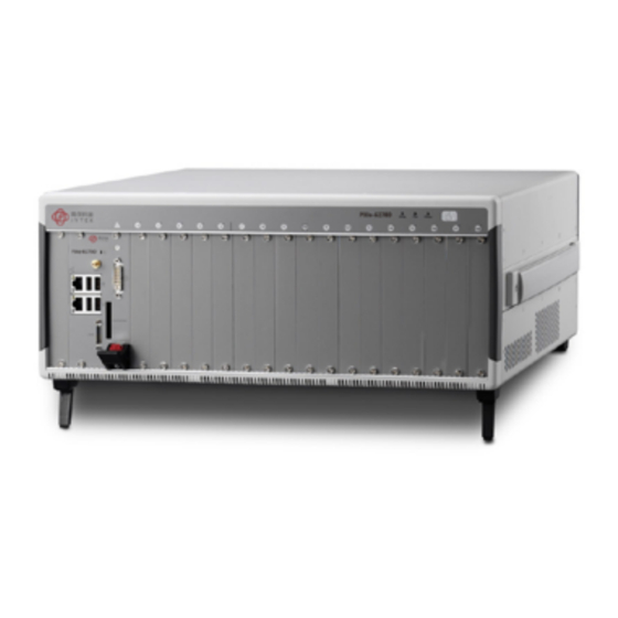
1 Introduction The JYTEK PXIe-62780 18-slot PXI Express chassis is compliant with PXI Express and cPCI Express specifications, and offers one system slot, one system timing slot, six PXIe peripheral slots, and ten hybrid peripheral slots for versatile testing and measurement applications requiring enhanced bandwidth. -
Page 7: Specifications
1�2 Specifications The PXIe-62780 complies with the PXI™-5 Specification Rev.1.0 and accepts all modules compliant with the PXI™-5, CompactPCI, and PICMG 2.0 specifications. Power Supply AC Input (*guaranteed by power supply design) Input voltage range 100 to 240 VAC Operating voltage range*... - Page 8 Cooling Fans 3 sets of 185.9 CFM fans Per-slot cooling capacity 38.2 W (verified by 55°C chamber test) Physical Slots 18 total, as follows: • 1 x system • 1 x system timing • 10 x hybrid peripheral • 6 x PXI Express peripheral Dimensions 464.3 (W) x 191.4 (H) x 465.3 (D) mm (18.1 x 7.46 x 18.14 in.)
-
Page 9: Schematics
1�3 Schematics All dimensions are shown in mm (millimeters) Figure 1-1: Front View 465.3 Figure 1-2: Right Side View... -
Page 10: Figure 1-3: Left Side View
Figure 1-3: Left Side View Figure 1-4: Rear View... -
Page 11: 1�4 Connectors, I/O, And Controls
1�4 Connectors, I/O, and Controls 1�4�1 Front Panel Figure 1-5: PXIe-62780 Front Panel Feature Details Power Powers the chassis on/off (when INHIBIT on rear panel (not shown) is set to “DEF”) Chassis Status Temperature, Fan, and Power (L to R), functions... -
Page 12: 1�4�2 Rear Panel
1�4�2 Rear Panel Figure 1-6: PXIe-62780 Rear Panel Connectors Feature Details 10MHz Reference The BNC connector acts as a 10MHz reference clock input, whereby the backplane 10MHz clock is Clock Input overridden in the presence of an external 10MHz clock... -
Page 13: Table 1-3: Rear Panel Legend
Feature Details Inhibit Switch In the DEF (default) position, the front panel power button turns the power supply on/off, and in the MAN (manual) position, the INHIBIT pin on the DB-9 connector turns the power supply on/off Fan Switch In the HIGH position, fans operate at maximum speed, and in AUTO, the fans run based on the monitored chassis temperature Universal Power Inlet... -
Page 14: 1�4�3 Backplane
1�4�3 Backplane Figure 1-8: PXIe-62780 Backplane Figure 1-9: Temperature Sensors on Backplane For details of chassis temperature detection, please see “Chassis Temperature” on page27... -
Page 15: Figure 1-10: Star Trigger Routing
PCI Express Link Capability The PXIe-62780 backplane provides a configurable PCIe switch fabric, allowing PCI express link configuration between system slot and PCIe switch fabric to change from 4-link x 4 lanes (factory default) to 2-link x 8 lanes. 4-link x 4 lanes configuration delivers the most balanced PCI express topology, with all the peripheral slots sharing equally in system bandwidth. -
Page 16: Table 1-4: Pxi Star Trigger Line Assignment
PXI-1/CompactPCI peripheral module. PXI Express Peripheral Slots 6 PXI Express peripheral slots are provided in the PXIe-62780, with 8th and 12th slots connected with PCIe x8 lanes, and the other four peripheral slots connected with PCIe x4 lanes. Each can only accommodate a 3U PXI Express/ CompactPCI Express peripheral... -
Page 17: Figure 1-11: 3U Hybrid Slot Compatible Pxi-1 Peripheral Module
Figure 1-11: 3U Hybrid Slot Compatible PXI-1 Peripheral Module Figure 1-12: 3U PXI Express Peripheral Module Local Bus The local bus on a PXI backplane is a daisy-chained bus that connects each peripheral slot with adjacent peripheral slots to the left and right. The quantity of local bus lines is... -
Page 18: Figure 1-13: Trigger Bus Bridge Capability
Trigger Bus Three trigger bus segments on the PXIe-62780 consist of a first segment from 1st to 6th slots, a second from 7th to 12th slots, and a third from 13th to 18th slots, with each trigger bus segment containing 8 trigger lines connecting all slots on the same segment, providing inter-module synchronization. -
Page 19: Table 1-5: Pxie-62780 Reference Clock Priority
Since the external 10MHz clock input can override the onboard 10MHz clock source, a phase-lock loop (PLL) circuit on the backplane synchronizes the PXIe_ CLK100 and external 10MHz clock. The PXIe-62780 PXI chassis automatically selects the 10 MHz reference clock source from among: • Built-in accurate 10 MHz clock source •... -
Page 20: Getting Started
2 Getting Started This chapter describes procedures for installing the PXIe-62780 and making preparations for its operation. Please contact JYTEK or authorized dealer if there are any problems during the installation. Diagrams and illustrated equipment are for reference only. Actual system configuration and specifications may vary. -
Page 21: Hardware Installation
2�3 Hardware Installation 2�3�1 Installing the System Controller The PXIe-62780 incorporates a system controller slot supporting a PXI Express system controller of up to 4 slot width. 1. Ensure the CPU, memory module(s), and storage device(s) are properly installed on the system controller 2. - Page 22 4. Align the module’s top and bottom edges with the cardguides, and carefully slide the module into the chassis. 5. Lift the latch until the module is securely seated in the chassis backplane 6. Fasten the screws on the module front panel, and connect all devices to the system controller.
-
Page 23: 2�3�2 Installing Peripheral Modules
2�3�2 Installing Peripheral Modules The PXE-62780 supports up to seventeen peripheral modules, including a system timing module. 1. Select an available peripheral slot (2 to 18) 2. Depress the peripheral module’s latch and align the module’s top and bottom edges with the card guides. 3. - Page 24 5. Fasten the screws on the module’s front panel. 6. Repeat steps 1 to 5 to install additional PXI or PXIe peripheral modules. To improve efficiency of heat dissipation, after installing all PXI modules, please install filler plates for any unused slots.
-
Page 25: Rack Mounting
2�4 Rack Mounting JYTEK provides hardware for optional installation of the PXIe-62780 to a rack. The kit (order name PXIe-62780 Rack Mount Kit) flexibly recesses the PXIe-62780 in the rack, accommodating external mechanical parts on the front side, such as cables and mass interconnect modules. -
Page 26: 2�4�1 Powering Up The System
2�4�1 Powering Up the System The PXIe-62780 is equipped with a 100 VAC to 240 VAC universal power supply unit requiring no input voltage selection. 1. Connect one end of the supplied power cord to thepower inlet located at the rear side of the chassis. -
Page 27: System Management & Configuration
The PXIe-62780 provides software configurable trigger bus bridges, whereby the user can set the status of each trigger bus line as shown in Figure 1-13. The PXIe-62780 backplane can also be configured between 4-link x 4 lanes or 2-link x 8 lanes by the configurable PCIe switch fabric. -
Page 28: 3�2 Monitoring The Pxie-62780
3�2 Monitoring the PXIe-62780 JYTEK provides the PXIe-62780 Chassis Remote Mon. Utility to monitor the status of the PXIe-62780. As shown, the utility is divided into three interface categories: Connect Control, Remote Status & Control, and Chassis Status. Figure 3-1: PXIe-62780 Chassis Remote Mon� Utility 3�2�1 Connect Control... -
Page 29: Figure 3-2: Log Options Dialog
Selecting Disconnect releases serial port. This section is available while Interface is set to RS232 Baud rate for RS232 is set to 9600 automatically for PXIe-62780 Chassis Status Log With the Chassis Status Log function, monitored data can be recorded. Selecting Log Chassis Status opens the Log Options dialog, as shown. -
Page 30: Chassis Control And Alarm Threshold Setting
Displays the current firmware version. 3�2�2 Chassis Control and Alarm Threshold Setting Provides operational and threshold settings for the PXIe-62780, including trigger bus, PXIe link, target temperature, and fan mode, and threshold settings for DC voltage, temperature, and cooling fan speed. -
Page 31: Figure 3-4: Target Temperature Parameters
PXIe Link Displays PCI express switch fabric settings for the PXIe-62780 backplane. Selecting required configuration (four-link x4 or two-link x8) and Config applies new settings. The new setting will not be valid until system is restarted. Target Temperature When the Fan switch on the rear panel is set to AUTO, fans run at different speeds based on the measured temperature. -
Page 32: 3�2�3 Chassis Status
Set. Fan Speed Displays Auto/Full fan speed setting status of the PXIe-62780. Auto is displayed when fans are set to auto mode and Full when the fans are set to run at full speed. Selection of Auto or Full values and selecting Set directly changes cooling fan mode. -
Page 33: Appendix A - Troubleshooting And Maintenance
Appendix A - Troubleshooting and Maintenance This Appendix describes basic troubleshooting techniques, as well as instructions for the maintenance of the PXIe-62780 chassis. A�1 Installation Problems Inability to start the system frequently results from incorrect installation of the system controller, peripheral modules, and other components. Before starting the system, please ensure that: •... -
Page 34: A�3 Maintenance
The PXIe-62780 weights 11.9 kg (26.2 lb). Please be careful when moving the chassis to avoid any possible injury. -
Page 35: Important Safety Instructions
Important Safety Instructions For user safety, please read and follow all instructions, WARNINGS, CAUTIONS, and NOTES marked in this manual and on the associated equipment before handling/operating the equipment. • Read these safety instructions carefully. • Keep this user’s manual for future reference. •...
Need help?
Do you have a question about the PXIe-62780 and is the answer not in the manual?
Questions and answers