Table of Contents
Advertisement
Quick Links
RS-232 to Fiber Optic Multiplexor
CUSTOMER
SUPPORT
INFORMATION
Order toll-free in the U.S. 24 hours, 7 A.M. Monday to midnight Friday: 877-877-BBOX
FREE technical support, 24 hours a day, 7 days a week: Call 724-746-5500 or fax 724-746-0746
Mail order: Black Box Corporation, 1000 Park Drive, Lawrence, PA 15055-1018
Web site: www.blackbox.com • E-mail: info@blackbox.com
NOVEMBER 1993
MX035A
MX035A-ST
MX035AE
MX035AE-ST
MX036A
MX036A-ST
MX036AE
MX036AE-ST
- 1 6
M U X
I B E R
3 2 F
R S - 2
E R
P O W
D
S D C
Advertisement
Table of Contents

Subscribe to Our Youtube Channel
Related Manuals for Black Box MX035A


Summary of Contents for Black Box MX035A
- Page 1 Order toll-free in the U.S. 24 hours, 7 A.M. Monday to midnight Friday: 877-877-BBOX FREE technical support, 24 hours a day, 7 days a week: Call 724-746-5500 or fax 724-746-0746 SUPPORT Mail order: Black Box Corporation, 1000 Park Drive, Lawrence, PA 15055-1018 INFORMATION Web site: www.blackbox.com • E-mail: info@blackbox.com...
- Page 2 FCC/IC STATEMENTS AND TRADEMARKS FEDERAL COMMUNICATIONS COMMISSION INDUSTRY CANADA RADIO FREQUENCY INTERFERENCE STATEMENTS This equipment generates, uses, and can radiate radio frequency energy and if not installed and used properly, that is, in strict accordance with the manufacturer’s instructions, may cause interference to radio communication. It has been tested and found to comply with the limits for a Class A computing device in accordance with the specifications in Subpart J of Part 15 of FCC rules, which are designed to provide reasonable protection...
-
Page 3: Table Of Contents
5.1 General ....................18 5.2 Troubleshooting Procedure ............. 18 5.3 Testing ....................19 5.4 No Data Transfer on All Channels ..........23 5.5 Data Transfer Is Badly Corrupted ............ 25 5.6 Calling BLACK BOX ................. 26 5.7 Shipping and Packaging ..............26... -
Page 4: Specifications
CHAPTER 1: Specifications 1. Specifications Approvals — FCC Class A, IC Class/classe A Multiplexing Technique — Time-division User Channels — MX035 units: (8); (24) in Triple Asynchronous Mode with 3-to-1 adapter cable (EYN355) MX036 units: (16); (48) in Triple Asynchronous Mode with 3-to-1 adapter cable (EYN355) Interface —... - Page 5 MX035AE, MX036AE units: Directly from outlet: Input range: 230 VAC, 50 to 60 Hz, 0.5 A Fuse — MX035A, MX036A units: 1 A, 120-VAC Slo-Blo; MX035AE, MX036AE units: 0.5 A, 220-VAC Slo-Blo Temperature — 32 to 113˚ F (0 to 45˚ C) ambient Humidity —...
-
Page 6: Introduction
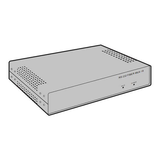
CHAPTER 2: Introduction 2. Introduction 2.1 General The RS-232 to Fiber Optic Multiplexor is available in two major model types: one with 8 channels (product codes beginning with “MX035”), and one with 16 channels (product codes beginning with “MX036”). Both models are built from the same circuit board and are identical in every way except for the number of channels. -
Page 7: Physical Description
RS-232 TO FIBER OPTIC MULTIPLEXOR 5. The fifth mode is synchronous with external clocking (the terminal device supplies the clock to the multiplexor). Like all other modes but the third, this mode supports DTR/CTS handshaking. The mux will accept and adapt to any externally-clocked data rate up to 14,400 bps. - Page 8 CHAPTER 2: Introduction Figure 2-2. The rear panel. 2. Optical-Receiver Connector: SMA or ST compatible connector for the optical receiver. 3. Switch-Setting Chart: Identifies the channel-configuration-switch settings. 4. Channel-Configuration Switches: A 6-position DIP switch for each channel, which you can use to select the internal transmit clock/data rate, or secondary transmit data in place of the transmit clock.
-
Page 9: Installation
RS-232 TO FIBER OPTIC MULTIPLEXOR 3. Installation This section describes the installation procedures for the multiplexor in a standard 19-inch rack and explains how to connect the optical cable and the terminal devices. If possible, test the pair of multiplexors and the optical cable with each other before installation. - Page 10 CHAPTER 3: Installation Figure 3-1. Attaching a rackmount bracket. I P L After removing the screws, place one of the rackmount brackets against the side of the multiplexor, lining up the four round holes in the long side of the bracket with the holes from which the screws were just removed.
-
Page 11: Ac Power Connection
RS-232 TO FIBER OPTIC MULTIPLEXOR 3.2 AC Power Connection The 120-VAC version of the multiplexor requires 95 to 130 VAC, 50 to 60 Hz power, at a maximum current of 1 ampere. It is equipped with a U.S.-standard three-prong power plug that should be connected to a properly grounded AC outlet. -
Page 12: Channel-Cable Connection
CHAPTER 3: Installation Figure 3-2. Connecting fiberoptic cables. OPTICAL MULTIPLEXOR FIBER OPTIC CABLE Take care in the placement of the optical cables to ensure that the cables are not subjected to stress at or near the optical connectors. Take special caution to ensure that there are no sharp bends in the cable near the connectors. -
Page 13: Configuration And Operation
RS-232 TO FIBER OPTIC MULTIPLEXOR 4. Configuration and Operation This chapter describes how to configure each channel for the desired mode of operation and how to operate the multiplexor. 4.1 Modes of Operation On each channel of the multiplexor, one of five modes of operation can be independently selected: 1. - Page 14 CHAPTER 4: Configuration and Operation Figure 4-1. DIP-Switch settings. 19.2K 4.8K 1.2K All positions OFF: Asynchronous, one control signal (Mode 1). 9.6K 2.4K “STD”: (a) Asynchronous, control and auxiliary signals (Mode 2); (b) triple asynchronous, no control signals (Mode 3); or DIP SWITCH (c) synchronous, external clock received on Pin 14 (Mode 5).
- Page 15 RS-232 TO FIBER OPTIC MULTIPLEXOR Signals fed into the A connector at one end of the system (attached to a terminal device connected to one mux) will be received at the A connector at the other end of the system (attached to a terminal device connected to the other mux), and vice versa.
-
Page 16: Operating The Multiplexors
CHAPTER 4: Configuration and Operation The mux can accept and adapt to any data rate up to 14,400 bps on a channel in this mode. To set a given channel for this mode, set that channel’s STD switch position ON, all others OFF. NOTE Any time the mux’s STD switch position is ON (Mode 2, 3, or 5), the signal input to the mux on Pin 14 will be retransmitted back out Pin 15. - Page 17 RS-232 TO FIBER OPTIC MULTIPLEXOR This sampling and reconstruction induces variable propagation delays on each signal, since signals coming into the mux from external sources will not necessarily be synchronized to the internal sampling clock. Maximum timing distortion is 13.2 µs, which is 1/4 of one bit time at the maximum input data rate of 19.2 Kbps.
- Page 18 CHAPTER 4: Configuration and Operation Data Terminal Ready (DTR, Pin 20) and Clear to Send (CTS, Pin 5) The signal fed into the Data Terminal Ready input (Pin 20) of a multiplexor channel is transmitted to the other multiplexor, where it appears at the Clear to Send output (Pin 5).
- Page 19 RS-232 TO FIBER OPTIC MULTIPLEXOR Table 4-1. Signal Paths (Per Channel) Each signal’s originating device(s) are shown by the letter “O.” Each signal’s destination device(s) are shown by the letter “D.” Positive voltage is shown by “+V.” Signal directions are shown by arrows. Channel is in Mode 1 (Async, 1 Control): Signal Local...
- Page 20 CHAPTER 4: Operation 4.3.3 C ONNECTING HREE SYNCHRONOUS INES TO ULTIPLEXOR HANNEL As described in Section 4.1.3, three separate asynchronous data-only channels (no control signals) can be transmitted through one channel of the multiplexor. To connect three standard RS-232 cables to one multiplexor channel requires an adapter cable (product code EYN355).
-
Page 21: Troubleshooting
RS-232 TO FIBER OPTIC MULTIPLEXOR 5. Troubleshooting 5.1 General All circuitry of the multiplexor is on a single printed circuit board. Troubleshooting by the user is limited to isolating a failure to either one of the multiplexors or the fiberoptic cable. 5.2 Troubleshooting Procedure 1. -
Page 22: Testing
CHAPTER 5: Troubleshooting 6. There is a possibility of other problems with the Clear to Send signal. Clear to Send at one end of the system is true only if Data Terminal Ready is true at the other end of the system; therefore, problems might occur if a terminal device that requires Clear to Send attempts to communicate through the multiplexor with a terminal device that does not provide the Data Terminal Ready signal. - Page 23 RS-232 TO FIBER OPTIC MULTIPLEXOR In addition to end-to-end tests with either BERTs or breakout boxes, local or remote loopback tests can be performed using the procedures in Sections 5.3.2 and 5.3.3. Other than the method of performing the actual loopback, the only difference between loopback testing and end-to-end testing is that with loopback tests, input fed into one multiplexor causes an output change at the same multiplexor, rather than at the other end of the system (as in end-to-end...
- Page 24 CHAPTER 5: Troubleshooting verify the waveform with an oscilloscope at both the transmitting and receiving ends. (At the receiving end, there will be varying timing distortion— that is, jitter—of up to 13 µs, caused by the sampling rate of the multiplexing circuits.) Connect the internal transmit clock from Pin 15 at one multiplexer to the Transmit Data input (Pin 2) and verify that the same signal appears at the Receive Data output (Pin 3) of the other multiplexor.
-
Page 25: No Data Transfer On All Channels
RS-232 TO FIBER OPTIC MULTIPLEXOR 5.3.3 L OCAL OOPBACK ESTING If the remote loop test shows one or more channels of the multiplexor system not operating or generating data errors, the problem can be isolated to one multiplexor by a local loop test. A local loop test is performed by connecting the optical transmitter of the multiplexor back to its own optical receiver, which causes all signals fed into any channel of the multiplexor to be looped back to the corresponding... - Page 26 CHAPTER 5: Troubleshooting fiberoptic cable or one of the multiplexors. First, check the muxes’ switch settings and their RS-232 connectors. If these are OK, check the fiberoptic cable’s connectors and the muxes’ optical transmitters and receivers for fingerprints and other things that could impede or distort optical signals. If you find anything, clean the affected surface with an alcohol-saturated cotton swab.
- Page 27 RS-232 TO FIBER OPTIC MULTIPLEXOR CAUTION! Do not look into the transmitter. Prolonged exposure to high-intensity infrared light will cause eye damage. 3. If both optical transmitters appear to be operating and only one SDCD LED is OFF, reverse the fiberoptic cable connections at both ends of the cable.
-
Page 28: Data Transfer Is Badly Corrupted
CHAPTER 5: Troubleshooting 5.5 Data Transfer Is Badly Corrupted If data transfer in one or both directions has high error rates, the problem is most likely inadequate optical signal strength, caused by either (a) foreign matter in a fiberoptic interface, (b) low optical power output of one or both optical transmitters, (c) inadequate sensitivity of one or both optical receivers, or (d) damage to the fiberoptic cable resulting in excessive optical-signal attenuation. -
Page 29: Calling Black Box
RS-232 TO FIBER OPTIC MULTIPLEXOR 5.6 Calling Us If you determine that your multiplexor itself is malfunctioning, do not attempt to alter or repair the unit. Contact us; the problem may be solvable over the phone. Before you do, make a record of the history of the problem. We will be able to provide more efficient and accurate assistance if you have a complete description, including: •... - Page 30 © Copyright 1993. Black Box Corporation. All rights reserved. 1000 Park Drive • Lawrence, PA 15055-1018 • 724-746-5500 • Fax 724-746-0746...
Need help?
Do you have a question about the MX035A and is the answer not in the manual?
Questions and answers