Table of Contents
Advertisement
Quick Links
Advertisement
Chapters
Table of Contents

Related Manuals for Pellas X M-line M350

Summary of Contents for Pellas X M-line M350
-
Page 5: Table Of Contents
TABLE OF CONTENTS 1. GENERAL INFORMATION ................3 1.1. Transportation ................... 3 1.2. Storage .................... 3 1.3. Control of burner’s delivery ..............4 1.4. Free space around burner ..............4 2. PRODUCT DESCRIPTION ................4 2.1. Construction of M350 and M500 burners..........5 2.2. - Page 6 7. SERVICE OF DEVICES ................23 7.1. Photosensor ..................23 7.2. Electrical igniter replacement ............. 24 7.3. Feeder pipe cleaning ................. 24 7.4. Burner cleaning ................24 8. TROUBLESHOOTING 25 9. ELECTRICAL SCHEMES ................26 9.1. Electrical scheme of PellasX controller ..........26 9.2.
-
Page 7: General Information
1. GENERAL INFORMATION Read carefully the user’s manual before activating burner. PellasX burner requires installation according to this user’s manual. Following advice included in this USER’S MANUAL will guarantee safe functioning and installation of the device. All doubts and ambiguities as to condition of equipment or given functions of parts of burner should be reported to the seller in order to get explanations. -
Page 8: Control Of Burner's Delivery
1.3. Control of burner’s delivery Before commencing assembly activities check the following: condition of packaging, make sure that there are no visible damages and if delivery is complete and not damaged. Possible reservations and problems should be reported to the supplier immediately. He is responsible for insuring the merchandise. -
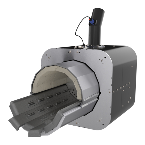
Page 9: Construction Of M350 And M500 Burners
The unique solutions employed in the M line burners include: • Mesh Furnace System – the system of modular heat-resistant plates forming the furnace ensures the self-cleaning process through the reciprocating movement of the grate. It is possible to adjust the stroke depending on the type of fuel burned; •... -
Page 10: Quality Requirements For Pellets Fuel
2.2. Quality requirements for pellets fuel In table below given requirements as to quality of pellet fuel are shown. Using fuel which complies to DIN 51731 or DIN PLUS certification or meet the rules of EN-14961-2 norm, extends longevity of burner. The pellet storage location should be dry and well-ventilated. It is important that prior to the hopper filling the pellet temperature is equal to the boiler room temperature. -
Page 11: Technical Data
Pic. 2. Burner nameplate template. 2.4. Technical data Main properties of PellasX burners from M-line: Safety • Overpressure Combustion System – flashback protection; • Burner temperature sensor; • Polyurethane pellet feeding pipe – melts in case of flashback, cutting the fuel supply. Reliability •... - Page 12 Type M350 M500 Heating power 65 - 350 kW 75 - 500 kW Power supply 230 V AC / 50Hz 230 V AC / 50Hz Average power consumption 350 W 350 W Weight 170 kg 200 kg Noise emission 73 dB 73 dB Feeder’s length pellet 6-8 mm...
-
Page 13: Pic. 3. Dimensions Of M350 Burner
Pic. 3. Dimensions of M350 burner. Pic. 4. Dimensions of M500 burner. -
Page 14: Safety Systems
2.5. Safety systems PellasX burner is equipped with following safety systems, which effectively protect the user against flashback of fire: 1. Burner temperature sensor The sensor, once it detects temperature over 90°C (setting: alarm temperatures may be modified depending on the conditions in which the device operates i.e. bakery ovens or dryers;... -
Page 15: Installation
3. INSTALLATION 3.1. Chimney The parameters of chimney should be adjusted to requirements of heating device, of which fumes are led away to chimney. The chimney can be made of ceramics or steel. Chimney should be clean, and its draft sufficient for PellasX burner operating with heating device in scope of preset power output. -
Page 16: Pic. 6. Fixing Of Burner In The Boiler
Fix the burner with M10 screws (length of the screw depends on boiler wall thickness) Pic. 6. Fixing of burner in the boiler. Pic. 7. Positioning of burner and direction of flame. - Page 17 Table 4. Minimum dimensions of furnace chamber. MINIMUM DIMENSIONS OF FURNACE CHAMBER TYPE OF BURNER MINIMUM DIMENSIONS MINIMUM LENGHT FURNACE CHAMBER [m FURNACE CHAMBER [mm] M350 0,313 1400 M500 0,450 1500 Tabele 5. Exemplary minimum dimensions of rectangular furnace chamber. EXEMPLARY MINIMUM DIMENSIONS OF RECTANGULAR FURNACE CHAMBER TYPE OF BURNER...
-
Page 18: Fuel Hopper
3.3. Fuel hopper Fuel hopper can be made of any non-flammable material, i.e. steel. It can have any capacity and should be located in proper distance from burner (Pic.10). In lower part of fuel hopper a spiral feeder in covering pipe is mounted. The slope of feeder should not be bigger than 45° in relation to the floor. -
Page 19: Stb Protection
3. Put the shaft (9) in the motorgear opening (6). Secure the shaft with M8 screw with washers (14) 4. Slide the spiral to the pipe. Mount the motorgear (6) on the pipe flange using M10x85 screws (11) and M10 nuts with the washers (12); ATTENTION: The spiral should end in the middle of opening in the feeder (pic. -
Page 20: Burner And Feeder Assembly
4. BURNER AND FEEDER ASSEMBLY Pic. 10. Scheme of installation in boiler room. Burner and feeder are delivered in ready-made state, ready for installing. They are packed in cardboard boxes, which have to be unpacked with care. ATTENTION! Before starting dismantling or disassembly entire power supply must be disconnected. -
Page 21: Connecting The Feeder
Pic. 11. Installation of burner. Pic. 12. Lifting eye. 4.2. Connecting the feeder • Attach with joint flexible pouring pipe, long enough to connect with upper part of the feeder, no less however than 30 cm from vertical pouring axis of burner. Second part of flexible pipe insert onto vertical pipe of chimney for pouring fuel of burner and tighten it with a band. -
Page 22: Additional Connections And First Startup
5. ADDITIONAL CONNECTIONS AND FIRST STARTUP • Additional connections of the burner are described in the controller manual. • Determination of the supplied pellet capacity: 1. Before starting the balancing procedure, make sure that the feeder is filled with pellets. 2. - Page 23 Step 1 Step 2 Find highlighted element Take out highlighted plates Step 4 Step 3 While keeping the plate pulled, take out plate Pull highlighted element marked in red. Step 5 Step 6 Release the element from step 3 Repeate steps 3-5 for remaining rows...
- Page 24 Step 7 Step 8 Make sure that highlighted elements will not Take out side plates marked in red be removed Step 9 Step 10 Take out central plates marked in red Clean the space under the grate Step 11 Step 12 Mount back highlighted elements Mount back highlighted elements...
-
Page 25: Specification Of The Inspection Intervals
Step 14 Step 13 Check if the plates are fitted well and create Mount back highlighted elements uniform surface Pic. 13. M350/M500 grate dismounting and mounting. ATTENTION! After burning off, furnace can still be hot. That is why you should always use tools, i.e. -
Page 26: Scope Of Operational Activities
6.4. Scope of operational activities • For basic operation inspection: Check of setting of the automatic; Check of safety devices (STB, boiler and burner temperature sensors); Check and cleaning of the flame sensor; Fumes analysis and chimney draught measuring; Record of service counters status; Cleaning of the blowing nozzles and burner furnace;... -
Page 27: Guarantee
Failure in observing by the user – owner of a burner the above SAFETY REGULATIONS releases Manufacturer – PELLASX sp. z o.o. sp. k. from any responsibility for improper work of a burner and results in loss of the warranty. If the user executes the installation of a burner not in accordance with instructions and recommendations of the producer or when he does not have the „Collection Report”... -
Page 28: Electrical Igniter Replacement
7.2. Electrical igniter replacement M350/M500 burners are equipped with two igniters. When either one of them does not heat even though the “firing up” message is shown, it is probably damaged. For replacing the igniter, remove the back cover and a revision plate on the side of burner. Disconnect damaged igniter in X-Sync controller module. -
Page 29: Troubleshooting
8. TROUBLESHOOTING 1. Burner does not fire up the fuel: Reasons: • No fuel – check the fuel hopper and the feeder, if it is not blocked; • Too small startup dose – check the startup dose; • Burnt igniter – check the igniter; •... -
Page 30: Electrical Schemes
9. ELECTRICAL SCHEMES 9.1. Electrical scheme of PellasX controller See controller’s user manual 9.2. Electrical scheme of M350 / M500 burners Pic. 16. Electrical scheme of M350/M500 burner. -
Page 31: Reports
10. REPORTS 10.1. First start-up report Table 9. First start-up report template. -
Page 32: Inspection Report
10.2. Inspection report Table 10. First inspection report template. -
Page 33: List Of Pictures And Tables
11. LIST OF PICTURES AND TABLES Pictures list: Pic. 1. Construction of M350 and M500 burners..............6 Pic. 2. Burner nameplate template..................8 Pic. 3. Dimensions of M350 burner..................10 Pic. 4. Dimensions of M500 burner..................10 Pic. -
Page 34: Notes
12. NOTES... - Page 35 NOTES...
Need help?
Do you have a question about the M-line M350 and is the answer not in the manual?
Questions and answers