Advertisement
Quick Links
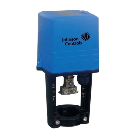
VAP Series balancing valve actuator -Installation Instructions
VAP系列平衡阀执行器 -安装说明
基本参数
Basic Parameter
型号
VAP500-24-C
Model
额定输出力
500N
Rating Force
电源
24V AC
Power Supply
控制类型
比例调节型
Type of Control
proportional
功率消耗
7.5VA
Power Consumption
最大行程
22mm
Max. Stroke
运行速度
3.85s/mm(50Hz)
Running Speed
产品净重
1.7Kg
Net Weight of Product
双向灵敏度
高灵敏度≤1.0%;低灵敏度≤1.5%
Sensitivity
机壳防护等级
IP54
Enclosure Rating
Wiring Diagram
接线图
调试说明
A. 安装执行器及阀门(具体操作见安装说明)。
B. 关闭执行器电源开关(VAP3000-24-C电源开关在执行器底板后侧下方位置,
VAP500-24-C/VAP1000-24-C无电源开关)。
C. 接线完毕(见接线说明)。
D. 将拨码开关设定到需要的位置(拨码开关可带电设置)。
E. 打开执行器电源开关。
F. 自适应(出厂默认为上电自适应):此步骤的目的为使执行器与阀体进行行程匹配:
1) 打开执行器电源,执行器自动进入自适应状态。
2) 运行指示灯(RUN)闪烁(频率约为1Hz),执行器轴先伸出运行至下极限,然
后在缩进运行至上极限。(此时执行器将不受控制信号的控制)
3) 约3分钟后指示灯停止闪烁,此时执行器与阀体的自适应结束,阀体与执行器的
配合调节完成。此时执行器的运行方向由控制信号控制
G. 开度调节:通过调节开度电位器实现阀门最大开度在100%至30%范围内连续调节,
灵活的调节阀体内的相对流量与其开度间关系: 100%-40%开度区间内均分为高
低灵敏度,40%-30%开度区间内均为低灵敏度。
注明:1. 当执行器在通电情况下,若需自适应,按下执行器电路板上的红色按键3s以上,执行器进入
自适应状态。自适应现象与(2)(3)现象相同。
2. 如需更改自适应模式,可通过调节第七位拨码进行自适应模式选择设定,见拨码开关设定说明。
601U-B01A-NC-Issue Date 11 2013
601U-B01A-NC-Issue Date 11 2013
VAP500-24-C
用于VPA系列DN25-50平衡阀
For VPA Series Balancing Valve DN25-50
VAP1000-24-C
VAP3000-24-C
1000N
3000N
15VA
43mm
3.2s/mm(50Hz)
5.2Kg
高灵敏度≤1.5%;低灵敏度≤2.0%
This document is subject to change without notice 本文档如有变化,恕不另行通知
VAP1000-24-C
用于VPA系列DN50/65平衡阀
For VPA Series Balancing Valve DN50/65
型号
Model
控制信号
Control Signal
阀位反馈信号
Feedback Signal
电压输入阻抗
Voltage Input Impedance
电流输入阻抗
Current Input Impedance
电压输出负载要求
Voltage Output Load
电流输出负载要求
Current Output Load
上下极限死区范围
Up and Down Dead Band
环境湿度
Ambient Humidity
环境温度
Ambient Temperature
接线端子Terminal
B,O
O
E
Y
Wiring Diagram
A. Assemble the actuator with valve body. ( Please refer to installation instructions)
B. Turn off the power switch of actuator.(Power switch is under the right side of VAP3000-24-C
actuator, no power switch for VAP500-24-C/VAP1000-24-C)
C. Finish the wiring. (Please refer to wiring diagram)
D. Set DIP switches as required. (DIP switches can be set when power on)
E. Turn on the power switch of actuator.
F. Self-stroking. (Factory setting: self-stroking starts automatically when power on each time) :
The purpose of this step is to make the actuator matching with the stroke of the valve body.
1) Turn on the power switch, self-stroking starts automatically.
2) Running light (RUN) flickers (frequency 1Hz. Actuator axes extends until down limit position,
then retracts to up limit position. This moment, actuator can not be controlled by control
signal.)
3) Running light (RUN) stops flickering after appr. 3 minutes when self-stroking finish. Now
actuator matches the stroke of the valve body. Actuator can be controlled by control signal.
G. Aperture regulating. Biggest stroke of the valve can be adjusted from 30%~100% of its original
stroke by regulating the aperture potentiometer. Flow rate can be regulated neatly.(40%~30%,
only low sensitivity of control signal. 100%~40% high and low sensitivity selectable.)
Remarks:1. When power on, self-stroking can also be operated manually by pressing the red self-
stroking button on PCB for over 3 seconds. Self-stroking cycle repeats as step 2) & 3).
2. If you want to change self-stroking mode, adjust the seventh DIP switch. (Please refer to
DIP switch setting)
VAP3000-24-C
用于VPA系列DN80-150平衡阀
For VPA Series Balancing Valve DN80-150
VAP500-24-C/VAP1000-24-C/VAP3000-24-C
0(2)~10VDC, 0(4)~20mA
0(2)~10VDC,0(4)~20mA
>100K
<0.167K
>1K
<0.5K
≤2.5%
≤95% RH(40℃)
-10℃~50℃
24VAC电源/ 24VAC Power supply
控制信号/反馈信号公共端COM for control/feedback signal
控制信号Control signal
反馈信号Feedback signal
1
Advertisement

Related Manuals for Johnson Controls VAP Series


Summary of Contents for Johnson Controls VAP Series
- Page 1 VAP Series balancing valve actuator -Installation Instructions VAP系列平衡阀执行器 -安装说明 VAP500-24-C VAP1000-24-C VAP3000-24-C 用于VPA系列DN25-50平衡阀 用于VPA系列DN50/65平衡阀 用于VPA系列DN80-150平衡阀 For VPA Series Balancing Valve DN25-50 For VPA Series Balancing Valve DN50/65 For VPA Series Balancing Valve DN80-150 基本参数 Basic Parameter 型号 型号 VAP500-24-C VAP1000-24-C...
- Page 2 VAP Series balancing valve actuator -Installation Instructions VAP系列平衡阀执行器 -安装说明 S2、S3拨码开关设定 S2, S3 DIP Switch Setting 拨码 功能 设定值功能描述 Function Description 20%: 控制/阀位反馈信号起始点为20%(适用于控制/阀位反馈信号为4~20mA或2~10VDC) 控制/阀位反馈信号起始点 20%: The starting control / feedback signal is 20% (namely 4~20mA or 2~10VDC) 设定 Starting of control / 0: 控制/阀位反馈信号起始点为0(适用于控制/阀位反馈信号为0~20mA或0~10VDC)(出厂默认设定)
- Page 3 VAP Series balancing valve actuator -Installation Instructions VAP系列平衡阀执行器 -安装说明 2)数码管数字位,包括3为数码管,其最小显示值为0,最大显示值为100,显示精 2) Numerical bit of LED ( displayed value: Min.1, Max.100, precision ±1) 度为±1 3) When actuator is running correctly, it shows "C" or "F" alternately in the LED, it 3)当执行器正常运行时,数码管在C和F直接交替显示,即输入信号与执行器反馈信...
- Page 4 VAP Series balancing valve actuator -Installation Instructions VAP系列平衡阀执行器 -安装说明 安装说明 Installation 先取下滑块,驱动器夹子松开,做好装配准备。 使驱动器主轴与阀杆同心,并且端面重合;将驱动 将滑块装入驱动器凹槽内,用两个螺丝锁紧。 正面装配完成后状态。 器置于阀体凸台上,锁紧夹子上的两个螺丝。 Prepare for assembling the actuator, take Pull the fixed fitting to the groove and lock The status after assembled. Keep the actuator’s axes and the valve’s down the fixed fitting firstly, and then by two screws.
Need help?
Do you have a question about the VAP Series and is the answer not in the manual?
Questions and answers