Advertisement
Table of Contents
- 1 Special Tools Needed
- 2 Mounting the Actuator to Spring Return Port a (Coil) Open
- 3 Mounting the Actuator to Spring Return Port a (Coil) Closed
- 4 Mounting the Thermal Barrier
- 5 Manual Override
- 6 Using Conduit
- 7 Setup and Adjustments
- 8 Mode Selection Switch
- 9 Control Response
- 10 Calibration (CAL) Function
- 11 Auxiliary Switch (VA9208-XXC-3 Models)
- 12 Repair Information
- 13 Technical Specifications
- 14 VA9208-Ggx-X Series Proportional Electric Spring Return Actuator (Part 1 of 2 )
- Download this manual
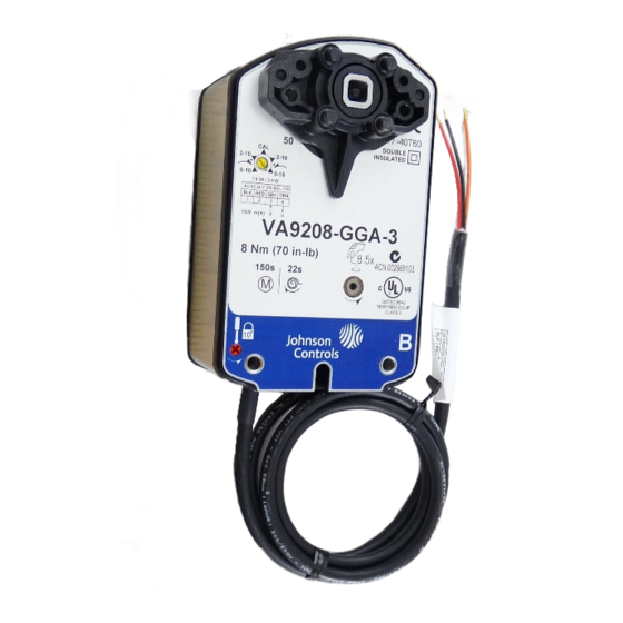
VA9208-GGx-x Series Proportional Electric Spring Return
Valve Actuators
Installation Instructions
VA9208-GGA-3, VA9208-GGC-3
VA9208-GGA-2
Applications
The VA9208-GGx-x Series Proportional Electric Spring
Return Actuators are direct-mount valve actuators that
operate on AC/DC 24 V power. These bidirectional
actuators are used to provide accurate positioning on
Johnson Controls® VG1000 Series 1-1/4, 1-1/2, and
2 in. (DN32, DN40, and DN50), ball valves in Heating,
Ventilating, and Air Conditioning (HVAC) applications.
Integral line voltage auxiliary switches, available only
on the VA9208-xxC-3 models, indicate end-stop
position, or perform switching functions within the
selected rotation range.
VA9208-GGA-2 actuators include plenum-rated cables
and are specially configured for installation in spaces
used for environmental air-handling purposes other
than ducts and plenums as specified in National Fire
Protection Association (NFPA) 70: National Electrical
Code section 300.22(C), Other Space Used for
Environmental Air. The space over a hung ceiling used
for environmental air handling purposes is an example
of the type of space for which these actuators are
configured.
VA9208-GGx-x Series Proportional Electric Spring Return Valve Actuators Installation
Refer to the
QuickLIT website
IMPORTANT: Use this VA9208-GGx-x Series
Proportional Electric Spring Return Actuator only to
control equipment under normal operating
conditions. Where failure or malfunction of the
electric actuator could lead to personal injury or
property damage to the controlled equipment or
other property, additional precautions must be
designed into the control system. Incorporate and
maintain other devices, such as supervisory or
alarm systems or safety or limit controls, intended to
warn of or protect against failure or malfunction of
the electric actuator.
IMPORTANT : Utiliser ce VA9208-GGx-x Series
Proportional Electric Spring Return Actuator
uniquement pour commander des équipements
dans des conditions normales de fonctionnement.
Lorsqu'une défaillance ou un dysfonctionnement du
electric actuator risque de provoquer des blessures
ou d'endommager l'équipement contrôlé ou un autre
équipement, la conception du système de contrôle
doit intégrer des dispositifs de protection
supplémentaires. Veiller dans ce cas à intégrer de
façon permanente d'autres dispositifs, tels que des
systèmes de supervision ou d'alarme, ou des
dispositifs de sécurité ou de limitation, ayant une
fonction d'avertissement ou de protection en cas de
défaillance ou de dysfonctionnement du electric
actuator.
Installation
Install the ball valve with the actuator at or above the
center line of the horizontal piping (see Figure 1).
IMPORTANT: In steam applications, install the
valve with the stem horizontal to the piping. Failure
to follow this precaution may shorten the life of the
actuator.
14- 1379- 21, Rev . F
Part No. 14-1379-21, Rev. F
Release June 2018
for the most up-to-date version of this document.
Instructions
1
Advertisement
Table of Contents


Need help?
Do you have a question about the VA9208-GG Series and is the answer not in the manual?
Questions and answers