
Related Manuals for BioSmart BioSmart PalmJet

Summary of Contents for BioSmart BioSmart PalmJet
- Page 1 BioSmart BioSmart PalmJet, BioSmart PalmJet BOX, BioSmart PalmJet BOX-T Reader Operation Manual Version 049.1 Date 03.2021...
-
Page 2: Table Of Contents
Electromagnetic Fields and Electric Current .......................... 10 Additional Restrictions .................................... 11 Installation ..........................................12 BioSmart PlamJet Reader Installation ............................12 Installation of BioSmart PalmJet BOX reader (BioSmart PalmJet BOX-T) ............13 Reader Connection ......................................15 Wire Assignment ....................................... 15 Power Supply Connection ................................... 15 Ethernet Connection .................................... - Page 3 Servicing ..........................................35 General Information ....................................35 Protective Measures ....................................35 Maintenance for Intended Usage ..............................35 Maintenance in Storage ..................................35 Storage and Transportation ..................................37 Utilization ..........................................37 Appendices ............................................ 38 BioSmart PalmJet, BioSmart PalmJet BOX, Operation Manual BioSmart BioSmart PalmJet BOX-T v.049.1|03.2021|en...
-
Page 4: Introduction
Thank you for purchasing our product. Subject to the rules of installation and operation, this device will serve for many years. Introduction This operating manual (OM) applies to the BioSmart PalmJet, BioSmart PalmJet BOX, BioSmart PalmJet BOX-T readers (hereinafter referred to as “readers”), the procedure for installation, connection, use and configuration. -
Page 5: The Reader Description
RFID-tag codes with subsequent transfer of the read information to the BioSmart UniPass Pro controller or to a computer with BioSmart SmartHub installed. BioSmart PalmJet reader is designed to build into a wall or turnstile. It’s located into a hole with 72 mm diameter and 45 mm depth. -
Page 6: Composition And Appearance
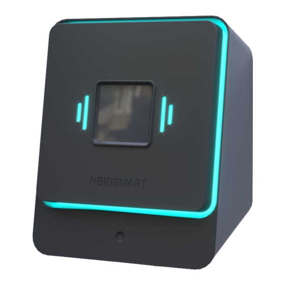
Composition and Appearance The reader appearance depends on its model. BioSmart PalmJet reader has a built-in design and is shown in Figure 1. Figure 1 – BioSmart PalmJet reader BioSmart PalmJet BOX (BioSmart PalmJet BOX-T) reader is designed for surface mounting. The appearance is shown in Figure 2. -
Page 7: Construction And Work
The read biometric data is transferred to the BioSmart UniPass Pro controller or to a computer with the BioSmart SmartHub software service. Next, the obtained biometric data is compared with the palm vein patterns stored in the database. - Page 8 For example, BioSmart UniPass Pro or BioSmart SmartHub activates the relay and controls the indication on the reader. If no match is found or the access settings prescribe to deny passage, then BioSmart UniPass Pro or BioSmart SmartHub performs other actions specified in the working model. For example, BioSmart UniPass Pro or BioSmart SmartHub controls the sound signal on the reader.
-
Page 9: Marking And Sealing
The parameters of the indication operation mode is explained by example of the action "An image is received from BioSmart PalmJet". The above settings mean the following: Green signal 20 * 100 ms – the 20 times signal repetition with a duration of 100 ms;... -
Page 10: Operating Restrictions
BioSmart PalmJet BOX and BioSmart PalmJet BOX-T readers operation when exposed to atmospheric precipitation or other liquids is not allowed. The cases of these readers (in contrast to the BioSmart PalmJet reader) are not protected against dust and moisture penetration into the case, which may lead to the readers failure;... -
Page 11: Additional Restrictions
When using the built-in temperature sensor of the BioSmart PalmJet BOX-T reader and to minimize the temperature measurement error, it’s necessary to exclude the cold air flows influence (for example, from outside or an air conditioner) or hot air flows to the reader, as well as the influence of various heaters and hot appliances. -
Page 12: Installation
The section contains the readers installation procedure and hardware kit. The mounting method for BioSmart PalmJet and BioSmart PalmJet BOX (BioSmart PalmJet BOX-T) readers is different. Section 3.1 describes the installation procedure the BioSmart PalmJet reader, section 3.2 describes the installation procedure the BioSmart PalmJet BOX (BioSmart PalmJet BOX-T) reader. -
Page 13: Installation Of Biosmart Palmjet Box Reader (Biosmart Palmjet Box-T)
Readers are supplied with a mounting plate for vertical or horizontal surfaces, depending on the operation way. Figure 5 shows a diagram of installing the BioSmart PalmJet BOX reader (BioSmart PalmJet BOX-T) on a vertical surface. Figure 6 shows a diagram of the BioSmart PalmJet BOX (BioSmart PalmJet BOX-T) reader installation on a horizontal surface. - Page 14 Page 14 of 39 Figure 5 – Installation scheme of BioSmart PalmJet BOX reader (BioSmart PalmJet BOX-T) on a vertical surface Figure 6 – Installation scheme of BioSmart PalmJet BOX reader (BioSmart PalmJet BOX-T) on a horizontal surface BioSmart PalmJet, BioSmart PalmJet BOX,...
-
Page 15: Reader Connection
Figure 7 – Power supply connection scheme Ethernet Connection To connect to an Ethernet network, connect the Ethernet cable into the network device. The scheme is shown in Figure 8. BioSmart PalmJet, BioSmart PalmJet BOX, Operation Manual BioSmart BioSmart PalmJet BOX-T v.049.1|03.2021|en... -
Page 16: Electromechanical Lock Connection
It is forbidden to use a common power supply for connecting the lock and reader. If it’s necessary to control one electromechanical lock using two readers, the connection is carried out in accordance with the scheme below (Figure 10). BioSmart PalmJet, BioSmart PalmJet BOX, Operation Manual BioSmart BioSmart PalmJet BOX-T... -
Page 17: Buttons And Sensors To A Discrete Input Connection
The current flowing through the load and the digital output mustn’t exceed 50 mA. When a voltage of 12 V is supplied, the load resistance must be at least 250 Ohm. BioSmart PalmJet, BioSmart PalmJet BOX, Operation Manual BioSmart BioSmart PalmJet BOX-T... - Page 18 The load connection scheme is shown in Figure 12. Reader (purple) Н +12 V (red) (black) +12 В Power supply Figure 12 – Scheme of load connection to discrete output BioSmart PalmJet, BioSmart PalmJet BOX, Operation Manual BioSmart BioSmart PalmJet BOX-T v.049.1|03.2021|en...
-
Page 19: Working Capacity Check
When connected to Biosmart-Studio software, the reader's working capacity may be monitored in the Devices section in the "Connection status" column. The values description is given in the Biosmart- Studio User Guide in section 5.14 Devices. -
Page 20: Network Settings
The reader default IP-address is 192.168.1.1. IP CHANGER Utility The IP CHANGER utility is intended to change the network settings of the BioSmart PalmJet reader (BioSmart PalmJet BOX, BioSmart PalmJet BOX-T). The utility may be downloaded from the site https://biosmart-tech.com/. -
Page 21: Biosmart Smarthub Software Service Installation
After starting, follow the installation instructions. The option to select an installation directory will be given, but it’s recommended to stick to the location “C:\Program Files (x86)”. By default, the service is installed in the Biosmart directory. Figure 15 – BioSmart SmartHub Installer installation directory In the next window, select the installation components. - Page 22 Page 22 of 39 Figure 16 –BioSmart SmartHub Installer components selection It’s necessary to agree to both licenses, they are necessary for further work with the BioSmart SmartHub service. Select a folder to place the program shortcuts and click Next.
-
Page 23: Biosmart-Studio Software Settings
Biosmart-Studio software. Initially, add the BioSmart UniPass Pro controller or the BioSmart SmartHub software service (which will act as a controller in the absence of BioSmart UniPass Pro) to the Biosmart-Studio software, and then add readers and configure the settings. -
Page 24: System" Tab
Page 24 of 39 Figure 18 – “General” tab 8.2.2 “System” Tab The "System" tab is intended to configure BioSmart SmartHub operation parameters related to the identification process. Figure 19 – “System” tab BioSmart PalmJet, BioSmart PalmJet BOX, Operation Manual BioSmart BioSmart PalmJet BOX-T v.049.1|03.2021|en... -
Page 25: Diagnostics" Tab
8.2.3 “Diagnostics” Tab The "Diagnostics" tab is intended to display statistical data on the connection between BioSmart SmartHub and the Biosmart server and the self-diagnostics results. Figure 20 – “Diagnostics” tab The section "Statistics of errors" includes several parameters: ... -
Page 26: Privilege" Tab
It’s possible to add readers by serial number. Readers have dynamic IP-addresses. Figure 21 – “Actions” tab 8.2.5 “Privilege” Tab User permissions are configured on the tab. Figure 22 – “Privilege” Tab BioSmart PalmJet, BioSmart PalmJet BOX, Operation Manual BioSmart BioSmart PalmJet BOX-T v.049.1|03.2021|en... -
Page 27: Reader Settings
The main purpose of the tab is to view basic information about the reader. Figure 23 – “General” tab “Controller” section Name is the device name under which it will be displayed in the Biosmart-Studio software. Serial Number is the device serial number. It’s not changed. ... - Page 28 The read biometric data of the user's palm veins are sent to BioSmart SmartHub for comparison with the user's palm vein template stored in the Biosmart-Studio software database. If verification is successful, the event "Identification is successful"...
-
Page 29: Diagnostics" Tab
The "Allow passage with high temperature" parameter allows to set the passage permission for the user if the measured temperature is beyond the threshold values. 8.3.3 “Diagnostics” Tab The tab is intended to display statistical data on the reader's connection with BioSmart SmartHub and self-diagnostics results. BioSmart PalmJet, BioSmart PalmJet BOX, Operation Manual BioSmart BioSmart PalmJet BOX-T v.049.1|03.2021|en... - Page 30 The “Failures” parameter displays the number of packets that the device couldn’t transmit. The parameter "Command queue size (approximately)" displays the number of commands that are currently queued. BioSmart PalmJet, BioSmart PalmJet BOX, Operation Manual BioSmart BioSmart PalmJet BOX-T v.049.1|03.2021|en...
-
Page 31: Reader Quick Start
This section contains a description of the required settings of the reader and the procedure for getting started. It is taken into account that the reader is already connected to all third-party devices, the Biosmart- Studio software is installed on the computer. - Page 32 Page 32 of 39 3. After the connection with the Smart SmartHub service appears, add BioSmart PalmJet readers. To add readers, click the Readers Control button. Figure 29 – Adding readers In the opened window click Search, a list of available readers will appear.
-
Page 33: 10 Reader Faults And Methods Of Its Elimination
Biosmart-Studio User Guide) SmartHub BioSmart UniPass Pro controller Wrist temperature is not "Temperature Enable parameter "Temperature measured measurement sensor" measurement sensor" parameter is disabled in the reader properties BioSmart PalmJet, BioSmart PalmJet BOX, Operation Manual BioSmart BioSmart PalmJet BOX-T v.049.1|03.2021|en... - Page 34 № Fault description Possible reason Elimination method Incorrect wrist wrong parameters Check the settings in the Biosmart- temperature is displayed values of the reader with Studio software (see p.8.3.2 “System” temperature Tab) measurement sensor were selected Improper applying the wrist...
-
Page 35: Servicing
When storing the product in a non-custom packaging, follow the steps in the table. Operation name Description Periodicity Inspection List of operations: Once an year product outside Open the packaging (in the presence of it); BioSmart PalmJet, BioSmart PalmJet BOX, Operation Manual BioSmart BioSmart PalmJet BOX-T v.049.1|03.2021|en... - Page 36 Storage conditions may need to be changed; Place the product in the packaging (in the presence of it). BioSmart PalmJet, BioSmart PalmJet BOX, Operation Manual BioSmart BioSmart PalmJet BOX-T v.049.1|03.2021|en...
-
Page 37: 12 Storage And Transportation
40 to plus 50 С. ACS BioSmart should be stored and transported at a relative humidity of no more than 70%. Storage and transportation of devices in the immediate vicinity of sources of heat and open fire is not allowed to avoid overheating. -
Page 38: Appendices
Page 38 of 39 Appendices Appendix 1 Instruction for Correct Palm Position on the Scanner BioSmart PalmJet, BioSmart PalmJet BOX, Operation Manual BioSmart BioSmart PalmJet BOX-T v.049.1|03.2021|en... - Page 39 Page 39 of 39 Support support@biosmart-tech.com +420 246 097 126 Skype: BioSmart TechSupport +420 246 097 126 Konevova 2660/141, 130 00 Prague, Czech Republic www.biosmart-tech.com sale@biosmart-tech.com BioSmart PalmJet, BioSmart PalmJet BOX, Operation Manual BioSmart BioSmart PalmJet BOX-T v.049.1|03.2021|en...
Need help?
Do you have a question about the BioSmart PalmJet and is the answer not in the manual?
Questions and answers