Table of Contents
Advertisement
Quick Links
© Copyright 2020
EVERTZ MICROSYSTEMS LTD.
5288 John Lucas Drive
Burlington, Ontario
Canada L7L 5Z9
Pho
ne:
+1 905-335-3700
Sales:
sales@evertz.com
Tech Support: service@evertz.com
Web Page:
http://www.evertz.com
Version 1.2, January 2020
The material contained in this manual consists of information that is the property of Evertz Microsystems and is intended solely for the use of
purchasers of the 7880SA products. Evertz Microsystems expressly prohibits the use of this manual for any purpose other than the operation
of the 7880SA product. Due to ongoing research and development, features and specifications in this manual are subject to change without
notice.
All rights reserved. No part of this publication may be reproduced without the express written permission of Evertz Microsystems Ltd. Copies
of this manual can be ordered from your Evertz dealer or from Evertz Microsystems.
7880SA
Spectrum Analyzer
User Manual
Fax: +1 905-335-3573
Fax: +1 905-335-7571
Advertisement
Table of Contents

Subscribe to Our Youtube Channel
Related Manuals for evertz 7880SA


Summary of Contents for evertz 7880SA
- Page 1 Version 1.2, January 2020 The material contained in this manual consists of information that is the property of Evertz Microsystems and is intended solely for the use of purchasers of the 7880SA products. Evertz Microsystems expressly prohibits the use of this manual for any purpose other than the operation of the 7880SA product.
- Page 2 This page left intentionally blank...
- Page 3 IMPORTANT SAFETY INSTRUCTIONS The lightning flash with arrowhead symbol within an equilateral triangle is intended to alert the user to the presence of uninsulated “Dangerous voltage” within the product’s enclosure that may be of sufficient magnitude to constitute a risk of electric shock to persons. The exclamation point within an equilateral triangle is intended to alert the user to the presence of important operating and maintenance (Servicing) instructions in the literature accompanying the product.
- Page 4 WARNING Changes or Modifications not expressly approved by Evertz Microsystems Ltd. could void the user’s authority to operate the equipment. Use of unshielded plugs or cables may cause radiation interference. Properly shielded interface...
-
Page 5: Table Of Contents
3.1. SYSTEM DESCRIPTION ...................... 5 3.1.1. Physical Description ....................5 3.1.2. Client Computer Requirements ................. 5 7880SA INSTALLATION AND CONFIGURATION ............... 7 4.1. USER INTERFACE SECURITY ................... 7 4.2. USER INTERFACE CONNECTION DETAILS..............7 4.3. 7880SA INSTALLATION CONSIDERATIONS ..............7 4.3.1. - Page 6 7880SA User Manual 4.4.7. Updating the firmware ..................... 28 4.5. SAFETY CONSIDERATIONS .................... 30 WARRANTY/REPAIR CONTACT INFORMATION ..............31 Page ii...
- Page 7 Figure 3.1-1: 7880SA Rear Plate ......................5 Figure 4.3-1 : Web Configuration Manager Login page ................8 Figure 4.3-2 : Changing the 7880SA’s network configuration ..............9 Figure 4.3-3 : Network changing complete window ................10 Figure 4.4-1 : 7880SA Main Applet ....................... 11 Figure 4.4-2 : 7880SA GUI Main Screen ....................
- Page 8 7880SA User Manual Tables Table 1: 7880SA GUI Button and Menu Descriptions (Continue)............14 Table 2: 7880SA GUI Button and Menu Descriptions (Continue)............15 Table 3: 7880SA GUI Button and Menu Descriptions (Continue)............16 Table 4: 7880SA GUI Button and Menu Descriptions (Continue)............17 Table 5: 7880SA GUI Button and Menu Descriptions (Continue)............
- Page 9 Evertz products are for informational use only and are not warranties of future performance, either expressed or implied. The only warranty offered by Evertz in relation to this product is the Evertz standard limited warranty, stated in the sales contract or order confirmation form.
- Page 10 7880SA User Manual This page left intentionally blank Page vi...
-
Page 11: Overview
7880SA accepts all signals from 5 MHz to 3 GHz and input power levels ranging from -110 to +5 dBm. RBW varies from 1 Hz to 15 MHz. The 7880SA can be connected to an external 10 MHz reference for improved frequency accuracy and stability. All data communications with the 7880SA occurs via its built-in Ethernet port. -
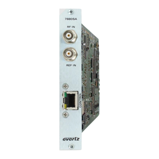
Page 12: Figure 2.1-2 : 7880Sa Rear Panel
7880SA User Manual Figure 2.1-1 Figure 2.1-2 : 7880SA Rear Panel Page 2... -
Page 13: Specifications
7880SA User Manual SPECIFICATIONS 2.1. RF INPUT Number Connector 50Ω BNC Input Frequency 5 to 3000 MHz Input Power -110 to +5 dBm (aggregate) Maximum Safe Input +15 dBm Noise Floor -160 dBm/Hz typical at min atten, -160 dBm/Hz typical at max... -
Page 14: Measurement Speed
7880SA User Manual 2.6. MEASUREMENT SPEED • 500 MHz span 1 MHz RBW, 200 ms • 200 MHz span 30 kHz RBW, 630 ms • 80 MHz span 100 kHz RBW, 170 ms 3.5 MHz span • 8kHz RBW, 90 ms 2.7. -
Page 15: Operation Guide
• A web browser such as Internet Explorer, Safari or Firefox • Java JVM 1.4.2 or newer for 7880SA software versions up to 1.5.13 and Java JDK 1.6, release 10 or newer for 7880SA software versions 2.0.0 and up •... - Page 16 7880SA User Manual This page left intentionally blank Page 6...
-
Page 17: 80Sa Installation And Configuration
7880SA. With shared access, an Ethernet cable is connected between the 7880SA and a hub or switch. In this configuration any computer on the network can access the 7880SA. Any hub or switch is compatible with the 7880SA but 10BaseT products will slow down the measurement speed. -
Page 18: Accessing The Wcm
• Gateway = 192.168.10.1 To access the WCM, enter <7880SA IP address>/cgi-bin/wmc.cgi into a web browser’s address bar. For example, to access the 7880SA on the default IP address, use the following: http://192.168.10.1/cgi-bin/wcm.cgi This will display the following web page (Figure 4-1). To log in, select an access level and enter the password. -
Page 19: Modifying The Network Configuration
User Manual 4.3.2.2. Modifying the Network Configuration To change the 7880SA’s network configuration, log in to the Web Configuration Manager and navigate to the Network tab as is shown in Figure 4-2. Figure 4.3-2 : Changing the 7880SA’s network configuration Enter the network information and click Save Changes. -
Page 20: Restoring The Factory Defaults
Click “Reboot Now” to reboot the card and begin using the new settings. 4.3.2.3. Restoring the Factory Defaults The reset switch on the rear of the 7880SA can be used to restore the 7880SA’s network configuration to the defaults. Any calibration or license files installed will remain unchanged. The procedure to restore the factory default settings is as follows: 1. -
Page 21: Java Applet Software
Internet Explorer, Safari or Firefox. Note that the new versions of Google Chrome (Version 45 and up) has blocked the use of Java applets and will not run the 7880SA Applet. The GUI is quite intuitive to use and allows interactive use of the 7880SA for any general purpose investigation that a traditional digital or analog spectrum analyzer can be used for. -
Page 22: Control Buttons And Menu
The following tables describe in detail each button and data field of the 7880SA’s GUI. Use of the GUI is described further in the Help file under the system button. -
Page 23: Figure 4.4-3 : 7880Sa Gui Control Buttons
7880SA User Manual Figure 4.4-3 : 7880SA GUI Control Buttons Page 13... -
Page 24: Table 1: 7880Sa Gui Button And Menu Descriptions (Continue)
7880SA User Manual Button Menu Item Description Sets the 7880SA back to its default settings and clears Preset any stored traces, states and markets. 7880SA Logo This is the application logo only. The Center Frequency displays the desired and actual center frequency values. -
Page 25: Table 2: 7880Sa Gui Button And Menu Descriptions (Continue)
The number of averages. Displays the desired and actual number of Average averages. Clicking on the menu item displays the Number of Averages Edit dialog. Lower limit is 1. The video bandwidth used when capturing a trace. Table 2: 7880SA GUI Button and Menu Descriptions (Continue) Page 15... -
Page 26: Table 3: 7880Sa Gui Button And Menu Descriptions (Continue)
Hold Normal (None), Max Hold, Min Hold and Min Max Active. Store to restore the state of 7880SA from storage of one of 10 states. When the state is captured, a gear marker icon is shown on the menu item. Hovering over the menu item when a state is captured, displays the state in an HTML tool tip. -
Page 27: Table 4: 7880Sa Gui Button And Menu Descriptions (Continue)
Color Scheme Normal (Black and Green) Print (White and Black) The number of seconds to wait for a response from the 7880SA in addition to a minimum of a second. Default is 30 seconds. Connection Minimum is 1 second. -
Page 28: Table 5: 7880Sa Gui Button And Menu Descriptions (Continue)
Export to CSV: Export the Trace points to a CSV file. Displays a File Save as Dialog. Details: This field displays the setting at the time the frame was captured. Back: This field navigate back to the Trace menu list. Table 5: 7880SA GUI Button and Menu Descriptions (Continue) Page 18... - Page 29 7880SA User Manual Button Menu Item Description Markers that can be applied to traces. The markers are added to the active trace and then can be moved to memory-based traces. The trace color is shown in the menu item. Note that markers can only be dragged using the mouse on memory-based traces that have the Freq.
- Page 30 This field exports the screen, traces, markers and states to an HTML file report. It displays a File Save as Dialog to specify a target Export to directory. The 7880SA UI optionally displays the report HTML file in HTML the default browser when done.
-
Page 31: Table 6: 7880Sa Gui Button And Menu Descriptions (Continue)
Tolerance Power: Edit the default Tolerance Power in dBm. Displays sub menu for the default presence of a carrier analysis. Presence of a Carrier Delta Power: Edit the default Delta power in dB. Table 6: 7880SA GUI Button and Menu Descriptions (Continue) Page 21... -
Page 32: Advanced Measurement Settings
Save/Open xml file. Opens a saved project from file and loads the data into the 7880SA UI. The current settings, memory based traces, markers attached Open Project to memory based traces, and states are loaded from the project xml file. -
Page 33: Overview Bar
4.4.3. Overview Bar The Overview Bar is a navigational assistance feature recently added in the 7880SA to help the user to set center frequency and span more efficiently. It is a full span bar that provides an overview of the entire spectrum. -
Page 34: Carrier Monitor (Optional With License)
User Manual 4.4.4. Carrier Monitor (Optional with License) The 7880SA can be configured to monitor up to 100 carriers, validating the captured trace for limits within acceptable Band Power and Presence of a Carrier thresholds. The measurement is defaulted to use the entire span of the view port. -
Page 35: Carrier Monitor Toolbar
7880SA User Manual A unique name must be giving to each new measurement. Use the drop down box to configure the options for Analyses, Notifications, and State. Note that the state options are not configurable through this menu. These values are determined from the current Java Applet configuration. -
Page 36: Play
Delete Delete the selected measurement Edit Edit the selected measurement Recall State Recall the 7880SA state from the selected measurement Capture the state of the 7880SA to the selected Capture State measurement Move measurement Move the selected measurement down one... -
Page 37: Edit A Measurement
The individual SNMP notification is on within the measurement 4.4.5. SNMP Interface The 7880SA supports monitoring of the operational status through the SNMP interface. MIB definitions are available to provide translations of the OIDs to readable labels. The SNMP interface provides read- only data concerning the device operations. -
Page 38: Input Signal Consideration
Input Signal consideration The input to the 7880SA must be in the range listed in specifications section. Note that the input can be limited by an external filter to the band of interest within this range in order to avoid reducing the signal to noise ratio of the instrument. -
Page 39: Figure 4.4-7: Firmware Upgrade Tab
User Manual Figure 4.4-7: Firmware Upgrade Tab The firmware update file, supplied by Evertz, can be transferred to the 7880SA using a local host computer. After specifying the server information and clicking Upload, the file will be obtained and then the following screen will be displayed: Figure 4.4-8: Flash Firmware Window... - Page 40 SAFETY CONSIDERATIONS The 7880SA User’s Manual must be reviewed before installation and operation of the unit. Failure to do so can result in damage to the unit or injury to the user. If the equipment is used in a manner not specified by the manufacturer, the protection provided by the equipment may be impaired.
- Page 41 7880SA User Manual WARRANTY/REPAIR CONTACT INFORMATION If your 7880SA is not operating correctly, contact the Service Department for support and a Return Material Authorization (RMA) number if applicable. There are no serviceable parts inside the unit. EVERTZ MICROSYSTEMS LTD. 5288 John Lucas Drive...
- Page 42 7880SA User Manual End of Document Page 32...
Need help?
Do you have a question about the 7880SA and is the answer not in the manual?
Questions and answers