
Related Manuals for Grundfos LSV Series


Summary of Contents for Grundfos LSV Series
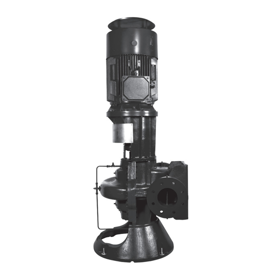
- Page 1 GRUNDFOS INSTRUCTIONS Single-stage vertical split case pump and double-stage vertical split case pump Installation and operating instructions...
- Page 3 English (GB) Installation and operating instructions ........4...
-
Page 4: Table Of Contents
English (GB) Installation and operating instructions Original installation and operating instructions Technical data ....33 Operating conditions ... . . 33 Table of contents Flange forces and torques . -
Page 5: General Information
If these instructions are not observed, it Grundfos LSV vertical split-case pumps are supplied may result in malfunction or damage to the either as a complete pump with motor, base frame equipment. -
Page 6: Temporary Storage
2.2 Temporary storage 3.2.1 Lifting the product If you do not store or operate the pump soon after WARNING arrival, store it in a clean, dry place with slow, Crushing of hands moderate changes in ambient temperature. Protect Death or serious personal injury the pump from moisture, dust, dirt and foreign bodies. - Page 7 How to lift and handle the LSV bare-shaft pumps by means of the pump flange and hanging ear How to lift and handle the LSV bare-shaft pumps by means of a U-type unbuckle How to lift and handle the LSV bare-shaft pumps by means of the pump flange...
- Page 8 3.2.2 Foundation We recommend that you install the pump on a concrete foundation, which is heavy enough to provide permanent and rigid support for the entire pump. The foundation must be capable of absorbing any vibration, normal strain or shock. We recommend that the weight of the concrete foundation is 3 times the weight of the complete pump unit.
- Page 9 3.2.5 Building up the foundation The foundation procedure has three steps: 1. pouring of foundation 2. shimming of base frame 3. grouting. Pouring of foundation We recommend the following procedure to ensure a LSV anchor bolt installation good foundation: 1. Pour the foundation without interruptions to within Pos.
-
Page 10: Electrical Connection
3.3 Electrical connection Grouting Grouting compensates for uneven foundation, The electrical connections must be carried out by an distributes the weight of the unit, dampens vibrations authorised electrician in accordance with local and prevents shifting. Use an approved, non- regulations. shrinking grout. -
Page 11: Pipes
3.4 Pipes 3.3.1 Frequency converter operation You can connect all three-phase motors to a Protective covers are fitted to the inlet and frequency converter. outlet ports to prevent foreign bodies from However, frequency converter operation often entering the pump during transportation exposes the motor insulation system to a heavier load and installation. - Page 12 3.4.2 Inlet pipes 3.4.5 Auxiliary pipes Place the pump below system liquid level whenever Drains possible. This will facilitate priming, assure a steady Install the drain pipes from the pump casing and liquid flow and provide a positive suction head. stuffing boxes to a convenient disposal point.
-
Page 13: Inlet Pipe Guidelines
3.5 Inlet pipe guidelines 3.5.1 Common guidelines Avoid air pockets or turbulence in the inlet pipe Never use reducers in a horizontal inlet pipe as shown in figure below. Instead, use an eccentric reducer as illustrated in figure below. Correct Wrong Reducers resulting in air pockets and turbulence Correctly mounted reducer... - Page 14 3.5.3 Suction lift systems Closed systems and open systems where the liquid level is below the pump inlet. Install the inlet pipe sloping upwards towards the inlet port. Any high point in the pipe will be filled with air and thus prevent proper operation of the pump.
- Page 15 3.5.5 Inlet pipe with a horizontal elbow in the feed line Make sure that the liquid flow is evenly distributed to both sides of the double-suction impeller. There is always an uneven, turbulent flow through an elbow. See below. If you install an elbow in the inlet pipe near the pump in a position other than vertical, more liquid will enter one side of the impeller than the other.
-
Page 16: Starting Up The Product
3.5.6 Installations with vertical inlet pipe in 4.1.2 Flushing the pipe system confined space The pump is not designed to pump liquids containing solid particles such as pipe debris and welding slag. Before starting up the pump, the pipe system must be thor- oughly cleaned, flushed and filled with clean water. -
Page 17: Priming
4.4 Startup 4.2.4 Direction of rotation Check the direction of rotation in the following way: Make sure that the pump is filled with liq- 1. Disconnect the two coupling halves between uid. The pump must not run dry. Dry-run- pump and motor. ning will cause serious damage to the stuffing boxes, shaft seals, wear rings and 2. -
Page 18: Alignment
4.5 Alignment Check shaft alignment after the pump installation is completed. The following anchoring and alignment procedures are typical and, if performed with care, should result in a smooth-running, trouble-free installation. If the pump and motor were shipped mounted on the pump base as an assembly, remove the coupling guard. -
Page 19: Product Introduction
5. Product introduction 5.1 Applications Grundfos LSV vertical split-case pumps are typically used in these applications: • circulation in heating- and air-conditioning systems, water condensing and boiler feed systems • liquid transfer and pressure boosting in various industrial systems •... -
Page 20: Identification
5.3 Identification The type designation and rating information of Grundfos vertical split-case pumps are stated on the nameplate. See figure below. The type designation includes model number, size and type. Permanent records for this pump are kept under its serial number and production date (see figure below, pos. - Page 21 5.3.2 Type key Example: LSV125-100-305X ,(W) 1F1DS BBQE 1 Pos. Example -100 -305x ,(W) BBQE Pos. Code Explanation Type range LSV: Vertical version Nominal diameter of inlet port (DN) -100 Nominal diameter of outlet port (DN) Maximum impeller diameter [mm] -305x If suffix "x"...
- Page 22 Pos. Code Explanation Pump variant 1: Grease-lubrication For LS, pump with motor, common base frame and non-spacer coupling For LSV, pump with motor, base frame, motor stool and non-spacer coupling 2: Grease-lubrication For LS, bare shaft pump with common base frame, non-spacer coupling For LSV, pump with base frame, motor stool and non-spacer coupling 3: Grease-lubrication For LS, bare shaft pump...
- Page 23 Pos. Code Explanation B: SS420 and bronze Code for shaft and sleeve materials A: SS420 and SS304 D: SS420 and no sleeve C: SS420 and SS316 E: SS304 and no sleeve K: Duplex stainless steel and duplex stain- less steel J: SS316 and no sleeve Q: Alloy steel and no sleeve L: Duplex stainless steel and no sleeve...
- Page 24 Pos. Code Explanation Direction of rotation (Pump direction of rotation as seen from motor end) 1 Clockwise 2 Counterclockwise Antimony, not approved for potable water. The example shown is an LS 125-100-305F/273.1, standard type with standard coupling, DIN PN 16 flange, cast iron pump casing with SS304 impeller, BBQE mechanical shaft seal and clockwise direction of rotation.
-
Page 25: Servicing The Product
Electric shock toxic. Death or serious personal injury If you request Grundfos to service the product, ‐ Before starting work on the pump, contact Grundfos with details about the liquid before make sure that the power supply has returning the product for service. - Page 26 6.3.2 Frequency of inspections 6.3.3 Lubrication Carry out inspections in accordance with the Pump bearings maintenance table below. Pump bearings are lubricated before delivery. Depending on operating and environmental We recommend relubricating at intervals of 2000 conditions together with a comparison of previous operating hours.
-
Page 27: Taking The Product Out Of Operation
In cold-liquid installations, pay special attention to the risk of injury caused by cold liquids and cold surfaces. Grundfos recommends KYODO YUSHI MULTEMP SRL grease for relubrication. 1. After draining the pump during long shutdown periods under freezing conditions, blow out all... -
Page 28: Fault Finding The Product
8. Fault finding the product DANGER Electric shock Death or serious personal injury ‐ Before you remove the terminal box cover and before you remove or dismantle the pump, make sure that the power supply has been switched off and that it cannot be accidentally switched on. 8.1 The pump delivers no liquid Cause Remedy... -
Page 29: The Pump Does Not Create Enough Pressure
Replace the packing rings. The impeller diameter is too small. • Check with Grundfos if you can use a larger impeller. If not, reduce the outlet pipe friction losses. But be careful not to overload the motor. Obstruction in pump housing. -
Page 30: The Pump Loses Liquid After Running For A Short Time
The viscosity or specific gravity of the pumped liquid • Use a larger motor. Consult Grundfos for is higher than that of water. recommended size. •... -
Page 31: The Motor Is Overloaded
8.6 The motor is overloaded Cause Remedy The viscosity or specific gravity of the pumped liquid • Use a larger motor. Consult Grundfos for is higher than that of water. recommended size. • Test the liquid for viscosity and specific gravity. -
Page 32: Cavitation Noise
Cause Remedy • Retighten the anchor bolt nuts. Make sure that the foundation is made according to the installation and operating instructions. 8.8 Cavitation noise Cause Remedy Air leak in the inlet pipe or flange. • Replace or repair the defective pipe section or flange. -
Page 33: Original Installation And Operating Instructions 9. Technical Data
NPSH curve for the pump + a safety margin of output. minimum 0.5 metres head. In cases where both the maximum temperature and NPSH appears from the data booklet and Grundfos the maximum altitude are exceeded, the derating Product Centre. factors must be multiplied (0.88 x 0.78 = 0.69). - Page 34 This will result in overheating of the motor. In such situations, throttle the valve on the outlet side instead. If an automatic throttle valve is installed, this can be done automatically. 9.1.5 Frequency of starts and stops The recommended maximum number of starts is 3 per hour for complete pumps with a motor supplied by Grundfos.
-
Page 35: Flange Forces And Torques
9.2 Flange forces and torques Vertical pump, side branch, y-axis If not all loads reach the maximum permissible value, one of the values may exceed the normal limit. Contact Grundfos for further information. Flange forces and torques Force [N] Torque [Nm]... -
Page 36: Disposing Of The Product
1. Use the public or private waste collection service. 2. If this is not possible, contact the nearest Grundfos company or service workshop. The crossed-out wheelie bin symbol on a product means that it must be disposed of separately from household waste. - Page 37 Argentina China Greece Bombas GRUNDFOS de Argentina S.A. GRUNDFOS Pumps (Shanghai) Co. Ltd. GRUNDFOS Hellas A.E.B.E. Ruta Panamericana km. 37.500industin 10F The Hub, No. 33 Suhong Road 20th km. Athinon-Markopoulou Av. 1619 - Garín Pcia. de B.A. Minhang District P.O. Box 71 Tel.: +54-3327 414 444...
- Page 38 Fax: +66-2-725 8998 Fax: + 370 52 395 431 Москва, RU-109544, Russia Turkey Тел. (+7) 495 564-88-00 (495) 737-30-00 Malaysia GRUNDFOS POMPA San. ve Tic. Ltd. Факс (+7) 495 564 8811 GRUNDFOS Pumps Sdn. Bhd. Sti. E-mail grundfos.moscow@grundfos.com 7 Jalan Peguam U1/25 Gebze Organize Sanayi Bölgesi...
- Page 39 99572451 06.2022 ECM: 1341641 www.grundfos.com...
Need help?
Do you have a question about the LSV Series and is the answer not in the manual?
Questions and answers