Table of Contents
Advertisement
Quick Links
Advertisement
Table of Contents

Subscribe to Our Youtube Channel
Related Manuals for Freedom Enterprise MisMatcher01


Summary of Contents for Freedom Enterprise MisMatcher01
- Page 2 By reading this manual you’ll become familiar with the MisMatcher01, how to use it and how to make the most of it. Good luck, have...
-
Page 3: Table Of Contents
CONTENTS II. BASIC MISMATCHER 01 REV.B FEATURES III. ASSEMBLY A. BUILD OF MATERIALS B. USER INTERFACE C. MAIN PCB IV. BOOTING UP V. PASSIVE MIXERS / ATTENUATORS VI. SYNC SEPARATOR AND SYNC MIXER VII. ENHANCER VIII. TROUBLESHOOTING IX. USER INTERFACE X. -
Page 4: Basic Mismatcher 01 Rev.b Features
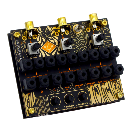
Video inputs, such as cameras or VCRs, and outputs, such as monitor or ADCs, can be connected to the MisMatcher01 trough three RCA jacks. The user interface provides users with various patch point, enabling them to interconnect different parts of the circuit together for a vast array of effects. -
Page 5: Assembly
III. ASSEMBLY A. BUILD OF MATERIALS Value Description Designator Quantity 1 nF Ceramic Capacitor C1, C5, C22 0.1 μF Ceramic Capacitor C2, C6, C7, C10, C11, C12, C14, C16 220 μF Electrolytic Capacitor C3, C4, C8, C9, C13, C15 10 nF Ceramic Capacitor Header 1X8 M Micro USB Board... -
Page 6: User Interface
B. USER INTERFACE Start by placing the PJ-341 jacks and solder them. Snap the gold RCA jacks and potentiometers in place. Place the LED in the right orientation as well as the 270 current limiting resistor. Solder these remaining components. The male header will be soldered later on. To passively mix two video signals with one potentiometer, solder a 500 resistor from one fixed end of potentiometer A to the wiper, and... - Page 7 Snap the three potentiometers in place along with the DIP switch and jumpers. Solder them. Place the LM1881’s socket in place. When soldering, jump pin 2 and 3 together with solder. Trim pin 3 off the LM1881. Install the LM1881 only after soldering the socket.
-
Page 8: Booting Up
IV. BOOTING UP With the 2 PCBs mounted together, connect a Micro USB charger to the Micro USB port and turn the switch on. The LED should light up. Connect a video source to jack A and a monitor do jack C. Patch these 2 points together and you should see the source on the monitor. -
Page 9: Sync Separator And Sync Mixer
VI. SYNC SEPARATOR AND SYNC MIXER The key to a stable picture is a good sync signal. The mixing, attenuation and distortion of video signals can deteriorate sync, leading to horizontal or vertical scrolling of video on screen. When the lost of sync is undesired by the user, the sync separator and sync mixer can come into play. -
Page 10: Enhancer
VIDEO BURST Composite Video Composite Sync VII. ENHANCER This video enhancer can be used to either boost saturation and sharpness of the video or, using the provided Gain and Feedback 1 and 2 controls, to distort the video and create interesting effects. The gain controls how much the signal is amplified. -
Page 11: Troubleshooting
VIII. TROUBLESHOOTING The LED doesn’t turn on. Test condition: power on, all DIP switch positions off, gain at full 1. Using a multi-meter, check CCW position, all 75 jumpers on, for 5V on the oscilloscope probing no inputs connected. points. If 5V are present, confirm All measures in V the LED is in the correct orientation. -
Page 12: User Interface
IX. USER INTERFACE... - Page 13 1 RCA Connector A 7.3 Potentiometer B Fixed Access Point 1.1 RCA Access Point A 8 Power LED 2 Micro USB 9 Potentiometer C 3 RCA Connector B 9.1 Potentiometer C Fixed 3.1 RCA Access Point B Access Point 4 On/Off Switch 9.2 Potentiometer C Wiper 5 RCA Connector C Access Point...
-
Page 14: Patching Examples
X. PATCHING EXAMPLES Dirty Mixer with Sync Fade between two different video signals but preserve the sync of one of them. VIDEO SYNC SEPARATOR MONITOR SYNC MIXER VIDEO... - Page 15 Edge Detection Use the Gain and Feedback controls of the Enhancer to achieve the desired result. Use a potentiometer to attenuate the signal coming into the Enhancer and use another one to fade between the clean and glitched signal. SYNC SEPARATOR SYNC MIXER VIDEO MONITOR...
- Page 16 Total Signal Annihilation Completely destroy your video signal with the Enhancer and then restore some of it’s former glory with the Sync Mixer. Attenuate the signal coming into the Sync Separator and use the Low Pass Filters for an extra layer of effects.
-
Page 17: Specifications
The PCBs layout, artwork and names are the property of Freedom Enterprise and may not be cloned or replicated for commercial purposes. Read the full license at creativecommons.org/... -
Page 18: Warranty
XIII. WARRANTY Fully assembled versions of this product are covered by warranty for one year following the date of purchase. This warranty covers any defect in the manufacturing of this product, such as assembly errors or faulty components. This warranty does not cover any damage or malfunction caused by incorrect use, such as, but not limited to, power cables connected backwards, excessive voltage levels, or exposure to extreme temperature or moisture levels. - Page 19 MISMATCHER01 REV.B OWNER’S MANUAL Revision A August 2020 Written by Pedro Silva Art by Seni...
Need help?
Do you have a question about the MisMatcher01 and is the answer not in the manual?
Questions and answers