Table of Contents
Advertisement
Quick Links
Advertisement
Table of Contents

Subscribe to Our Youtube Channel
Related Manuals for Freedom Enterprise MisMatcher01 Rev.D


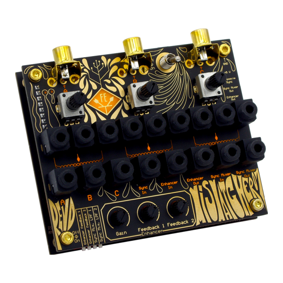
Summary of Contents for Freedom Enterprise MisMatcher01 Rev.D
- Page 2 WARNING - WHEN USING ELECTRIC PRODUCTS, THESE BASIC PRECAUTIONS SHOULD ALWAYS BE FOLLOWED. 1. Read these instructions. 2. Keep these instructions. 3. Heed all warnings. 4. Follow all instructions. 5. Do not use apparatus near water - for example, but not limited to: near a bathtub, washbowl, kitchen sink, in a wet basement, or near a swimming pool or the like.
- Page 3 By reading this manual you’ll become familiar with the MisMatcher01, how to use it and how to make the most of it. Good luck, and have a great experience with your brand-new video glitcher from Freedom Enterprise.
-
Page 4: Table Of Contents
CONTENTS ASSEMBLY User Interface Main PCB CONTROLS Misc Mixer/Attenuators Enhancer Sync Mixer PRINCIPLE OF OPERATION BASICS OF ANALOG VIDEO SIGNALS FEATURES Passive Mixers / Attenuators Sync Separator And Sync Mixer Enhancer PATCHING EXAMPLES SPECIFICATIONS WARRANTY... -
Page 5: Assembly
ASSEMBLY Assembly of the new MisMatcher01 REV.D has been greatly simplified compared to previous versions. With most of its critical components already soldered in place, users only have to solder a handful of jacks and potentiometers, reducing human error during assembly. - Page 6 Start by snapping the three potentiometers in place, followed by the three gold RCA jacks and lastly the seventeen PJ-341 jacks. Secure the PCB and solder these components. Keep in mind that some components might move when you flip the PCB upside down or while soldering. To avoid this, press the components against the PCB as the solder flows to ensure their most upright position.
-
Page 7: Main Pcb
Main PCB Start by snapping the three potentiometers in place as well as the piano DIP switch. To ensure the correct placement of the power switch and the male and female header, place these components and then secure the two PCBs with the 8 screws and four standoffs provided. -
Page 8: Controls
CONTROLS Misc Oscilloscope Micro USB Power On/Off Switch probing points... - Page 9 RCA A RCA B RCA C RCA A RCA B RCA C access point access point access point...
-
Page 10: Mixer/Attenuators
Mixer/Attenuators Potentiometer Potentiometer’s wiper Potentiometer’s fixed end... -
Page 11: Enhancer
Enhancer Enhancer Output Enhancer Input Feedback 1 amount Feedback 2 enable Gain amount Feedback 1 enable Feedback 2 amount... -
Page 12: Sync Mixer
Sync Mixer Sync Mixer Output Sync Mixer Input Low pass filter 2 Sync Separator Input Low pass filter 1... -
Page 13: Principle Of Operation
PRINCIPLE OF OPERATION An electronic analog video glitcher is a device designed to distort analog Sync In Sync Separator video signals using analog circuitry. The MisMatcher 01 works with composite video, the yellow RCA jack from cameras and monitors, and contains three different analog circuits, Sync Sync Mixer Input Sync Mixer... -
Page 14: Basics Of Analog Video Signals
BASICS OF ANALOG VIDEO SIGNALS Colour Burst H SYNC Video One Raster Line An electronic analog video glitcher is a A composite video signal, or CVBS, is comprised of colour or chroma, video or luma, blanking and sync information in only one channel. -
Page 15: Features
FEATURES Passive Mixers / Attenuators The three potentiometers in the user interface can be used to either attenuate the intensity of a video signal, or to fade between two different video signals. The potentiometer’s jacks are automatically connected to ground if no patch cable is inserted. -
Page 16: Enhancer
Enhancer This enhancer can be used to either boost saturation and sharpness of the video or, using the provided Gain and Feedback 1 and 2 controls, to distort the video and create interesting effects. The gain controls how much the signal is amplified. Feedback 1 and 2 takes video from different stages of the circuit and feeds it back into the Enhancer’s input. -
Page 17: Patching Examples
PATCHING EXAMPLES CAMERA MONITOR In this first example connect camera A to RCA A and monitor A to RCA C. Then patch camera A to Enhancer In and monitor A to Enhancer Out. Control the enhancer trough its gain, feedback 1 and 2 knobs, as well as the DIP switch. - Page 18 MONITOR CAMERA You may find that, if you push the Enhancer too hard, you may lose sync on your monitor. To solve this, first split camera A into Sync In and Enhancer In. Then patch the Enhancer Out into the Sync Mixer In and finally Sync Mixer Out to monitor A. This way you restore your video’s sync after the Enhancer, with the help of the Sync Mixer, using the video signal provided on the Sync In as reference.
- Page 19 MONITOR CAMERA You can take it one step further and use the Sync Mixer as a glitcher. Split camera A into one of the pot’s fixed end and into another pot’s fixed end. Patch the first pot’s wiper to the Sync In. Patch the second pot’s wiper to the Enhancer In.
- Page 20 MONITOR CAMERA CAMERA You don’t have to limit your workflow to only one camera. In this example we’ll create a more advanced Karl Klomp style video mixer. Connect camera A to RCA A, camera B to RCA B and monitor A to RCA C. Split camera A onto the first pot’s fixed end and the third pot’s fixed end.
- Page 21 MONITOR MONITOR CAMERA If you are more interested in the duality of two monitors you can glitch one camera with the Sync Mixer and Enhancer, separately, and send each one to its respective monitor. Connect camera A to RCA A, monitor A to RCA B and monitor B to RCA C.
-
Page 22: Specifications
SPECIFICATIONS Size 100x83 mm DC Input Power Consumption 170 mA @ 5 V Video Format NTSC/480i & PAL/576i Voltage Level pk=pk WARRANTY Fully assembled versions of this product are covered by warranty for one year following the date of purchase. This warranty covers any defect in the manufacturing of this product, such as assembly errors or faulty components. - Page 23 Mismatcher 01 REV. D | Owner’s Manual Revision A April 2021 Written by Pedro Silva | Art by Seni freedomenterprise.pt help@freedomenterprise.pt © 2021 Freedom Enterprise Note: Specifications subject to change without notice...
Need help?
Do you have a question about the MisMatcher01 Rev.D and is the answer not in the manual?
Questions and answers