
Related Manuals for SELT SB500


Summary of Contents for SELT SB500
- Page 1 DT-E OPERATION AND MAINTENANCE MANUAL ASSEMBLY AND SAFE OPERATION MANUAL Steel and aluminium components and structural sets Pergola SB500...
- Page 2 THIS OPERATION AND MAINTENANCE MANUAL: is valid from 1 May 2019 and is applicable to the above listed product versions. DT-E 5.4: ALUMINUM STRUCTURE - PERGOLA SB500 SYSTEM Version 3 / May 2019 / PL page 2 / 48...
-
Page 3: Table Of Contents
Marking and labelling of the product with CE mark ....................48 10.1 Conformity of product with the CE standard ......................48 10.2 Information accompanying the CE marking ......................48 DT-E 5.4: ALUMINUM STRUCTURE - PERGOLA SB500 SYSTEM Version 3 / May 2019 / PL page 3 / 48... -
Page 4: Introduction
HAZARD! hazard. Risk: hazard of serious personal injury or death. Hazardous operation which could cause injuries or damages of the product. DT-E 5.4: ALUMINUM STRUCTURE - PERGOLA SB500 SYSTEM Version 3 / May 2019 / PL page 4 / 48... -
Page 5: Terms And Definitions
For the purposes of this documentation the following terms definitions shall apply: Product: PERGOLA SB500 The Pergola SB500 system is made of powder-coated aluminum profiles and components made of stainless and galvanised steel. Roof framework made of movable aluminium blades. Angle of inclination of the blades can be changed. Product design is offered in colour from RAL colour chart after confirmation of their availability by the manufacturer. - Page 6 SELT Sp. z o.o. shall not be responsible for damages resulting from non-observance of the recommendations included in this documentation. For further improvement of the product, SELT Sp. z o.o. reserves the right to introduce changes, which, while maintaining significant technical parameters, will be considered appropriate for increasing the quality of product operation and safety of use.
-
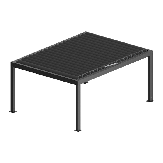
Page 7: Product Technical Information
Pergola SB500 - standalone Fig. 1. Standalone Pergola SB500 - Dimensions: B max – maximum width, L max – maximum length, H max – frame maximum height, H1 max – free clearance of the frame, H2 max – maximum height of position of the mechanism intended to change angle of the blades. - Page 8 Detailed data for parameters of the individual motors are available on the websites of motor manufacturers and on the website: www.selt.com→ OUR OFFER → AUTOMATION DT-E 5.4: ALUMINUM STRUCTURE - PERGOLA SB500 SYSTEM Version 3 / May 2019 / PL page 8 / 48...
-
Page 9: Product Specification
They have the following features: Mobile roof opens electrically; it is possible to install systems by Selt Sp. z o.o. on walls Protects against sun and rain. -
Page 10: Transport And Storage Of The Products
COMPLETENESS AND QUALITY CONDITION OF TH E DELIVERY SELT Sp. z o.o. makes every effort to ensure that the product matches your order. However, checking of product completeness should be done by the Purchaser and take place when it is received. -
Page 11: Product Assembly
This chapter contains general requirements concerning the product assembly. Correct assembly is a necessary condition for smooth operation of the product. SELT Sp. z o.o. recommends using only professional assembly crews, which guarantee the Purchaser that the conducted installation will be correct. -
Page 12: Preparation For Assembly
SELT shall not be responsible for damages caused by use of too weak anchoring components or fixing in the floor with too small load bearing capacity (the purchaser is responsible for the proper installation or fixing of the system), ... -
Page 13: Assembly Tools
Blade opening direction Pergola front Open blades Blade opening direction Pergola front Fig. 2. Standard blade opening direction setting for Pergola SB500. ASSEMBLY TOOLS Assembly instructions, operation and maintenance manual and instructions for safe use are available at www.selt.com after... - Page 14 Fig. 3. Marking of components of support structure for Pergola SB500. In case of Pergola SB500, various types of footings may be installed inside columns. As a result, it is possible to set and anchor the structure in various ways according to the customer's needs, including installation in a corner.
-
Page 15: Guidelines For Setting And Anchoring The Pergola Support Structure
4.6.1.1 GUIDELINES FOR SETTING AND ANCHORING THE PERGOLA SUPPORT STRUCTURE Before the support structure is set, places in which the Pergola SB500 columns have to be determined. To perform the above-mentioned task properly, follow these guidelines and good building practices. - Page 16 There should be places for anchors where the Pergola SB500 support structure is installed. Hole spacings and locations for the structure to be anchored are shown in Figure 4. The support structure should be installed only in a level and load-bearing substrate with permanent ground coordinates over the entire installation surface or variable ground coordinates over the installation surface under selected column footings if the support structure design has provided for it.
-
Page 17: Pergola Support Structure Installation
Incorrect anchoring methods CONCRETE/FOUNDATION RIGID INCOMPRESSIBLE SURFACE GROUND Fig. 6. Guidelines for anchoring the Pergola SB500 support structure. Foundation 4.6.1.2 PERGOLA SUPPORT STRUCTURE INSTALLATION 1. Install the front footing to the front column in accordance with Figure 1 and 2. Repeat for the other front column. - Page 18 Figure 4 Figure 5 NOTE: The rear footing may be of type A, B, C, D, E, or F. Figure 6 DT-E 5.4: ALUMINUM STRUCTURE - PERGOLA SB500 SYSTEM Version 3 / May 2019 / PL page 18 / 48...
- Page 19 6. Screw the rear beam plugs to the sockets in the rear columns. According to Figures 10, 11, and 12. Figure 10 DT-E 5.4: ALUMINUM STRUCTURE - PERGOLA SB500 SYSTEM Version 3 / May 2019 / PL page 19 / 48...
- Page 20 According to Figures 13 and 14. NOTE: Remember to support the side beam in order to prevent the structure from falling down. Figure 13 Figure 14 DT-E 5.4: ALUMINUM STRUCTURE - PERGOLA SB500 SYSTEM Version 3 / May 2019 / PL page 20 / 48...
- Page 21 According to Figures 17 and 18. NOTE: Remember to support the side beam in order to prevent the structure from falling down. Figure 17 Figure 18 DT-E 5.4: ALUMINUM STRUCTURE - PERGOLA SB500 SYSTEM Version 3 / May 2019 / PL page 21 / 48...
- Page 22 15. Put the front beam into the sockets in the front columns. According to Figures 21, 22, and 23. Figure 21 Figure 22 DT-E 5.4: ALUMINUM STRUCTURE - PERGOLA SB500 SYSTEM Version 3 / May 2019 / PL page 22 / 48...
- Page 23 17. Screw the front beam plugs to the sockets in the front columns. According to Figures 24, 25, and 26. Figure 24 Figure 25 Figure 26 DT-E 5.4: ALUMINUM STRUCTURE - PERGOLA SB500 SYSTEM Version 3 / May 2019 / PL page 23 / 48...
- Page 24 According to Figures 28-31. NOTE: Remember to install the seal between the gutter and beam. Figure 28 Figure 29 DT-E 5.4: ALUMINUM STRUCTURE - PERGOLA SB500 SYSTEM Version 3 / May 2019 / PL page 24 / 48...
- Page 25 21. Place left gutter with respect to openings in the side beam. According to Figures 32-35. NOTE: Remember to install the seal between the gutter and beam. Figure 32 Figure 33 DT-E 5.4: ALUMINUM STRUCTURE - PERGOLA SB500 SYSTEM Version 3 / May 2019 / PL page 25 / 48...
- Page 26 37. NOTE: The extra rear blade consists of two identical components installed next to each other. Figure 36 Figure 37 DT-E 5.4: ALUMINUM STRUCTURE - PERGOLA SB500 SYSTEM Version 3 / May 2019 / PL page 26 / 48...
- Page 27 Figure 38 Figure 39 Blade view, drive side. Figure 40 Blade view, bearing side. Figure 41 DT-E 5.4: ALUMINUM STRUCTURE - PERGOLA SB500 SYSTEM Version 3 / May 2019 / PL page 27 / 48...
- Page 28 Figure 44 NOTE: Insert the pin into the bearing in the left beam from the drive side of the blade. Figure 33 DT-E 5.4: ALUMINUM STRUCTURE - PERGOLA SB500 SYSTEM Version 3 / May 2019 / PL page 28 / 48...
- Page 29 NOTE: Install retaining rings for the pins on the drive and bearing sides of the blade. Make sure the pin does not damage the coat of paint. Figure 47 DT-E 5.4: ALUMINUM STRUCTURE - PERGOLA SB500 SYSTEM Version 3 / May 2019 / PL page 29 / 48...
-
Page 30: Drive Assembly
4. Screw disassembled from handle of wrapping connector should be installed to drive plug of the blade with NORD-LOCK washers, as on the picture 12. Picture 2 DT-E 5.4: ALUMINUM STRUCTURE - PERGOLA SB500 SYSTEM Version 3 / May 2019 / PL page 30 / 48... - Page 31 (blades opened) using bubble level and check horizontal setting of blades (closed blades) using bubble blade. 10. Set blades to vertical position using the motor Picture 8 DT-E 5.4: ALUMINUM STRUCTURE - PERGOLA SB500 SYSTEM Version 3 / May 2019 / PL page 31 / 48...
- Page 32 14. Catch the blade with screw to threaded plate 13x13 in wrapping connector. NOTE: The plate should move freely in the guide. Picture 12 DT-E 5.4: ALUMINUM STRUCTURE - PERGOLA SB500 SYSTEM Version 3 / May 2019 / PL page 32 / 48...
-
Page 33: Wall Installation
The product is installed on a wall through the roof beam using special aluminum washers M12 and longitudinal nuts M12 that fasten the product to selected wall anchors (not supplied by Selt). The installation requires beams to be mounted before the entire structure is merged. - Page 34 C. Minimum length threaded part of the anchor that can protrude from the ground DT-E 5.4: ALUMINUM STRUCTURE - PERGOLA SB500 SYSTEM Version 3 / May 2019 / PL page 34 / 48...
-
Page 35: Wall Installation Rear Beam (Without Blade Axis)
Fig. 52 Aluminum washer M12 (only for outermost anchors in a module) Anchor M12 4.6.2.2 WALL INSTALLATION SIDE BEAM (WITH BLADE AXIS) DT-E 5.4: ALUMINUM STRUCTURE - PERGOLA SB500 SYSTEM Version 3 / May 2019 / PL page 35 / 48... - Page 36 Tightening torque according to the anchor manufacturer's recommendations. Fig. 53 DT-E 5.4: ALUMINUM STRUCTURE - PERGOLA SB500 SYSTEM Version 3 / May 2019 / PL page 36 / 48...
-
Page 37: System Operation And Product Safety
The roof should be open in case of snow fall. Pergola SB500 should not be used, and you should not stay under it, during storm, hail, heavy snow fall, heavy rain (roof should be left opened). No obstacles (e.g. cables, branches, leaves) should be present in blades area during their rotation. -
Page 38: Operational Safety
if you see signs or wear and tear or damages of electrical cables the product should be disconnected from supply and the defect should be immediately reported to person with valid electrical license or to the SELT service, ... -
Page 39: Connection To Electrical Installation
Slide walls. Closed covers may cause the structure to deform. In case of any irregularities in the operation of the product, contact the SELT Sp. z o.o. service immediately. The use of a damaged product and making self-repairs pose a risk to health and life and may cause the warranty to be void. -
Page 40: Control
Adjustment of limit switches without permission, by untrained person, may lead to damage of the product. DT-E 5.4: ALUMINUM STRUCTURE - PERGOLA SB500 SYSTEM Version 3 / May 2019 / PL page 40 / 48... -
Page 41: System Misuse
Remote control should be kept away from children. Work area of the Pergola SB500: crushing, cutting and pulling in hazard Do not touch mobile components during closing or opening of mobile roof. It can be a reason of crushing, cutting, pulling in, trapping between e.g. -
Page 42: Use And Maintenance Of The System
Pergolas SB500 manufactured by SELT Sp. z o.o. do not require special maintenance. Use of the product in accordance with the manufacturer recommendations ensure longterm and trouble -free operation of the system. -
Page 43: Remarks Concerning Routine Maintenance
It is recommended to clean light contaminations of metal/aluminium surfaces using water with mild cleaning agents. To check or maintain electrical equipment the sunshade should be disconnected safely from power source. DT-E 5.4: ALUMINUM STRUCTURE - PERGOLA SB500 SYSTEM Version 3 / May 2019 / PL page 43 / 48... -
Page 44: Maintenance Operations
MAINTENANCE OPERATIO NS To ensure correct operation of the Pergola SB500 system, it is appropriate to maintain components of drive system (sleeves, screws, bearings) using grease or other preservation agents every 12 months. DT-E 5.4: ALUMINUM STRUCTURE - PERGOLA SB500 SYSTEM... -
Page 45: General Terms And Conditions Of Warranty
GENERAL TERMS AND CO NDITIONS OF WARRANTY General terms and conditions of warranty are available at www.selt.com. If the SELT Sp. z o.o. website cannot be accessed, the terms and conditions of warranty may be obtained from a commercial agent of SELT Sp. z o.o. -
Page 46: Complaint / Technical Defects
SELT Sp. z o.o. in Opole. complaints can be sent to reklamacje@selt.com or directly to the sales representative. Notifications of technical defects / complaints shall be filed in writing using a form “zgłoszenie reklamacyjne/complaints”... -
Page 47: Dismantling / Disposal / Liquidation Of The Product
Directive (Journal of Laws of 2009, No. 79, item 666) 91/157/EEC DT-E 5.4: ALUMINUM STRUCTURE - PERGOLA SB500 SYSTEM Version 3 / May 2019 / PL page 47 / 48... -
Page 48: Marking And Labelling Of The Product With Ce Mark
CONFORMITY OF PRODUC T WITH THE CE STANDARD The Pergola SB500 manufactured by SELT Sp. z o.o. meets the essential requirements of the standard introduced for steel and aluminium structures by the Polish Committee for Standardisation (PKN) as PN-EN 1090-1 to PN‑ EN 1090-3, which is confirmed in the manufacturer's declaration of performance and marking the product with a CE mark.
Need help?
Do you have a question about the SB500 and is the answer not in the manual?
Questions and answers