Subscribe to Our Youtube Channel
Summary of Contents for Clarke CR2
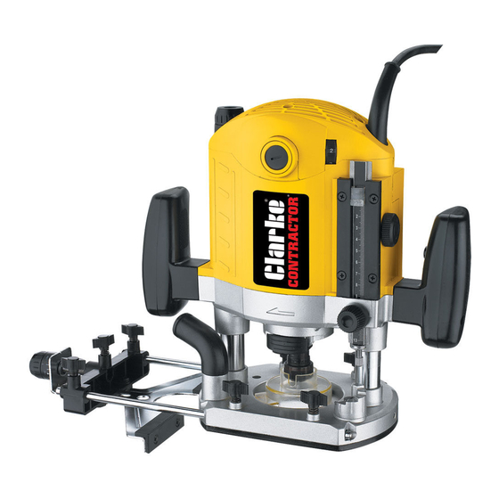
- Page 1 12mm SOFT START ROUTER 12mm SOFT START ROUTER Part No. 6460200 MODEL No. CR2 Part No. 6462075 OPERATING & MAINTENANCE INSTRUCTIONS 0706...
-
Page 2: Specifications
** See Vibration Emission notes on pages 16 and 27 Please note that the details and specifications contained herein, are correct at the time of going to print. However, CLARKE International reserve the right to change specifications at any time without prior notice. CHECK LIST 1 x Carry case. -
Page 3: Table Of Contents
Thank you for purchasing this CLARKE Soft Start Router which is designed for DIY and light industrial use ONLY, for routing wood, wood products and plastic. Before attempting to use the machine, please read this manual thoroughly and follow the instructions carefully. -
Page 4: Safety Precautions For Power Tools
SAFETY PRECAUTIONS WARNING: As with all machinery, there are certain hazards involved with their operation and use. Exercising respect and caution will considerably lessen the risk of personal injury. However, if normal safety precautions are overlooked or ignored, personal injury to the operator or damage to property, may result. ALWAYS learn the machines applications, limitations and the specific potential hazards peculiar to it. -
Page 5: Additional Safety Precautions For Routers
Nails will severely damage the cutter. NOTE : Replacement cutters are available from your CLARKE dealer. WARNING: The use of spare parts or accessories, other than those supplied by CLARKE International or one of its recognised dealers, may be hazardous and could invalidate the guarantee. -
Page 6: Electrical Connections
When using a cable reel, always unwind the cable completely. PARTS & SERVICE CONTACTS For Spare Parts and Service, please contact your nearest dealer, or CLARKE International, on one of the following numbers. PARTS & SERVICE TEL: 020 8988 7400 PARTS & SERVICE FAX: 020 8558 3622 e-mail as follows: PARTS: Parts@clarkeinternational.com... -
Page 7: Assembly Instructions
ASSEMBLY Fig. 1 Note : Always ensure router is isolated from the mains supply, by switching off and removing the plug from the socket. 1. Installing And Changing Router Bits 1.1 Rotate spindle whilst pushing the spindle lock inwards until spindle is locked, (hold lock on). 1.2 Using the wrench supplied, loosen the collet nut a few turns and remove bit if fitted. - Page 8 2. Fitting The Parallel Guide Fig. 2 2.1 Insert the rods into the guide body, securing with the screws provided 2.2 Fit the assembled guide to the Locking Screw router as shown in Fig. 3. 2.3 Secure using the locking screws provided NOTE: The parallel guide allows the user to follow a straight edge with...
-
Page 9: Adjustments
Fig. 5 3.2 Undo and remove the two screws securing the Keep Plate, arrowed in Fig.5. Fig. 6 3.3 Replace the parallel Fence with the Roller Guide, in the manner shown in Fig.6, ensuring it slides neatly and freely on the base. Fig. -
Page 10: Multi-Stop Turret
4. Slacken the Depth Stop Lock Knob and push Fig. 8 the scale down until the Adjuster Rod touches Scale the highest step possible on the turret. Magnifier 5. Line the red line on the scale magnifier with Scale one of the graduations on the scale...zero if Adjuster it is available, then, holding the magnifier steady, wind the scale up, using the scale adjuster, the... -
Page 11: Operation
OPERATION General 1. Always ensure the workpiece is firmly secured. 2. Place router on the workpiece with the cutter in the position to be cut, e.g. cutter just in front of start position - for edge profiling, and the guide firmly pushed up to edge of the work. -
Page 12: Cutter Speeds
Excessive sparking occurs This indicates worn brushes. This problem is quickly remedied but you should consult your CLARKE dealer for parts and advice. Router does not operate when switched ON Check to ensure the fuse is sound and replace if necessary. If the fuse is sound or blows repeatedly, consult your CLARKE dealer. -
Page 13: Parts And Service Contacts
No. Description Qty Part No No. Description Qty Part No Screw M4xl0 HTCR2101 Switch HTCR2234 Base Pad HTCR2102 Plastic Tube HTCR2235 Screw M5xl0 HTCR2103 HTCR2236 Transparent Cover HTCR2104 Tube HTCR2237 Butterfly Screw HTCR2105 C-ring HTCR2238 Tube HTCR2106 Right Handle Cover HTCR2239 Screw M6x12 HTCR2107... -
Page 14: Parts Lists And Diagrams
PARTS DIAGRAM... - Page 15 VIBRATION EMISSIONS HAND-ARM VIBRATION Employers are advised to refer to the HSE publication “Guide for Employers”. All hand held power tools vibrate to some extent, and this vibration is transmitted to the operator via the handle, or hand used to steady the tool. Vibration from about 2 to 1500 herz is potentially damaging and is most hazardous in the range from about 5 to 20 herz.
-
Page 16: Vibration Emission Notes
The graph below shows the vibration value against the maximum time the respective tool may be used, per day. The uncertainty factor should also be taken into account when assessing a risk. The two figures ‘a’ and ‘K’ may be added together and the resultant value used to assess the risk.


Need help?
Do you have a question about the CR2 and is the answer not in the manual?
Questions and answers