
Subscribe to Our Youtube Channel
Related Manuals for Clarke CONTRACTOR CR1C


Summary of Contents for Clarke CONTRACTOR CR1C
- Page 1 1200W VARIABLE SPEED ROUTER MODEL NO: CR1C PART NO: 6462072 OPERATION & MAINTENANCE INSTRUCTIONS 01/11...
-
Page 2: Introduction
INTRODUCTION Thank you for purchasing this CLARKE 1200W Variable Speed Router. Before attempting to use this product, please read this manual thoroughly and follow the instructions carefully. In doing so you will ensure the safety of yourself and that of others around you, and you can look forward to your purchase giving you long and satisfactory service. -
Page 3: Table Of Contents
TABLE OF CONTENTS INTRODUCTION ..............2 GUARANTEE ................2 IN THE BOX ................2 TABLE OF CONTENTS ............3 GENERAL SAFETY RULES ............4 ELECTRICAL CONNECTIONS ..........6 OVERVIEW ................7 BEFORE USE ................8 FITTING THE GUIDES ..............9 USING YOUR ROUTER ............10 ADJUSTMENTS ...............11 ROUTER TIPS ................13 TROUBLESHOOTING ..............13 FITTING YOUR ROUTER TO A ROUTER TABLE ......14 MAINTENANCE ..............15... -
Page 4: General Safety Rules
GENERAL SAFETY RULES WORK AREA Keep the work area clean and well lit. Cluttered and dark areas invite accidents. Do not operate power tools in explosive atmospheres, such as in the presence of flammable liquids, gases or dust. Power tools create sparks which may ignite the dust or fumes. - Page 5 Dress properly. Do not wear loose clothing or jewellery. Keep your hair, clothing and gloves away from moving parts. Loose clothes, jewellery or long hair can be caught in moving parts. POWER TOOL USE AND CARE Do not force the power tool. Use the correct power tool for your application.
-
Page 6: Electrical Connections
ELECTRICAL CONNECTIONS Connect the mains lead to a standard, 230 Volt (50Hz) electrical supply through an approved 13 amp BS 1363 plug, or a suitably fused isolator switch. THIS APPLIANCE IS DOUBLE INSULATED The wires in the mains lead are coloured in accordance with the following code: Blue Neutral... -
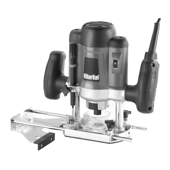
Page 7: Overview
OVERVIEW NO. DESCRIPTION PART NUMBER NO. DESCRIPTION PART NUMBER Speed Dial KPCR1C01 Multi-stop Turret KPCR1C07 Safety Button KPCR1C02 Depth Stop KPCR1C08 Trigger Switch (Rear) KPCR1C03 Depth Stop Lock KPCR1C09 Spindle Lock KPCR1C04 Plunge Lock Lever KPCR1C10 (Rear) Parallel Guide KPCR1C05 Micro Adjustment KPCR1C11 Dial... -
Page 8: Before Use
BEFORE USE WARNING: MAKE SURE THAT THE ROUTER IS SWITCHED OFF AND UNPLUGGED FROM THE MAINS SUPPLY BEFORE FITTING OR REMOVING ANY ACCESSORIES. INSTALLING AND CHANGING ROUTER BITS 1. Rotate spindle whilst pushing the spindle lock inwards until spindle is locked, (hold the spindle lock on). -
Page 9: Fitting The Guides
FITTING THE GUIDES The tool is supplied with three guides, • Parallel fence guide: primarily used for straight cuts, when chamfering or grooving. • Template guide: Fitted when the tool is used in conjunction with templates. • Trammel attachment: Used to move the router in an arc around a selected pivot point. -
Page 10: Using Your Router
FITTING THE TRAMMEL ATTACHMENT 1. Remove one of the rods from the parallel guide and insert it into position on the router. Secure in place using the parallel guide locking screws. 2. Loosen the wing nut on the Screw trammel attachment and slide Wing Nut the attachment on to the parallel guide rod as shown. -
Page 11: Adjustments
2. Press down on both handles to the required depth, pushing the bit into the work piece. • The depth stop should be pre- set (See “Setting The Depth Of Cut” on page 11.) 3. Pull the plunge lock lever towards the handle to lock the body in position. - Page 12 2. Release the plunge lock lever and lower the tool body until the bit just touches the flat surface, then apply the plunge lock. 3. Slacken the depth stop lock and lower the depth stop rod, until the rod touches the multi-stop turret at its lowest setting.
-
Page 13: Router Tips
/ Machine is dirty. holes are clear. Router is overloading. Do not use put excessive pres- sure on the cutter. Excessive sparking. Worn Brushes. Contact you nearest Clarke dealer for repair. Router does not operate Fuse has blown. Replace fuse. when switched on. -
Page 14: Fitting Your Router To A Router Table
A router table may be fitted with a fence, fingerboards and other work- guiding accessories to make the operation safer and more accurate. • We recommend the Clarke CRT1 available from your local Clarke dealer. 1. With the router unplugged, fit the... -
Page 15: Maintenance
MAINTENANCE There are no user serviceable parts in this router, all servicing should be carried out by your nearest Clarke dealer. CLEANING • To ensure the best performance from the router, it must be kept clean. • To reduce fire hazard, keep the cooling vents free of debris. -
Page 16: Specifications
Vibration Levels 6.23m/s Uncertanty value K (1.5) Specifications are correct at the time of going to print. However, CLARKE International reserve the right to change specifications at any time without prior notice. PARTS AND SERVICING There are no user serviceable parts, all servicing and repairs should be carried out by your nearest Clarke dealer. -
Page 17: Vibration Emmisions
VIBRATION EMMISIONS Employers are advised to refer to the HSE publication “Guide for Employers”. All hand held power tools vibrate to some extent, and this vibration is transmitted to the operator via the handle, or hand used to steady the tool. Vibration from about 2 to 1500 herz is potentially damaging and is most hazardous in the range from about 5 to 20 hertz. - Page 18 The graph on the right shows the vibration value against the maximum time the respective tool may be used, per day. The uncertainty factor should also be taken into account when assessing a risk. The two figures ‘a’ and ‘K’ may be added together and the resultant value used to assess the risk.
-
Page 19: Declaration Of Conformity
DECLARATION OF CONFORMITY...
Need help?
Do you have a question about the CONTRACTOR CR1C and is the answer not in the manual?
Questions and answers