Grizzl-E GRS-14-24-P Manual
Hide thumbs
Also See for GRS-14-24-P:
- User manual (29 pages) ,
- User manual & installation manual (30 pages) ,
- User manual and installation manual (28 pages)
Table of Contents
Advertisement
Quick Links
Advertisement
Table of Contents

Related Manuals for Grizzl-E GRS-14-24-P


Summary of Contents for Grizzl-E GRS-14-24-P
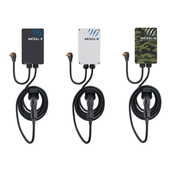
- Page 1 ™ GRIZZL E SMART EV Charger User Manual & Installation Guide...
- Page 2 Grizzl-E Smart Manual Manual Revision: 13.1 Model Numbers: GRS-14-24-P GRS-6-24-P GRS-14-24-AB GRS-14-24-AW GRS-14-24-PC...
- Page 3 The Grizzl-E Smart is the Wi-Fi connected smart EV Charger built from the proven Grizzl-E design. Grizzl-E Smart has Wi-Fi connectivity and can work with any OCPP 1.6 application. It is a simple, powerful, heavy-duty, and portable electric vehicle charging station made in Canada and built to withstand the harshest conditions.
- Page 4 Basic precautions should always be followed when using electrical products, including the following: • Read all the instructions before using this product. • Children should not use this device. • Do not put fingers into the EV connector. • Do not touch live electrical parts. •...
- Page 5 My Charger tab to connect to Wi-Fi and add your charger For more information on how to connect Grizzl-E Smart to a Wi-Fi network see Chapter 8. Set Up Smart Functionality on page 22...
- Page 6 Product Specifications United Chargers GRIZZL-E™ Electric Vehicle Charging Station (EVSE) Description Specifications GRS-14-24-P GRS-14-24-AB GRS-14-24-AW Model Numbers GRS-6-24-P GRS-14-24-PC EVSE Level SAE J1772; AC Level 2 Max Output 40A; 9.6 kW Maximum Output – For use with 50A Circuit Rating Rating 32A;...
-
Page 7: Table Of Contents
7.3 Reset Charger ....................21 8. Set Up Smart Functionality ................22 8.1 Network Requirements ................22 8.2 Connect the Grizzl-E to Wi-Fi ..............22 8.3 Wi-Fi Connection Indicator ............... 23 8.4 Troubleshoot Connection Errors ............. 24 9. Disconnect From Wi-Fi ..................25 9.1 Reset Wi-Fi .................... -
Page 8: Introduction & Unpacking
1. Introduction & Unpacking This user manual applies to the GRIZZL-E™ Smart EVSE for Plug-in Hybrid Electric Vehicles (PHEVs) and Electric Vehicles (EVs). Made in Canada Mounting Bracket (x1) Charging Station with input and output cable (x1) Security Pin (x1) -
Page 9: Installation Planning And Service Wiring
2. Installation Planning and Service Wiring: WARNING: Disconnect the power supply to the charging station before installing, adjusting, or repairing the charging. Failure to do so may result in physical injury or damage to the power supply system and the charging station. CAUTION: To reduce the risk of fire, connect only to a circuit provided with the minimum branch circuit overcurrent protection requirements in accordance with the National Electrical Code ANSI/NFPA 7- and the... -
Page 10: Adjustable Maximum Current Output
3. Adjustable Maximum Current Output The GRIZZL-E Smart charging station features the ability to adjust the maximum Charging Station current output to support 50A, 40A, 30A, or 20A Dedicated Circuit ratings as follows: Circuit Rating Maximum Charging Station Output 40A (9.6 kW) 32A (7.68 kW) - Page 11 CAUTION: The LED pipe is attached to the front cover. When the front cover is removed, place it on a flat surface facing down to avoid damage to the LED pipe. 2. With the front cover placed to the side, locate the DIP switch on the charging station circuit board.
- Page 12 3. Adjust the Maximum Current Output to either 40A, 32A, 24A or 16A, using the following combination of DIP switch settings: Switch 1 Switch 2 Maximum Current Output Switch 3 DIP Switch Setting Switch 4 40A Maximum Current Output DOWN (Factory Default Setting) DOWN DOWN...
-
Page 13: Installation
4. Installation 4.1 Tools & Parts Required for Installation Prior to mounting, determine the location of an acceptable mounting support. All charging station products must be anchored into a mounting support such as a 2” x 4” stud or a solid concrete wall. -
Page 14: Install The Charging Station
4.2 Install the Charging Station 1. Separate the front and back piece of the mounting bracket by pushing down on the notch. Back Piece Front Piece 2. Attach the front piece of the mounting bracket to the back of the charging station using the Socket-cap screws. - Page 15 3. Secure the back piece of the mounting bracket to the wall or other suitable structure using the Robertson-head screws. The back piece of the mounting bracket has 3 holes to support attachment to various surfaces. Use the top two holes to attach the mounting bracket to a wall stud. Mounting Screw Recommendations: •...
- Page 16 4. Mount the charger on the wall by securing the front piece of the mounting bracket to the back piece of the mounting bracket. 5. Secure the charger in place by inserting either the security pin or the outdoor security lock into the mounting bracket.
-
Page 17: Input Wiring Connection (Optional Hardwire Connection)
5. Input Wiring Connection (Optional Hardwire Connection) 1. Choose the appropriate conduit in accordance with all applicable, local, and electrical safety codes and standards. 2. Using the appropriate tool, clamp the ring wire terminal to the copper wire. For non- insulated terminals, use heat shrink tube to cover the non-insulated portion of the terminal. - Page 18 Screw Rating Torque Terminal Conductor 6-8 AWG L1, L2, G 16 lbf/in 75C, copper wire CAUTION: To reduce the risk of fire, connect only to a circuit provided with the appropriate amperes minimum branch circuit overcurrent protection in accordance with the National Electrical Code, ANSI/NFPA 70, and the Canadian Electrical Code, Part I, C22.1.
-
Page 19: Easyevplug Holster And Cable Management System
6. EasyEvPlug Holster and Cable Management System The EasyEVPlug™ Holster or Tesla EasyEVPlug™ Holster is the new innovative method to protect your plug and manage your cord. It has the following features: • No need to aim – flawless plug even in the dark. •... -
Page 20: Charging Status Indicators And Buzzers
7. Charging Status Indicators and Buzzers 7.1 Charging Status Indicators The following Status Indictors will be used: LED Indicator Buzzer Description Definition No Buzzer Not illuminated Power Off No Buzzer Red Steady Initialization Blue + Magenta Charger Ready + No Buzzer Alternating Not Connected to Wi-Fi Blue + Cyan... -
Page 21: Fault Indicators
7.2 Fault Indicators The number of red flashes indicates the type of fault: LED Indicator # of Flashes Error Description Red Flashing Lost ground - AC Line1 Red Flashing GFCI High Leakage Red Flashing Relay is stuck Red Flashing GFCI Low Leakage Red Flashing High temperature of the module... -
Page 22: Set Up Smart Functionality
11. Enter the Wi-Fi Password and confirm the password. 12. Select the Next button. 13. Wait for the app to connect and register the Grizzl-E Smart. Do not close the app or run in the background while the setup process is running. -
Page 23: Wi-Fi Connection Indicator
Grizzl-E will alternate between blue and cyan. If the connection is unsuccessful the Wi-Fi network UC_Smart_[ChargerSerial#] will be visible on devices and the indicator light on the Grizzl-E will alternate between blue and Magenta. Not Connected... -
Page 24: Troubleshoot Connection Errors
Ensure the Wi-Fi Password entered matches the Wi-Fi network settings exactly. Grizzl-E Smart will recycle the connection if password information is incorrect. The password limit for the Grizzl-E Smart is 38 characters. Grizzl-E Smart will not connect to Wi-Fi networks with passwords longer than this limit. -
Page 25: Disconnect From Wi-Fi
9. Disconnect From Wi-Fi 9.1 Reset Wi-Fi If the Grizzl-E Smart Charger is unable to re-establish the connection try resetting the Wi-Fi using the following procedure: 1. Unplug the Charging Station. 2. Remove the front cover by removing the 4 screws at each corner of the charging station. -
Page 26: Change Ocpp Network
1. Follow the instructions in Chapter 9.1 Reset Wi-Fi on page 25 to reset the Wi-Fi board. 2. Follow the directions on Chapter 8.2 Connect the Grizzl-E to your Wi-Fi on page 22 and the third-party Network to configure your charging station with the OCPP central system URL. -
Page 27: Operation
10. Operation 10.1 Connect and Charge Insert the charging Connector into the EV and ensure the connector is fully seated/locked in place. Once complete, the charging session will begin. Charging will start in both Connected Mode (Cyan indicator LED) and Standard Mode (Magenta indicator LED). -
Page 28: General Product Care And Use Information
11. General Product Care and Use Information The exterior of the charging station is designed to be waterproof and dust proof (NEMA 4 Outdoor Rated). However, periodic cleaning may be required, depending on local conditions. To ensure proper maintenance of the charging station, follow these guidelines: •... -
Page 29: Warranty
Chargers shall make the final decision, in fairness to all concerned, as to the legitimacy of any such claim on this warranty. Upon discovery of any defective GRIZZL-E ™, please submit a support ticket to United Chargers technical support for further instructions.
Need help?
Do you have a question about the GRS-14-24-P and is the answer not in the manual?
Questions and answers