Table of Contents
Advertisement
Quick Links
Advertisement
Table of Contents

Related Manuals for Grizzl-E Smart Connect Classic


Summary of Contents for Grizzl-E Smart Connect Classic
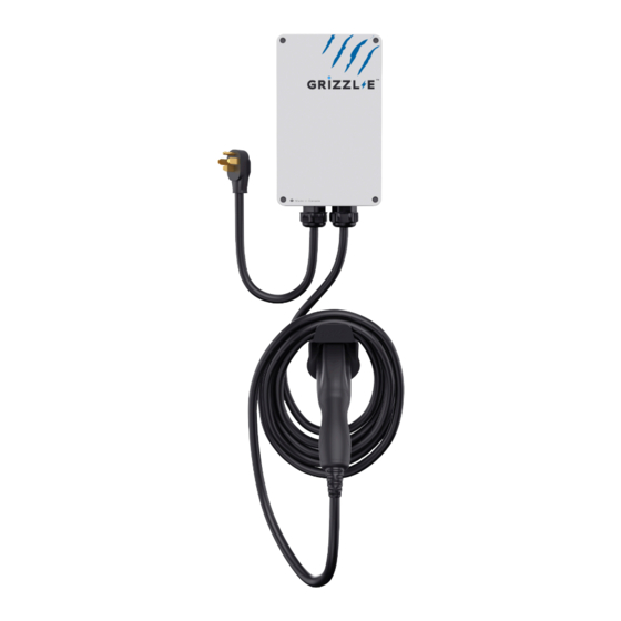
- Page 1 ™ GRIZZL E SMART EV Charger Grizzl-E Connect User Manual & Installation Guide...
- Page 2 Grizzl-E Smart Connect Manual Grizzl-E Smart Connect Version 2: All units manufactured after July 5, 2023*. Manual Revision: 2.0 Model Numbers: Classic Avalanche Edition Extreme Edition GRS-14-24-P GRS-14-24-AB GRS-14-24-PC GRS-6-24-P GRS-6-24-AB *Check the MFG Date on the label. If the MFG date is...
- Page 3 Grizzl-E Smart provides up to 10kW of power to a BEV or PHEV. Maximum current output can be set through DIP Switches to provide 16 Amps, 24 Amps, 32Amps or 40 Amps adjustable maximum current.
- Page 4 Basic precautions should always be followed when using electrical products, including the following: • Read all the instructions before using this product. • Children should not use this device. • Do not put fingers into the EV connector. • Do not touch live electrical parts. •...
- Page 5 Product Specifications Description Specifications GRS-14-24-PB GRS-14-24-AB GRS-14-24-PC Model Numbers GRS-6-24-PB GRS-6-24-AB EVSE Level SAE J1772; AC Level 2 Max Output 40A; 9.6 kW Maximum Output – For use with 50A Circuit Rating Rating 32A; 7.68 kW Maximum Output – For use with 40A Circuit Rating Alternate Adjustable Output 24A;...
-
Page 6: Table Of Contents
7.4 Reset Charger ......................22 8. Set Up Smart Functionality ....................23 8.1 Network Requirements ....................23 8.2 Connect the Grizzl-E to Wi-Fi ..................23 8.3 Change W-Fi Network ....................24 8.4 Troubleshoot Connection Errors ................25 9. Station Wi-Fi Network ......................26 9.1 Change Station Wi-Fi Password ................. -
Page 7: Introduction & Unpacking
1. Introduction & Unpacking 1.1 Your Charger Charger Components 1. Input Cable NEMA 14-50P or NEMA 6-50P 2. Output Cable J1772 Connector 3. Latch Release Button 4. Indicator Light... -
Page 8: Package Contents
1.2 Package Contents Mounting Kit Front Plate Screw (x4) Back Plate Screws (x2) Security Pin (x1) Mounting Bracket (x1) EasyEvPlug Holster Holster Holster Screws (x4) Anchor (x4) Holster (x1) -
Page 9: Installation Planning And Service Wiring
The Charging Stations can connect a Standard NEMA 14-50, NEMA 6-50 Receptacle, or the unit can be hardwired. • It is recommended to use Grizzl-E Chargers with a Circuit Breaker. It is not recommended to use a Fuse Box as this can lead to unexpected blown fuses. 2.2 Grounding Instructions The charging station must be grounded through a permanent wiring system or an equipment grounding conductor. -
Page 10: Adjustable Maximum Current Output
3. Adjustable Maximum Current Output The GRIZZL-E Smart charging station features the ability to adjust the maximum Charging Station current output to support 50A, 40A, 30A, or 20A Dedicated Circuit ratings as follows: Circuit Rating Maximum Charging Station Output 40A (9.6 kW) 32A (7.68 kW) - Page 11 CAUTION: The LED pipe is attached to the front cover. When the front cover is removed, place it on a flat surface facing down to avoid damage to the LED pipe. 2. With the front cover placed to the side, locate the DIP switch on the charging station circuit board.
- Page 12 3. Adjust the Maximum Current Output to either 40A, 32A, 24A or 16A, using the following combination of DIP switch settings: Switch 3 Switch 4 DIP Switch Setting Maximum Current Output Switch 1 Switch 2 40A Maximum Current Output DOWN (Factory Default Setting) DOWN DOWN...
-
Page 13: Installation
4. Installation 4.1 Tools & Parts Required for Installation Prior to mounting, determine the location of an acceptable mounting support. All charging station products must be anchored into a mounting support such as a 2” x 4” stud or a solid concrete wall. -
Page 14: Install The Charging Station
4.2 Install the Charging Station 1. Separate the front and back piece of the mounting bracket by pushing down on the notch. Back Piece Front Piece 2. Attach the front piece of the mounting bracket to the back of the charging station using the Front Plate screws. - Page 15 3. Secure the back piece of the mounting bracket to the wall or other suitable structure using the Back Plate screws. The back piece of the mounting bracket has 3 holes to support attachment to various surfaces. Use the top two holes to attach the mounting bracket to a wall stud. Mounting Screw Recommendations: •...
- Page 16 4. Mount the charger on the wall by securing the front piece of the mounting bracket to the back piece of the mounting bracket. 5. Secure the charger in place by inserting either the security pin or the outdoor security lock into the mounting bracket.
-
Page 17: Wiring Connection
5. Wiring Connection 5.1 Optional Hardwire Connection 1. Choose the appropriate conduit in accordance with all applicable, local, and electrical safety codes and standards. 2. Using the appropriate tool, clamp the ring wire terminal to the copper wire. For non- insulated terminals, use heat shrink tube to cover the non-insulated portion of the terminal. - Page 18 CAUTION: To reduce the risk of fire, connect only to a circuit provided with the appropriate amperes minimum branch circuit overcurrent protection in accordance with the National Electrical Code, ANSI/NFPA 70, and the Canadian Electrical Code, Part I, C22.1. 6. Once the input wiring and conduit are connected, reassemble the charging station. Reinstall the charging station font cover using the following torque force to secure the (4) screws: Screw...
-
Page 19: Replace Output Cable
5.2 Replace Output Cable 1. Remove the front cover by removing the 4 screws at each corner of the charging station. 2. Loosen the gland beneath the charger. 3. Loosen strain relief clamp on inside of charger. Use a screwdriver or other tool to break metal clamp. -
Page 20: Easyevplug Holster And Cable Management System
6. EasyEvPlug Holster and Cable Management System The EasyEVPlug™ Holster or Tesla EasyEVPlug™ Holster is the new innovative method to protect the charging plug and manage the cord. It has the following features: • No need to aim – flawless plug even in the dark. •... -
Page 21: Charging Status Indicators And Buzzers
7. Charging Status Indicators and Buzzers 7.1 Charging Status Indicators The following Status Indictors will be used: LED Indicator Buzzer Description Definition No Buzzer White Steady Initialization Magenta Charger Ready and No Buzzer Steady Not Connected to Server Blue Charger Ready and No Buzzer Steady Connected to Server... -
Page 22: Fault Indicators
7.2 Fault Indicators The number of red flashes indicates the type of fault: LED Indicator # of Flashes Error Description Red Flashing Lost ground - AC Line1 Red Flashing GFCI High Leakage Red Flashing Relay is stuck Red Flashing GFCI Low Leakage Red Flashing High temperature of the module Red Flashing... -
Page 23: Set Up Smart Functionality
8.2 Connect the Grizzl-E to Wi-Fi 1. Ensure charger is powered on and not plugged into the vehicle. 2. Connect to the charger’s Wi-Fi network. The Grizzl-E Smart Wi-Fi network will be the serial number. Example GRS-170000000123. The password for the network is password. -
Page 24: Change W-Fi Network
If the connection is unsuccessful the indicator light on the Grizzl-E will be MAGENTA Not Connected Connected Magenta Blue 8.3 Change W-Fi Network Follow the directions in Chapter 8.2 Connect the Grizzl-E to Wi-Fi on page 23 to change network credentials. Delete credentials for the previous network and insert new network credentials. -
Page 25: Troubleshoot Connection Errors
Ensure a Wi-Fi signal strength greater than −67 dBm or where the charger is located. Check the Wi-Fi signal strength to ensure a quality EV charging experience. Follow the directions in Chapter 8.2 Connect the Grizzl-E to Wi-Fi on page 23 to view the signal strength that the charger is recieving. -
Page 26: Station Wi-Fi Network
Change the Charging Station’s Wi-Fi password for greater security. 1. Ensure charger is powered on and not plugged into the vehicle. 2. Connect to the charger’s Wi-Fi network. The Grizzl-E Smart Wi-Fi network will be the serial number. Example GRS-170000000123. The password for the network is password. -
Page 27: Reset Wi-Fi
8. Replace the enclosure lid by tightening the 4 screws at each corner. 9. Turn on power to the charging station. 10. Follow the instructions from Chapter 8.2 Connect the Grizzl-E to Wi-Fi on page 23 to reconnect to the Wi-Fi network. -
Page 28: Operation
10. Operation 10.1 Connect and Charge 1. Press down on the latch release button. Ensure latch release button is fully compressed. 2. Insert the charging Connector into the EV and ensure the connector is fully seated/locked in place. Once complete, the charging session will begin. Charging will start in both Connected Mode (Blue indicator LED) and Standard Mode (Magenta indicator LED). -
Page 29: General Product Care And Use Information
11. General Product Care and Use Information The exterior of the charging station is designed to be waterproof and dust proof (NEMA 4 Outdoor Rated). However, periodic cleaning may be required, depending on local conditions. To ensure proper maintenance of the charging station, follow these guidelines: •... -
Page 30: Warranty
12. Warranty GRIZZL-E ™ Smart EV Charging Stations 3-Year or 5-Year Replacement Warranty. Grizzl-E comes with the option of a 3-year or 5-year manufacturer’s warranty. This warranty is extended by United Chargers to original purchasers of GRIZZL-E™ EV Charging Stations.
Need help?
Do you have a question about the Smart Connect Classic and is the answer not in the manual?
Questions and answers