Haier QACT17A Installation And Operation Manual
Wired controller
Hide thumbs
Also See for QACT17A:
- Installation and operation manual (63 pages) ,
- Installation and operation manual (63 pages)
Table of Contents
Advertisement
Quick Links
Wired Cont roller
Inst allat ion and Operat ion Manual
QACT17A
Table of Content s
Interface Display .........................................................................1
Icons ..............................................................................................2
Dip Switch ...................................................................................4
Operat ion
Mode Key ....................................................................................6
Fan Key ........................................................................................6
Temperat ure Adjust ment Keys .................................................7
Special Funct ion
Special Funct ion Select ion ..........................................................8
Adjust ECO Parameters ...........................................................10
Child Lock ................................................................................10
Lock Set t ings ............................................................................11
Fahrenheit / Celsius ..................................................................11
Temperat ure Compensat ion ...................................................12
Forced Defrost / Cooling/ Heat ing ............................................12
Error Checks .............................................................................13
Mode Rest rict ion ......................................................................14
Mode Combinat ion Set t ings ....................................................15
Wiring Inst ruct ion .................................................................... 15
49- 5000061 Rev. 6
GEA 08- 21
Advertisement
Chapters
Table of Contents

Related Manuals for Haier QACT17A


Summary of Contents for Haier QACT17A
-
Page 1: Table Of Contents
Wired Cont roller Inst allat ion and Operat ion Manual QACT17A Table of Content s Part s and Funct ions Interface Display .................1 Icons ....................2 Dip Switch ...................4 Operat ion Mode Key ..................6 Fan Key ..................6 Temperat ure Adjust ment Keys ..........7 Special Funct ion Special Funct ion Select ion ............8... -
Page 2: Part S And Funct Ions
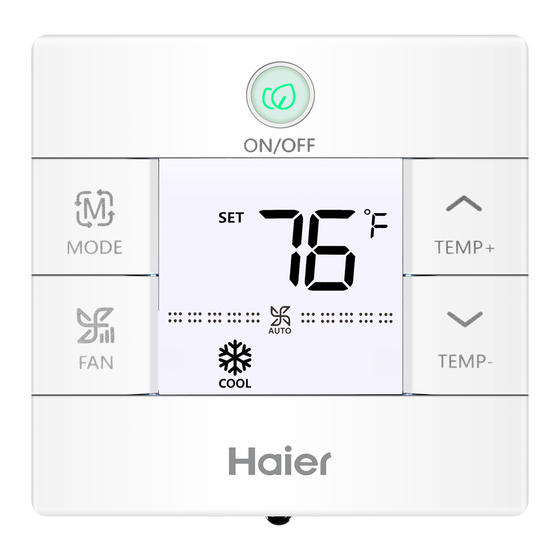
Part s and Funct ions Interface Display MAIN Full Display... -
Page 3: Icons
Part s and Funct ions Icons Room temperat ure display ( dip switch SW1- 2 on). Set temperat ure display Filter HRV (Heat Reclaim Vent ilat ion), if HRV funct ion is set , it will display t his icon Error icon displays detected fault ECO mode on Cent ral/ lock when connected to a cent ral... - Page 4 Part s And Funct ions MAIN / SUB Main / Subordinate wired cont roller Quiet Fan Speed (some models) Low Fan Speed Medium Fan Speed High Fan Speed Turbo Fan Speed (some models) Auto Fan speed is indicated by t he display automat ically stepping from low to high repeatedly.
-
Page 5: Dip Switch
Dip Switch Dip Switch SW1 Default Sw1- 1 Subordinate wired Main wired cont roller cont roller Room temperat ure Sw1- 2 Room temperat ure display on Sw1- 3 Room temperat ure Room temperat ure collected from indoor unit collected from cont roller Auto rest art after power Sw1- 4 power loss... - Page 6 Dip Switch Dip Switch SW2 Default Sw2- 1 Mode Lock Normal Sw2- 2 Tone on st ill sound when command is sent by wireless remote. Sw2- 3 Reserved Reserved Sw2- 4 Reserved Reserved Init ializat ion t he Room Temperat ure display and t he Set Temperat ure display unt il communicat ion is est ablished wit h t he indoor unit .
-
Page 7: Mode Key
Mode Key / Fan Key Mode key: • Each press of t he MODE but ton will change t he operat ing mode • Each mode has it s init ial default fan speed. Mode Fan speed Temperat ure Auto Auto 76°F Cool... -
Page 8: Temperature Adjust Ment Keys
Temperat ure Temperature Adjust ment Keys: • Press t he TEMP+ or TEMP- keys to change t he temperat ure by 1°F increment s. • The temperat ure set point range for Auto, Cooling, Heat ing t hen temperat ure range will change per t he ECO set t ing parameters). -
Page 9: Special Funct Ion Select Ion
Funct ion Select ion Special Funct ion Select ion: Wit h t he cont rol powered on, press and hold t he TEMP+ for 5 seconds to enter t he special funct ion menu. All t he special funct ion icons will display. Use t he TEMP+ and TEMP- but tons to move bet ween icons. - Page 10 Funct ion Select ion...
-
Page 11: Inst Aller Sett Ings
Inst aller Set t ings Adjust ECO Parameters : • Cooling: Power on t he unit . Adjust set temperat ure to 86°F. Press and hold FAN and TEMP+ for 5 seconds. The minimum allowable set temperat ure will be displayed in t he top right corner. -
Page 12: Lock Set T Ings
Lock Set t ings / Fahrenheit Set t ing Cent ral/ Lock Funct ion: Funct ion is act ive only when system has a cent ral cont rol, such as t he YCZ-A004. This set t ing is act ivated only by t he cent ral Cont rol. Cent ral Cont rol Cent ral Lock No funct ions available. -
Page 13: Temperat Ure Compensat Ion
Temperat ure Compensat ion Set Temperature Compensat ion: display will t hen show 0 (default ) or current compensat ion set t ing. Use TEMP+/ - but tons to adjust t he compensat ion. Compensat ion can be set in 1° increment s +/ - 8°F (0.5°C increment s up to +/ - 4°C). -
Page 14: Error Checks
Error Checks How to check error: will display. error history will appear in t he top right corner. The current error will appear in t he middle of t he screen. If t here is no error, “- - ” will display. -
Page 15: Mode Rest Rict Ion
Mode Rest rict ion Mode Rest rict ion Funct ion: • When SW2- 1 is on, t he system mode lock is on. This will lock t he mode to Heat , Cool, Dry or Fan. No but ton press can change mode. -
Page 16: Mode Combinat Ion Set T Ings
Parameter Inquiry: Display Descript ion Value Indoor sensor - Ambient (Tai) Temperat ure °F (°C) Indoor sensor - Vapor (Tc1) Temperat ure °F (°C) Indoor sensor - Liquid (Tc2 Temperat ure °F (°C) Indoor EEV posit ion Half of act ual posit ion Indoor unit address Shown in hexadecimal Indoor unit cent ral address... - Page 17 One Cont roller for up to 16 indoor Indoor N Indoor 15 Indoor 16 Indoor 2 Indoor 1 (main unit ) Wired cont roller Wired cont roller Wired cont roller Wired cont roller Wired cont roller A B C A B C A B C A B C A B C...
- Page 18 Wiring Connect ions 3. Non- MRV Wall Mount (AW...) High Wall ..Unit 0 Unit 1 Unit 15 WK-B (main unit ) A B C A B C A B C W ired cont roller Dipswitch posit ion Dipswitch posit ion Unit # Unit # connect wit h WK- B is considered as...
- Page 19 Wired Cont roller Wiring Inst ruct ion Communicat ion Wiring Wire Size Communicat ion wiring lengt h (m/ ft ) 0.3mm x3- core shielded wire < 100m/ 328ft (22AWG,3wire) 0.5mm x3- core shielded wire (20AWG,3wire) 0.75mm x3- core shielded wire (18AWG,3wire) 1.25mm x3- core shielded wire (16AWG,3wire)
- Page 20 Wired Cont roller Wiring Inst ruct ion Inst allat ion Diagrams 1. To t ake t he front panel and back panel apart , slide t he front panel up and press down on t he back panel. 2. Secure t he back panel to t he wall using screws.
- Page 21 CAN ICES3(A)/ NMB3(A) MANUFACTURER GE Appliances, a Haier Company Appliance Park Louisville, KY 40225 WEBSITE www.Haierduct less.com...
- Page 22 Table des mat ières Composant s et fonct ions Fonct ionnement Fonct ions spéciales Réglages de l’inst allateur...
- Page 23 MAIN Full Display...
- Page 24 Filt re...
- Page 26 Commut ateur DIP Commut ateur DIP SW1...
- Page 27 Dip Switch SW2 Normal Alerte audible...
- Page 28 Touche Mode: • Auto Auto Auto Auto Touche Vent ilateur:...
- Page 29 Touches de réglage de température :...
- Page 32 Réglage des paramèt res ECO Verrouillage pour enfant s :...
- Page 33 Fonct ion Cent rale/ Verrouillage...
- Page 34 Compensat ion de température réglée: Dégivrage forcé : Climat isat ion forcée :...
- Page 36 Fonct ion de rest rict ion de modes :...
- Page 37 Demande de Paramèt re: Réglage de la combinaison de modes: • Polar wire...
- Page 38 • • • • • • • •...
- Page 39 High Wall ..Unit 1 Unit 0 Unit 15 WK-B (main unit ) A B C A B C A B C W ired cont roller Indoor 1 Wired controller A B C Polar wire Polar wire Polar wire A B C A B C Wired controller...
- Page 42 FABRICANT a Haier Company SITE WEB...
- Page 43 Manual de Inst alación y Funcionamiento QACT17A Índice Piezas y Funciones Pant alla de Interfaz ................1 Íconos ....................2 Interruptor DIP ................4 Funcionamiento Tecla de Modo ..................6 Tecla del Vent ilador .................6 Teclas de Ajuste de Temperat ura ...........7 Función Especial Selección de Función Especial ............8...
-
Page 44: Piezas Y Funciones
Piezas y Funciones Pant alla de Interfaz MAIN Full Display... -
Page 45: Íconos
Piezas y Funciones Íconos DIP SW1- 2 encendido). Filt ro falla ECO mode on conect ado a un cont rolador cent ral. Bloqueo para niños... - Page 46 Piezas y Funciones Velocidad de Vent ilación Velocidad de Vent ilación Baja Velocidad de Vent ilación Media Velocidad de Vent ilación Alt a Velocidad de Vent ilación Modo Automát ico Modo de Calefacción Modo de Vent ilación...
-
Page 47: Interruptor Dip
Interruptor DIP ENCENDIDO APAGADO Omisión Sw1- 1 APAGADO principal Pant alla de temperat ura Sw1- 2 Pant alla de temperat ura APAGADO Sw1- 3 recolect ada de la unidad recolect ada del interior cont rolador Sw1- 4 El sistema permanece APAGADO APAGADO elos desarrollados antes... - Page 48 Dip Switch ENCENDIDO APAGADO Omisión Sw2- 1 Bloqueo del Modo Normal APAGADO Sw2- 2 APAGADO Sw2- 3 APAGADO Sw2- 4 APAGADO Inicio unidad interna. Alert a Sonora...
-
Page 49: Funcionamiento Tecla De Modo
Tecla de Modo / Tecla del Vent ilador Modo Temperat ura Automát ico Automát ico 76°F Est ado Alt a 76°F Inicial Calor Automát ico 76°F Vent ilador Bajo Sin pant alla de temperat ura Automát ico 76°F Velocidad de Vent ilación Velocidad de Vent ilación Baja Velocidad de Vent ilación Media Velocidad de Vent ilación Alt a... -
Page 50: Teclas De Ajuste De Temperat Ura
Temperat ura incrementos de 1°F. de ECO). -
Page 51: Función Especial Selección De Función Especial
Selección de Funciones función. - Page 52 Selección de Funciones fut ura)
-
Page 53: Parámet Ros De Ajuste Eco
• • Bloqueo para Niños: aparecerá -... -
Page 54: Fahrenheit / Celsius
cont rol cent ral. Cont rol Cent ral Bloqueo Cent ral • •... -
Page 55: Compensación De Temperat Ura
Compensación de Temperat ura... -
Page 56: Cont Roles De Errores
Cont roles de Errores esquina superior derecha. El error act ual aparecerá en el medio... - Page 58 Monitor Descripción Valor Posición interior EEV Dirección de la unidad interior Dirección cent ral de la unidad interior los modos de funcionamiento omisión. Un cont rol en una parte interna Indoor 1 WK- B Wired cont roller A B C Polar wire A B C A B C...
- Page 59 B: Un cont rolador para hast a 16 partes internas Indoor N Indoor 16 Indoor 2 Indoor 1 Wired cont roller Wired cont roller Wired cont roller Wired cont roller Wired cont roller A B C A B C A B C A B C A B C A B C...
- Page 60 High Wall ..Unit 0 Unit 1 Unit 15 WK-B (main unit ) A B C A B C A B C W ired cont roller Dipswitch posit ion Dipswitch posit ion para conect ar con el WK- B es considerada la unidad maest ra 0.
- Page 61 0.3mm < 100m/ 328ft el cent ro yellow white...
- Page 62 Para separar el panel front al el panel t rasero. usando tornillos. Adhiera el cont rol al panel...
- Page 63 Haier Company www.Haierduct less.com...
Need help?
Do you have a question about the QACT17A and is the answer not in the manual?
Questions and answers