
Related Manuals for INNO Instrument VIEW 730


Summary of Contents for INNO Instrument VIEW 730
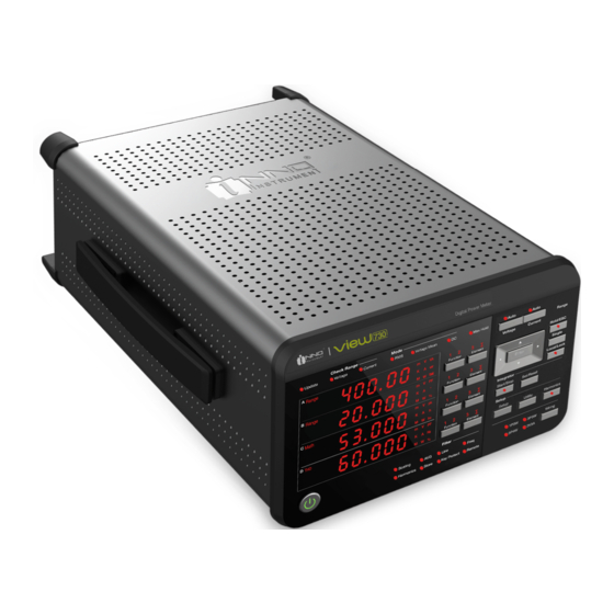
- Page 1 User Manual Please read this Manual carefully before operation Please keep this Manual along with the device VIEW Digtial Power Meter POWERFUL MEASURING INSTRUMENT Ver V1.00...
-
Page 2: Table Of Contents
VIEW Content VIEW 5 Pro Chapter I Name and Use of Components 1.1 Schematic diagram of panel..............................1.2 Brief introduction of key function............................1.3 Character display................................... 1.4 Measurement function display............................. 1.5 Abnormal display of instrument............................Chapter II Before Starting Measurement 2.1 Instructions for Use................................ - Page 3 VIEW Chapter VI Integral Settings 6.1 Integral start & stop................................6.2 Setting of integral mode..............................6.3 Setting of integral timer..............................6.4 Setting of integral D/A timer............................. 6.5 Integral function limitations............................. Chapter VII Storage of Measurement Data 7.1 Turn on/off the storage function............................7.2 Setting of storage interval..............................
-
Page 4: Chapter I Name And Use Of Components
VIEW VIEW 5 Pro Chapter I Name and Use of Components 1.1 Schematic Diagram of Panel ·Measuring channel indicator light Front Panel ·Function switch key ·Unit switch key Navigation key ·Up, down, left and right keys ·Data update indicator light ·OK key ·Voltage and current range warning light Range setting ·Measurement mode state display lamp Automatic range indicator light ·Maximum hold function indicator light Range setting key Other function settings ·Data hold/escape key Display area ·Single measurement key ·Display bar category ·Local control/key lock key ·7-segment digital tube display ·measurement value ·Display measurement function Integral start/stop Integral set/reset Power key Measurement condition setting ·Set key ·Scaling indicator light ·System key... -
Page 5: Brief Introduction Of Key Function
VIEW 1.2 Brief Introduction of Key Function Power key - control the start / close of the instrument It forms the instrument start combination key together with the rocker switch on the rear panel, and the power state indicator light has three effects: The first state is that both the rocker switch and the power key are disconnected, and the power key light is not on, which is equivalent to the uncharged state. - Page 6 VIEW VIEW 5 Pro Navigation key Key name Function specifications Remarks 1. Switch setting options Up and down keys 2. When setting a value, pressing the up key can increase the value, while pressing the down key can decrease the value 1. Move the setting bit of a value to the right (or return to the leftmost from the rightmost) Right key 2. Switch setting items to the right in the menu, such as DA/SET menu 1. Move the setting bit of a value to the left (or return to the leftmost from the rightmost) No decimal point 2. Switch setting items to the left in the menu, such as DA/SET menu Left key 3. Move decimal point position With decimal point (The decimal point moves from left to right, or from the rightmost to the leftmost.) OK key Determine options or perform actions Local / Lock combination key - lock / forcibly disconnect remote connection Function 1: When there is no remote connection, pressing the Local/Lock key for a long time can lock or unlock the key. (Same as Section 9.4) Function 2: When there is remote connection, the remote connection is forcibly disconnected.
-
Page 7: Character Display
VIEW 1.3 Character Display This instrument uses 7 segments of LED display, and numbers, letters and arithmetic symbols are displayed in character strings composed of the following special symbols. The list of contents corresponding to the 7-segment digital tube display is as follows: 1.4 Measurement Function Display Measurement function displayed by each indicator light during routine measurement display Column A indicator light... - Page 8 VIEW VIEW 5 Pro Column C indicator light Display measurement function and description Remarks Display the measured value of the voltage Display the measured value of the current Display the measured value of the current Display the maximum value of the voltage Display the minimum value of the voltage Display the maximum value of current When pressing the "Function" key, the sequence of measurement func- Display the minimum value of current tions displayed in Column C is W→V Display the maximum value of power pk(+)→V pk(-)→A pk(+)→A pk(-)→Wp- Display the minimum value of power k(+)→Wpk(-)→WH→WH±(+)→WH±( -)→AH→AH±(+)→AH±(-)→MATH→V Display the sum of positive and negative watt-hour integrals →A→W, which is displayed cyclically WH± Display positive watt-hour integral value in turn. WH± Display negative watt-hour integral value Display the sum of positive and negative ampere-hour integrals AH± Display positive ampere-hour integral value AH± Display negative ampere-hour integral value Display the measurement items corresponding to the operation MATH...
- Page 9 VIEW Column B indicator light Display measurement function and description Remarks Display the voltage measurement U (K) for the harmonic num- ber shown in Column A Display the current measurement I (K) for the harmonic num- ber shown in Column A Display the active power measurement P (K) for the harmonic number shown in Column A Display the voltage distortion factor UHDF (K) for the harmonic number shown in Column A Display the current distortion factor IHDF (K) for the harmonic number shown in Column A When pressing the "Function" key, the Display the active power distortion factor PHDF (K) for the sequence of measurement functions harmonic number shown in Column A displayed in Column is B V→A→W→V · When the harmonic number displayed in Column A is 1 (fun- and %→A and %→W and %→V damental): the phase angle Ф (K) of the fundamental current and°→A and °→V, which is displayed relative to the fundamental voltage is displayed cyclically in turn. V° · When the harmonic number displayed in Column A is 2~50: the phase angle ФU (k) of the harmonic voltage of the current number relative to the fundamental voltage is displayed. · When the harmonic number displayed in Column A is 1 (fun- damental): the phase angle Ф (K) of the fundamental current relative to the fundamental voltage is displayed A°...
-
Page 10: Abnormal Display Of Instrument
VIEW VIEW 5 Pro 1.5 Abnormal Display of Instrument Data overflow display If the operation value cannot be displayed in the specified decimal point and unit, "--inf--" will be displayed. State description of voltage and current range warning light Color Description Orange Urms or Irms value exceeds 140% of the currently set range... -
Page 11: Chapter Ii Before Starting Measurement
VIEW Chapter II Before Starting Measurement 2.1 Instructions for Use Safety Instructions To ensure that you use this instrument safely and correctly, you shall read the following safety warnings carefully. ● If the instrument is not operated in the correct way, it may cause damage to the instrument. ●... -
Page 12: Turn The Power On/Off
VIEW VIEW 5 Pro 2.3 Turn the Power On / Off Operation when turning on the power As shown in the schematic diagram of the front panel in Section 1.1, the front power switch key and the rocker switch ● on the back of the instrument together form a power double switch design. - Page 13 VIEW Single-phase two-wire system (1P2W), directly input wiring example Load Power supply Power supply Load Input terminal 1 Single-phase three-wire system (1P3W), directly input wiring example Load Power supply Power supply Load Input terminal 1 Input terminal 2 Three-phase three-wire system (3P3W), directly input wiring example Power supply Load Power supply Load Input terminal 1 Input terminal 2 Three-phase three-wire (three-voltage three-current) system 3P3W (3V3A), directly input wiring...
-
Page 14: Measurement Circuit Connecting External Sensor Input
VIEW VIEW 5 Pro Three-phase four-wire (3P4W), directly input wiring example Power supply Load Load Power supply Input terminal 1 Input terminal 2 Input terminal 3 2.5 Measurement Circuit Connecting External Sensor Input When the maximum current of the measurement circuit exceeds the maximum range of the input unit (as described below), an external current sensor can be connected to the current sensor input interface to measure the current. - Page 15 VIEW The connection of shunt current sensor is shown in the figure: When the tested circuit is not grounded, the signal frequency is high or the power is high, the influence of the inductance of the shunt current sensor cable becomes greater. In this case, the measurement is performed using an isolated sensing (CT, DC- CT, or clamp type).
- Page 16 VIEW VIEW 5 Pro Three-phase three-wire system (3P3W), example of wiring by using shunt current sensor Power supply Load Input terminal 1 Input terminal 2 Three-phase three-wire (three-voltage three-current) system 3P3W (3V3A), example of wiring by using shunt current sensor Power supply Load Input terminal 1 Input terminal 2 Input terminal 3 Three-phase four-wire system (3P4W), example of wiring by using shunt current sensor Power supply Load...
- Page 17 VIEW Single-phase three-wire system (1P3W), example of wiring by using transformer (VT/CT) Power supply Load Input terminal 1 Input terminal 2 Three-phase three-wire system (3P3W), example of wiring by using transformer (VT/CT) Power supply Load Input terminal 1 Input terminal 2 Three-phase three-wire (three-voltage three-current) system 3P3W (3V3A), example of wiring by using transformer (VT/CT) Power supply Load...
-
Page 18: Chapter Iii Setting Of Measurement Conditions
VIEW VIEW 5 Pro Chapter III Setting of Measurement Conditions 3.1 Measurement Mode Setting Operating steps 1. Press the Setup key; 2. Select the "Mode" menu; 3. Confirm; 4. Select setting options; 5. Confirm; 6. Exit and close the setting menu. The above operating steps are displayed. -
Page 19: Wiring Mode Setting
VIEW 3.2 Wiring Mode Setting This instrument can be equipped with 1P2W (single-phase two-wire system), 1P3W (single-phase three-wire system), 3P3W (three-phase three-wire system), 3V3A (three-voltage three-current meter method), and 3P4W (three-phase four-wire system) wiring modes. Operating steps 1. Press the Wiring key. 2. -
Page 20: Data Update Rate Setting
VIEW VIEW 5 Pro 1. Press Utility key; 2. Select the "reso" menu; 3. Confirm; 4. Set the number of display digits; 5. Confirm; 6. Exit and close the setting menu. According to the above steps, the switch option "4" or "5" is pressed through navigation (up and down) in the Display Bar C, and "Enter"... -
Page 21: Peak Factor Setting
VIEW 3.5 Peak Factor Setting Under different peak factors, the measurement range options of corresponding voltage, current and external current sensors are different. Operating steps 1. Press Utility key; 2. Select the "cf" setting menu; 3. Confirm; 4. Select peak factor; 5. -
Page 22: Frequency Filter Setting
VIEW VIEW 5 Pro 1. Press the Setup key; 2. Select the "sync" setting menu; 3. Confirm; 4. Select the synchronization source options; 5. Confirm; 6. Exit and close the setting menu. It is operated according to the above steps to enter the synchronization source setting interface. The synchronization source options are located in Display Bar C. -
Page 23: Line Filter Setting
VIEW 1. Press the Setup key; 2. Select the "f.filt" setting menu; 3. Confirm; 4. Set the frequency filter switch; 5. Confirm; 6. Exit and close the setting menu. It is operated according to the above steps to enter the switch setting interface of the frequency filter. The switch options of the frequency filter are located in Display Bar C. -
Page 24: Average Function Setting
VIEW VIEW 5 Pro 3.9 Average Function Setting 3.9.1 Set average function on/off Operating steps 1. Press the Setup key; 2. Select the "avg" setting menu; 3. Confirm; 4. Select average function on/off; 5. Confirm; 6. Exit and close the setting menu. It is operated according to the above steps, the average setting switch options are located in Display Bar C. -
Page 25: Scaling Function Setting
VIEW 1. Press the Setup key; 2. Select the "avg" setting menu; 3. Confirm; 4. Select the average type; 5. Confirm; 6. Select the average type (exponential or linear); 7. Confirm; 8. Set the number of linear averages (8, 16, 32, 64) or the attenuation constant of exponential averages (8, 16, 32, 64); 9. - Page 26 VIEW VIEW 5 Pro It is operated according to the above steps, the scaling setting switch options are located in Display Bar C. Through navigation (up and down) key, ON or OFF of the display scaling can be switched. "ON" or "OFF" option is selected, and the "Enter"...
- Page 27 VIEW 1~7. Same as the operation steps in the previous section; 8. Set VT ratio (display B); 9. Confirm; 10. Set CT ratio (display C); 11. Confirm; 12. Set SF ratio (display D); 13. Confirm; 14. Exit and close the setting menu. It is operated according to the above steps 1 to 7.
-
Page 28: Sensor Conversion Ratio Setting
VIEW VIEW 5 Pro 3.11 Sensor Conversion Ratio Setting 3.11.1 Set independent unit or select all Operating steps 1. Press the Setup key; 2. Select the "ratio" setting menu; 3. Confirm; 4. Confirm; 5. Select the setting unit (select all or independent unit); 6. - Page 29 VIEW 3.11.2 Sensor conversion ratio setting By taking the sensor conversion ratio setting of Unit 3 as an example, the operation method of other units is the same. Operating steps 1~6. Same as the operation steps in the previous section; 7.
-
Page 30: Operation Function Setting
VIEW VIEW 5 Pro 3.12 Operation Function Setting The instrument supports four operation functions, which can be used to display the value of efficiency, peak factor, arithmetic results and average active power. The default setting is efficiency function. 3.12.1 Set operation item Operating steps 1. - Page 31 VIEW When the "Math" function indicator light is on on the left side of Display Bar C, it indicates that the value of the set operation function is displayed in Display Bar C at this time. When displaying the Math function value, the "Element" key operation is invalid, with no unit indication.
- Page 32 VIEW VIEW 5 Pro 3.12.2 Description of operation function Efficiency Definition: The active power P2 measured by Unit 2 is taken as the active power input on the primary side of the converter, and the active powers P1 and P3 measured by Units 1 and 3 are taken as the power consumed on the secondary side of the converter to calculate the efficiency.
-
Page 33: Chapter Iv Range Settings
VIEW Chapter IV Range Settings 4.1 Setting of Voltage Range Operating steps 1. Press the Voltage key; 2. Select the voltage range; 3. Confirm. After pressing the Voltage key, the range options are displayed in Display Bar C and can be switched with navigation (up and down) keys. -
Page 34: Power Range
VIEW VIEW 5 Pro 1. Press the Current key; 2. Select the current range; 3. Confirm. After pressing the Current key, the range options are displayed in Display Bar C and can be switched with navigation (up and down) keys. In the process of setting the current range, the "A" function indicator light on the right side of Display Bar C is on. -
Page 35: Setting Interface Direct Switching Function
VIEW 1. Press the Current key; 2. Select the current sensor option; 3. Confirm; 4. Set the range of external sensor; 5. Confirm. After pressing the Current key, select the "Sensor" option in Display Bar C, and the range options of external current sensor are displayed in Display Bar D and can be switched with navigation (up and down) keys. -
Page 36: Automatic Range Switching
VIEW VIEW 5 Pro 1. Press the Current key; 2. Select the current sensor option; 3. Confirm; 4. Select the direct switching option; 5. Confirm; 6. The same as step 2, you can enter the current range setting interface during direct input. Description Switch the range options in Display Bar C with navigation (up and down) keys, and set the current range during direct input. -
Page 37: Chapter V Harmonic Measurement Settings
VIEW Chapter V Harmonic Measurement Settings 5.1 Turn On / Off the Harmonic Measurement Display Operating steps 1. Press the Harmonics key; 2. Select the display option; 3. Confirm; 4. Set to turn on or off the harmonic display function; 5. -
Page 38: Setting Of Thd Formula
VIEW VIEW 5 Pro 1. Press the Harmonics key; 2. Select the harmonic number setting menu; 3. Confirm; 4. Set the number of harmonic measurement; 5. Confirm; 6. Exit and close the setting menu. Following the above steps 1~3, the number of harmonic measurement will be displayed in Display Bar C. You can set the harmonic number with navigation (up, down, left and right) keys, and then press "Enter"... -
Page 39: Setting Of Pll Source
VIEW 5.4 Setting of PLL Source Set the PLL (Phase Locked Loop) for determining the fundamental frequency; frequency synchronization source, and the fundamental frequency is the reference for the number of harmonic measurements. Selecting the input signal with less distortion or fluctuation as PLL source can make harmonic measurement more stable. Operating steps 1. -
Page 40: Chapter Vi Integral Settings
VIEW VIEW 5 Pro Chapter VI Integral Settings 6.1 Integral Start & Stop Integral start and integral indicator light display Press the Start/Stop key, it flashes and the integral starts. The integral value or average active power (operation function) during integral is displayed in Display Bar C, and the integral time is displayed in Display Bar A. When integral is in progress, press this key again, the key light will stay on, the integral will be paused, and the displayed integral value and integral time will be held. -
Page 41: Setting Of Integral Timer
VIEW 6.3 Setting of Integral Timer Operating steps 1. Press the Set/Reset key; 2. Select the integral timer setting menu; 3. Confirm; 4. Set the hour (Display B); 5. Confirm; 6. Set the minute (Display C); 7. Confirm; 8. Set the second (Display D); 9. -
Page 42: Integral Function Limitations
VIEW VIEW 5 Pro 1. Press the Set/Reset key; 2. Select the integral D/A timer setting menu; 3. Confirm; 4. Set the hour (Display B); 5. Confirm; 6. Set the minute (Display C); 7. Confirm; 8. Set the second (Display D); 9. -
Page 43: Chapter Vii Storage Of Measurement Data
VIEW Chapter VII Storage of Measurement Data 7.1 Turn On / Off the Storage Function Measurement data can be stored. The stored data cannot be called out directly in the display frame of instrument, but can be analyzed by a computer or a connected upper computer through the communication function. Operating steps 1. Press Utility key; 2. Select the "store" setting menu; 3. Confirm; 4. Set the storage function ON/OFF; 5. Confirm; 6. Exit and close the setting menu. Follow the above steps 1~3 to enter the storage setting interface. Switch options "ON", "OFF" and "INTVAL" in Display Bar C, and select "ON"... -
Page 44: Setting Of Storage Interval
VIEW VIEW 5 Pro 7.2 Setting of Storage Interval Operating steps 1. Press Utility key; 2. Select the "store" setting menu; 3. Confirm; 4. Set the storage time interval; 5. Confirm; 6. Set the hour (Display B); 7. Confirm; 8. Set the minute (Display C); 9. -
Page 45: Description Of Storage Function
VIEW 7.3 Description of Storage Function Storage items Storage items include all conventional measurement data, harmonic measurement data (when the harmonic measurement data display is turned on), operation data, integral data and frequency (voltage and current). When the harmonic data display is turned off, the harmonic data will not be stored. When the maximum hold function is turned on, the display values of U (voltage), I (current), P (active power), S (apparent power), Q (reactive power), U+pk/U-pk (voltage peak), I+pk/I-pk (current peak) and P+pk/P-pk (power peak) will hold the maximum values. The stored measurement data also holds the maximum value. When the storage is running, if the "Hold" key is pressed to hold the display, the measurement operation and the storage interval time count will be held (paused), and the data storage will also be held (paused). Press the Hold key again to keep the storage running. Storage limitations When the storage is being executed, the following settings cannot be made: measurement mode, wiring mode, measurement range, peak factor, synchronous source setting, input filter, data update rate, number of harmonic measurement, operational formula of harmonic measurement distortion rate, PLL source setting, storage time interval setting and zero setting. Functions cannot be executed: proportion function setting, average function setting, BIT operation, Math operation function, zero level compensation function, configuration file saving and loading function. -
Page 46: Chapter Viii Network Communication Settings
VIEW VIEW 5 Pro Chapter VIII Network Communication Settings 8.1 Setting of GP-IB Bus The remote control function of the instrument can be realized through GP-IB bus communication. When connecting to PC, it is required to set the address of the instrument in GP-IB system, which is unique and can be set between 1~30. Operating steps 1. Press Utility key; 2. Select the "coon" setting menu; 3. Confirm; 4. Select the GP-IB communication mode; 5. Confirm; 6. Set the address of GP-IB (1~30); 7. -
Page 47: Setting Of Rs-232 Interface
VIEW 8.2 Setting of RS-232 Interface Operating steps 1. Press Utility key; 2. Select the "coon" setting menu; 3. Confirm; 4. Select the RS232 communication mode; 5. Confirm; 6. Set the handshake mode of RS232 communication; 7. Confirm; 8. Set the data format of RS232 communication; 9. - Page 48 VIEW VIEW 5 Pro Configuration description Handshake mode To use RS-232 interface to communicate with PC, the equipment of both sides must negotiate a set of rules to ensure the correct transmission of data. Such negotiation is called a handshake. Since there are many handshake modes between the instrument and PC, it must be ensured that both the instrument and PC shall select the same method.
-
Page 49: Setting Of Usb Bus
VIEW 8.3 Setting of USB Bus Connect the instrument to PC through USB bus to realize remote control between the instrument and PC. Operating steps 1. Press Utility key; 2. Select the "coon" setting menu; 3. Confirm; 4. Select the USB communication mode; 5. Confirm. Follow the above steps and select "USB" in step 4. Press "Enter" key to confirm, and the instrument returns to the previous menu to display. -
Page 50: Setting Of Ethernet
VIEW VIEW 5 Pro 8.4 Setting of Ethernet 8.4.1 Turn on/off the DHCP Operating steps 1. Press Utility key; 2. Select the "coon" setting menu; 3. Confirm; 4. Select the Ethernet communication mode; 5. Confirm; 6. Enter to the Ethernet DHCP setting; 7. - Page 51 VIEW 8.4.2 Setting of Ethernet IP Operating steps 1. Press Utility key; 2. Select the "coon" setting menu; 3. Confirm; 4. Select the Ethernet communication mode; 5. Confirm; 6. Enter to the Ethernet IP address setting; 7. Confirm; 8. Set the first two segments of IP address (Display C); 9.
- Page 52 VIEW VIEW 5 Pro 8.4.3 Setting of gateway Operating steps 1. Press Utility key; 2. Select the "coon" setting menu; 3. Confirm; 4. Select the Ethernet communication mode; 5. Confirm; 6. Enter to the Ethernet gateway address setting; 7.Confirm; 8. Set the first two segments of gateway address (Display C); 9.
- Page 53 VIEW 8.4.4 Setting of subnet mask Operating steps 1. Press Utility key; 2. Select the "coon" setting menu; 3. Confirm; 4. Select the Ethernet communication mode; 5. Confirm; 6. Enter to the Ethernet subnet mask setting; 7. Confirm; 8. Set the first two segments of subnet mask (Display C); 9.
- Page 54 VIEW VIEW 5 Pro 8.4.5 Execution and end of Ethernet Operating steps 1. Press Utility key; 2. Select the "coon" setting menu; 3. Confirm; 4. Select the Ethernet communication mode; 5. Confirm; 6. Select execution of network communication or end of network communication; 7.
-
Page 55: Chapter Ix Other Functions
VIEW Chapter IX Other Functions 9.1 View System Information Viewing steps 1. Press Utility key; 2. Select the "info" menu; 3. Confirm; 4. Select the information to be viewed; 5. Confirm. Follow the above operating steps to enter the information query display interface. Display Bar A displays "INFO" fixedly, Display Bar B displays the information item names, such as "VER", "NO.", "MODEL", "SUFF.1", "SUFF.2"... -
Page 56: Holding Measured Values And Executing A Single Measurement
VIEW VIEW 5 Pro 9.2 Holding Measured Values And Executing a Single Measurement Description of data hold Execute data hold/exit Execute single measuring Description of data hold In the main interface (measured value is displayed), press the "Hold/ESC" key, the "Hold/ESC" key indicator light is on, and the current measured value is held. -
Page 57: Key Lock/Unlock Function
VIEW Operating steps 1. Press the Setup key; 2. Select the "maxhld" function menu; 3. Confirm; 4. Sets to turn on or off the maximum hold function; 5. Confirm; 6. Exit and close the setting menu. Follow the above steps to set whether to turn on the maximum hold function. When the Display Bar C is confirmed as "ON", it means that the maximum hold function is enabled, and the Max hold indicator light on the panel is on. -
Page 58: Initialization Settings
VIEW VIEW 5 Pro 9.5 Initialization Settings The instrument can initialize the setting parameters to return to the factory default. Operating steps 1. Press Utility key; 2. Select the "init" function menu; 3. Confirm; 4. Select whether to execute the initialization operation; 5. Confirm the operation. Follow the above steps to execute initialization, and the instrument immediately returns to the main interface and display the default state after the initialization is completed. -
Page 59: Zero Function
VIEW 1. Press Utility key; 2. Select the "cal" function menu; 3. Confirm; 4. Perform a calibration setting; 5. Confirm the operation. Description of calibration setting function Manual calibration setting Follow the above operating steps to execute calibration setting manually. Automatic calibration function Turn on the instrument, and when the range is changed or initialized manually, the instrument will execute calibration setting automatically. -
Page 60: Bit Function
VIEW VIEW 5 Pro 9.8 BIT Function The system BIT function includes panel key self-check and indicator light self-check. 9.8.1 LED BIT Operating steps 1. Press Utility key; 2. Select the "test" function menu; 3. Confirm; 4. Select LED BIT; 5. -
Page 61: Saving And Loading Of Configuration File
VIEW 1. Press Utility key; 2. Select the "test" function menu; 3. Confirm; 4. Select the key BIT; 5. Confirm; 6. Operate each entity key one by one, and Display C displays the number corresponding to the key in turn; 7. - Page 62 VIEW VIEW 5 Pro Follow the above steps to enter the configuration file saving interface. Display Bar C can be switched to display "File1, File2, File3 and File4", and Display Bar D displays the saving status of the configuration file: "Free" or "Saved". Press "Enter"...
-
Page 63: Setting Of D/A Output
VIEW 9.10 Setting of D/A Output The instrument can output voltage, current, active power, apparent power, reactive power, power factor, phase angle, frequency, voltage peak, current peak and integral value with DC analog voltage of ±5VFS. The system allocates 12 item channels for the output items, and each channel can select to output different measured values. 9.10.1 Selection of fixed output mode Operating steps 1. Press Utility key; 2. Select the "DA" function menu; 3. Confirm; 4. Select the fixed mode of DA output; 5. Confirm; 6. Exit and close the setting menu. Follow the above steps to enter the DA output setting interface, and the instrument has configured two fixed modes for DA output items. - Page 64 VIEW VIEW 5 Pro 2) DFLT-I is the preset integral measured value, and the output item of each channel is fixed as follows Channel Item Channel Item Channel Item CH10 CH11 CH12 NOTE : Among them, P4, WP4 and q4 represent the measured values of the wiring group. 9.10.2 Setting of custom output mode Operating steps...
- Page 65 VIEW 1. Press Utility key; 2. Select the "DA" function menu; 3. Confirm; 4. Select the custom mode of DA output; 5. Confirm; 6. Select the DA output channel 7. Confirm; 8. Set the measurement function of the selected channel; 9.
- Page 66 VIEW VIEW 5 Pro Appendix I Symbols and Definitions of Measurement Function Conventional measurement The panel indicator indicates the unit of measured value and the item being measured. It is on the left or right side of the 7-segment LED screen used for displaying measurement data. Voltage Measurement function Panel indicator lights up...
- Page 67 VIEW Frequency Measurement function Panel indicator lights up Meaning Input unit support Wiring group support (symbol) Voltage frequency Current frequency Integral power (watt-hour) Measurement function Panel indicator lights up Meaning Input unit support Wiring group support (symbol) TIME TIME Integral time Sum of positive and negative watt-hours WP±...
- Page 68 VIEW VIEW 5 Pro Harmonic measurement Harmonic measurement function Measurement function Panel indicator lights up Meaning (symbol) U(K) Effective value of K number of harmonic voltage I(K) Effective value of K number of harmonic current P(K) Active power of K number of harmonics λ(K) Power factor of one harmonics Φ(K) V° or A° Phase difference between fundamental voltage and fundamental current UTHD Total harmonic voltage distortion ITHD Total harmonic current distortion UHDF(K) Harmonic distortion factor of K number of harmonic voltage IHDF(K) Harmonic distortion factor of K number of harmonic current PHDF(K) Harmonic distortion factor of K number of harmonic power Phase difference between K number of harmonic voltage and fundamental ΦU(K) V°...
- Page 69 VIEW Appendix II Initialization Configuration List Item Content Display A Display function: V, input unit: 1 Display function: A, input unit: 1 Display B Display C Display function: W, input unit: 1 Display function: PF, input unit: 1 Display D Display bits 0.5s Data update cycle Zero Line filter Frequency filter Measuring synchronous source Volt (voltage) Auto Current range Voltage range Auto 2V/10V Current sensing range Measuring mode 1P2W Wiring mode Hold Maximum hold Ratio switch: OFF VT: 1.000 Ratio CT: 1.000 SF: 1.000 Sensor conversion ratio switch:OFF ALL: 1000 External sensor conversion ratio...
- Page 70 The End * Products models and specifications are subject to change without prior notice.
- Page 71 Homepage Copyright ⓒ 2021 INNO Instrument Inc. All rights reserved. www.innoinstrument.com E-22F, 30, Songdomirae-ro, Yeonsu-gu, Incheon 21990, Republic of Korea Please visit us on Facebook tel 82-32-837-5600 fax 82-32-837-5601 www.facebook.com/innoinstrument...
Need help?
Do you have a question about the VIEW 730 and is the answer not in the manual?
Questions and answers