
Related Manuals for INNO Instrument VIEW600


Summary of Contents for INNO Instrument VIEW600
- Page 1 VIEW600 User’s Manual Please read this user manual before using the device. Please keep this manual together with the device. 2018/09 0.06...
- Page 3 VIEW600 User’s Manual...
- Page 5 2018, INNO INSTRUMENT, INC. ⓒ All rights reserved. This manual is only subject to the users who purchased this product (View600). No part of this manual can be reproduced without any prior written permission from the publisher. INNO INSTRUMENT, INC Address::E-22F,30,Songdomirae-ro,Yeonsu-gu,Incheon21990, Republic of...
-
Page 6: Table Of Contents
Contents Preface Chapter 1: Overview Introduction Basic function OTDR test VFL/LS module Fiber microscope (Fiber Inspection Probe) module OPM module Basic configuration Power supply Size and weight Environment condition Chapter 2: Installation Safety warning and precautionary measures Operation warnings Transportation and storage Appearance overview Front panel The upper connection panel... - Page 7 Adjust the backlight brightness Software upgrading File copy Chapter 4: OTDR Module Move cursor key Move trace key Partial amplification key “1:1” trace recovery key Shortcut key for trace amplification Shortcut key for trace shrink Full screen display key Parameter setting key OTDR key Event key Measurement key...
- Page 8 Display screenshot key Chapter 5: SOLA “SOLA” operation Start/ Stop Save/Open Management Identification Line definition (Link info) Line pass Element pass Settings Make report Save as Screenshot Chapter 6: Optical Power Meter Overview OPM Operation Chapter 7: VFL and Light Source Overview Visual light source operation light source operation...
- Page 9 Standby and brightness Time Language WI-FI Printer System maintenance Chapter 11: System Information System information Appendix Structure requirement Hardware interface requirement Software interface requirement Operating environment requirement Performance requirement Term list Maintain and technical support VIEW600 OTDR Module Contents Contents...
-
Page 10: Preface
Preface Safety symbols To prevent personal injury and property damage from the misuse of the device, INNO Instrument uses the following safety symbols to show relevant information. Before using the device, make sure that you understand the meaning of these symbols. - Page 11 Laser Safety Label COMPLIES WITH FDA RADIATION PERFORMANCE STANDARDS, 21 CFR SUBCHAPTER J. Caution: This device complies with Part 15 of the FCC Rules / Innovation, Science and Economic Development Canada’s licence-exempt RSS(s). Operation is subject to the following two conditions: (1) this device may not cause harmful interference. (2) this device must accept any interference received, including interference that may cause undesired operation.
- Page 12 If it exceeds the service life and needs to be replaced, please contact with technical person for replacement. External storage: The USB and SD card are used as external storage to preserve data for this product. INNO Instrument (China) Inc. is not responsible for the loss of data. Preface...
-
Page 13: Chapter 1: Overview
Introduction High-performance hardware and wieldy software used in View600 can shorten the process of installation, debugging and fiber distance maintenance. This chapter will describe the features and basic operations of VIEW600 OTDR test unit. Basic function View600 is mainly used for fiber fault diagnosis, especially in FTTH application. -
Page 14: Vfl/Ls Module
Light source LS (Stable light source) Light source with different wavelengths (i.e. 1310/1550/1625nm) and multiple signal modulation modes in-built in View600 are able to satisfy demands in actual applications, as shown in the following picture. Chapter 1 Chapter 1... -
Page 15: Fiber Microscope (Fiber Inspection Probe) Module
Fiber microscope (Fiber Inspection Probe) module The grind quality and cleanliness of optical connector can be detected by being connected external fiber inspection device to USB port. OPM module The optical power meter is used to measure absolute optical power meter or rela- tive optical power loss through a span of optical fiber. -
Page 16: Size And Weight
Size and weight Size: 218 x 159 x 70 mm • Weight: 1.84Kg (without battery) / 0.36kg (with battery) • Environment condition Operating environment: Altitude: 0 to 5000m, Temperature: -20℃ to 60℃, • Relative humidity: 0% to 95%, Max. wind velocity: 15m/s Storage environment: temperature: -10℃... -
Page 17: Chapter 2: Installation
Installation Safety warning and precautionary measures It is very important that VIEW600 is designed for fiber optical testing, not applied for any other purpose. Since OTDR is high precision machine, it should be seri- ously carried. Please strictly comply with the following safety rules and general specifications when you use and carry it. -
Page 18: Transportation And Storage
power supply will lead to fumes, electric shock or facility damage; even it will result in fire accident, body hurt and death. Please only use exclusive AC power cord. Weighty items should not be placed • on the power line, please not let power line heated or change the power line. Inappropriate or damaged power line will lead to fumes, electric shock and facility damage;... -
Page 19: Front Panel
Home menu The upper connect panel Port description DC power connector Connect the adapter. SMF port(Testing VIEW600 testing interface, applied in OTDR and light source modules of port) VIEW600. VFL port Visual light source port. USB port Connect USB storage device / fiber end probe. -
Page 20: Charging Method
The test port lies on the upper panel of the main body. There are two or three test ports on view600. The type of the test port connected by optical fiber depends on the testing application, while the number of the test port depends on the mea- sured wavelength. -
Page 21: Connection Test
Use compressed air to blow-dry the top of the connecting bar. • Options: Turn off VIEW600. Observe the top of connecting bar by fiber inspec- • tion scope. Top of the contaminated Top of the cleaned connecting bar... -
Page 22: Connect Fiber Inspection Probe (Fiber Microscope)
Insert the fiber jumper to the connector of VFL port. • Connect fiber inspection probe (fiber microscope) Connect with external fiber end inspection probe from USB interface. Follows are the process to connect the visual light source: Open the cover of USB port. •... -
Page 23: Chapter 3: Basic Operation
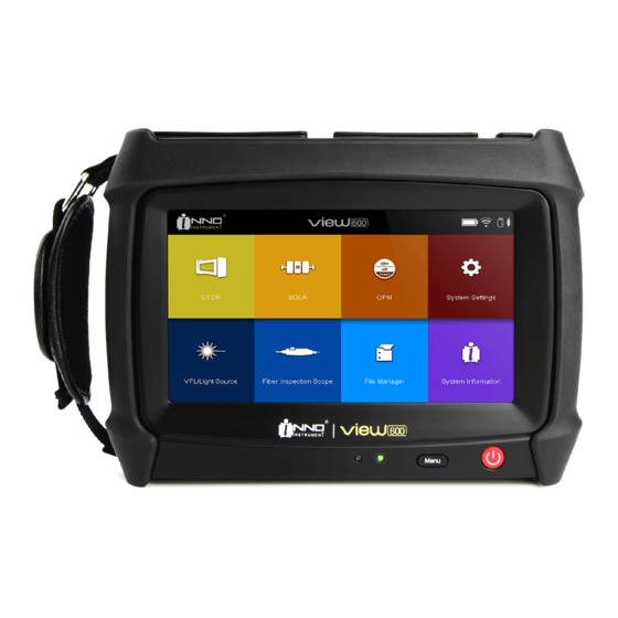
Starting up: Press and hold the power key until the green indicator illuminates on and the logo of INNO Company appears on VIEW600 screen, and then you can access to the following main menu, as shown in the following picture. -
Page 24: Software Upgrading
Software upgrading Please refer to 10.3.5 for detail information. File copy As the following picture shows, after inserting external storage device, you can check the path of external storage device it in file management interface, and then you can enable functions such as Copy, Paste and Delete. Chapter 3 Chapter 2 Basic Operation... -
Page 25: Chapter 4: Otdr Module
OTDR Module The modules used in this device are interchangeable as needed. The OTDR module should be loaded at first before OTDR function is enabled. If not, a pop-up message will appear on the screen, as shown in the following picture: After loading OTDR and turn on the device, please click OTDR icon on the home screen to enable OTDR function. - Page 26 1. Move cursor key 12. Home key 2. Move trace key 13. Nextλ key 3. Partial amplification key 14. Save as key 4. “1:1” trace recovery key 15. Create report key 5. Shortcut key for Trace amplification 16. OTDR setting key 6.
-
Page 27: Move Cursor Key
Move cursor key After Clicking the Move cursor key, you can change the position of the cursor on the screen by touching on the trace. Move cursor key Move trace key Click the key for trace moving; you can move the amplified trace by touching on the screen. -
Page 28: Partial Amplification Key
Partial amplification key Click “partial amplification” key and then click the screen to select the area of trace displayed. This area will be amplified and displayed on “trace display small screen interface”. Partial amplification key “1:1” trace recovery key As shown in the following picture, after zooming in or out the trace, click “1:1” trace recovery key to reset the trace. -
Page 29: Shortcut Key For Trace Amplification
Shortcut key for trace amplification Click the “Move cursor” key or “Move trace” key and then click the “Trace ampli- fication” shortcut key to zoom in the trace horizontally. (Picture1) Click the “Partial amplification” key and then click the “Trace amplification” shortcut key to zoom in the trace vertically. -
Page 30: Parameter Setting Key
The OTDR menu is shown as follows: The Event menu is shown as follows: The Measurement menu is shown as follows: The Trace Info menu is shown as follows: Parameter setting key The wavelength, distance range, pulse width and average time can be set on the interface of measurement parameter setting. -
Page 31: Otdr Key
OTDR key As shown in the picture, click “OTDR” to enter into OTDR measurement setting interface. Event key As shown in the picture, enter into the event interface by clicking “Event” key. The information of events such as Type, Number, Location, Loss, Reflectance, Attenuation and cumulative loss (Sum) can be shown. - Page 32 2)The purpose of changing the event point is to view the specified measured data in detail by taping the arrow keys left or right. 3)“Add” is used to insert event point in the selected position on the trace. 4)“Delete” is used to delete the inserted event point. 5)“Maximize”...
-
Page 33: Measurement Key
Both reflective and non-reflective event can cause event loss. There are two algorithms on View600. Click “Loss” key to switch between the two algorithms. Loss:1. Four points event loss:Event Loss can be computed by LSA. The loss displayed in event lists can be computed by 4 point method. -
Page 34: Attenuation
Attenuation Click “Measurement” key and then select “Attenuation” key. The attenuation measured in two points refers to the RBS attenuation given by the distance function between 2 points (as per the fiber standard, it is labeled as dB/km). Only use these 2 points to calculate but there is no need to gain average value. -
Page 35: Optical Return Loss
Note: in real-time mode, the value of the reflectance may not be always ac- curate. Optical Return Loss ORL calculation: 1) ORL between marker line A and marker line B. 2) Total ORL between start point of fiber span and the end point of fiber span. (Only the ORL of the single mode fiber can be calculated. -
Page 36: Trace Information Key
Trace information key As shown in the following pictures, enter the trace information interface by clicking “Trace info”. On page one display the measured data at a wavelength, while on page two display the measurement parameter setup at a wavelength. Picture 1 Picture 2 The interface of trace information will show basic information about the measured... - Page 37 Save file There are functions such as “Save trace”, “Save to” “Auto naming” “Identification” and “Clear trace” in the “Save file” menu. Save trace As the following picture shows, the selected trace can be saved if “Save trace” icon is clicked. Save to You can click “Save to”...
- Page 38 Auto naming Enter the “Auto naming” menu from the “Save file” menu after selecting “Auto naming” key. And then you can set the file name, file format and the modes of sorting files. Picture 1 Picture 2 Identification Enter the “Identification” menu from the “Save file” menu after selecting “Identifica- tion”...
-
Page 39: Otdr Setting Key
Clear trace As shown in the following pictures, the trace can be cleared if “Clear trace” icon is clicked. Picture 1 Picture 2 Open file As shown in the picture, click “open file”, select the file and then click “Open” to open the file. -
Page 40: Common Setting
Common Setting “Common” is used to set “loss measure method”, “attenuation measure method”, “application option”, “display option” and “Path of the file to be saved”. Please refer to the following picture. Introduction to the measuring methods: TPA: Four points event loss:Event Loss can be computed by LSA. The loss dis- played in event lists can be computed by 4 point method. - Page 41 Introduction of the display option: 1) Screenshot button: Sets whether to display the screenshot button at the bot- tom right of the OTDR screen. 2) File name: Sets whether to display the file name for the active trace appearing on the OTDR menu. 3) Cursor distance: Sets whether to display the cursor locations at the upper left of the OTDR and Event menus where traces are displayed.
-
Page 42: Sample Setting
3)Unit Conversion: 3 types of unit are available on View600, i.e. m/km 、yd/ mile ft/kft 3.Fiber Set: To set the IOR, Backscattering (dB), Excess Length (%). Different numerical results can be obtained after analysis according to different settings.(... -
Page 43: Analysis Set
Analysis Set “Analysis set” is used to set the parameter of analysis trace. 1) Splice Loss Threshold (dB): To analyze the small non-reflective event on trance. 2) Return Loss Threshold (dB): To analyze the small reflective event on trance. 3) Fiber End Loss Threshold (dB): To analyze the important even loss on trance. All these types of loss will affect the signal transmission. -
Page 44: Custom Setting
Custom Setting Custom range: You can set the measurement distance as needed. And the values of the distance you have defined can revert to the default values immediately when you click “Default” key. User-definable range Picture 1 Picture 2 Custom time: You can set the measurement time as needed. And the values of the time you have defined can revert to the default values immediately when you click “Default”... -
Page 45: Create Report Key
Create report key As shown in the following picture, click “Create report” and then click the confir- mation key in the popup message. Until message indicating file creating success pops up, you can find that a piece of PDF file has been created in the default directory. -
Page 46: Next Λ Key
Next λ key On the premise of obtaining two traces during dual-wavelength testing, as shown on the picture, you can click “Next λ” to switch the trace and its information.the file name, file format, or select the file to the USB. Picture 1 Picture 2 Return key... -
Page 47: Main Menu Key
Main menu key (Home) If you want to return to the main menu interface in different function modules, click main “Home” key to fast return to the main menu interface, then operate other modules. Display screenshot key As shown on picture1, “Display screenshot” can be enabled to display the com- plete trace to facilitate customer’s macroscopic observation to the trace. -
Page 48: Chapter 5: Sola
After module is selected and loaded, turn on the device and then click “SOLA” icon on VIEW600 main interface to enable the SOLA function.(the SOLA perfor- mance will vary depending on the module changed)... -
Page 49: Start/ Stop
SOLA menu The Line loss and Return Loss for each measurement with each wavelength on the optical fiber link will be shown on the SOLA interface. Line loss: It refers to the total loss of the fiber link measured. Return Loss: it refers to the ORL on the whole fiber link. Start/ Stop You can click “Start”... -
Page 50: Save/Open
Save/Open You can save and read the measured trace in the “Save/Open” menu. Enter the “Save/Open” menu by clicking the “Save” key, as shown in the following picture. Save SOLA Save the trace of SOLA file format to the default directory. Save to USB Save the file to the USB. - Page 51 You can select the directory as needed by clicking “Top directory” or “Root path”. Auto Naming You can change name of the file and select PDF report and SOLA as a file format. Clear SOLA If you click the “Clear SOLA”, the file name and trace displayed will be cleared together.
-
Page 52: Management
Management As shown in the picture, you can enable “management” function by tapping on “setup” key to set related measuring parameters such as “identification(identify)”, “link definition(line define)”, “link pass(line pass)”, “element pass(item pass)”. Identification If you enter the Identification menu by clicking “Manage”, the corresponding records of the files saved after SOLA measurement can be shown. -
Page 53: Line Pass
Line Pass You can modify related numeric, including adjusting the conditions of measure- ment link and the thresholds of pass/failed. Element Pass You can modify the related thresholds to judge whether the elements are passed or failed. For example: When you want to modify max splice loss, directly click the value in intersection, and then you will see a pop-up box for value input on the screen (Relative message will be shown when the value entered exceeds the limit.) When you select “apply to all wavelengths”, the list of values will be applied in all... -
Page 54: Settings
Settings In the Settings menu of SOLA, you can select the wavelength, and set the lengths of Launch Fiber and Receive Fiber, as shown in the following picture. Make report Select the “make report” tab to save the current SOLA file in PDF format. Save as You can click the “Save as”... -
Page 55: Screenshot
Screenshot The displayed image can be captured via the screenshot key in the SOLA menu. Chapter 5 SOLA Chapter 7 VFL and Light Source... -
Page 56: Chapter 6: Optical Power Meter
Optical Power Meter Overview The optical power meter of high accuracy is used to measure absolute optical power meter or relative optical power loss through a span of optical fiber. This module can measure optical power of multi-wavelength. It can be operated easily. OPM Operation Connect the light source to OPM port with a fiber jumper connector. -
Page 57: Chapter 7: Vfl And Light Source
VFL and Light Source Overview The types of source of VIEW600 include visual light source and light source. Visual light source (VFL) Visual light source equipped in View600 can offer visualization method for fiber fault location. The red light from visual light source can be captured by human eyes, being able to identify direct fault location in fiber test dead zone or make fiber core calibration in multi-fiber cable. -
Page 58: Visual Light Source Operation
The light source module can provide invisible light source(the wavelength and power depend on the type of module selected) and the types of light include CW light, 1KHZ light, 2KHZ light ,1KHZ blink light ,2KHZ blink light. Visual light source operation Connect the tested fiber to the port of optical source. - Page 59 Turn off “light source”: please tap on “close” key on the right side. • Warning: The eyes’ focusing on VIEW600 light source or the fiber end connected to light source is forbidden, which may cause damage to eyes. Chapter 7...
-
Page 60: Chapter 8: Fiber Microscope
Overview The grind quality and cleanliness of the fiber connecting end face can be inspected with the aid of the magnified surface view displayed on the screen of VIEW600. Start fiber end inspection After connecting the fiber inspection probe, click “Fiber Microscope” on VIEW600 main interface to enter into the inspection interface. -
Page 61: The Function Of Fiber Microscope
The function of fiber microscope The functions of the fiber inspection probe (fiber microscope) include “screenshot/ real time (video)”, “open”, “save”, “Align center”, “Zoom”, “save report”, “Result” and “identification”. “screenshot/real time (video)” function is a premise of “save”. After connecting •... -
Page 62: Check The Preserved Image
“Identify” function is used to set related information displayed, the contents of • which are user-definable. Check the preserved image Click the file management icon on the main interface. • Select the image saved path (the saving path for VIEW600 is set to be: sdcard\ • Fiber_Microscope). Chapter 8 Fiber Microscope... -
Page 63: Chapter 9: File Management
VIEW600 are sdcar and usb). Start file management Click “File Manager” on main interface of VIEW600 to enter into the file menu. File manager function There are following items in this menu, such as File Name, Date, and Types of File. - Page 64 “Operate” Function There are functions of “copy”, “paste”, “delete”, “rename”, “Send to USB”, and “create folder” and “remove USB” included in operation interface. • COPY/PASTE key Select one file and then click Copy to copy one file. Or, if users need to select all the files to copy all of them, just select the box after the File Type.
- Page 65 • DELETE key It can delete the files or subdirectory in the directory. Operation steps: a. Click FILE TYPE to select the file type needed to be deleted b. Click and access to the root directory (sdcard /usb) c. Select folder or files to execute DELETE •...
- Page 66 • SEND TO USB key The key of Send To USB is used to send the files or folders selected to the USB. • CREATE FOLDER key It can create a subfolder under the current folder. Operation steps: a. click and access to the root directory (sdcard /USB directory) b.
-
Page 67: System Settings
System setting Overview The system setup function that VIEW600 has offered can let the user modify the system parameters as required. System setting Click “Setting” on the main interface of VIEW600 to enter into the “system setup” interface. Functions of system settings There are functions such as “standby and brightness”, “time”, “language”, “WIFI”, “... -
Page 68: Time
Time You can use “time” function to set the time that is displayed on the device. Language The “language” function is used to set the languages displayed on the screen. You can select “Import Profile” to configure the multi-languages by the PC. Chapter 10 System setting... -
Page 69: Wi-Fi
WI-FI “Wi-Fi” function can be used to connect the device to local area network (LAN), realizing wireless internet. Under this function, along with upper computer, wireless file transmission can be realized. (Please refer to the Wi-Fi Instruction for the usage in detail.) Printer You can enable the default printing function after you select the “Printer”... -
Page 70: System Maintenance
“factory reset”. Please refer to picture. “Software upgrade” can be used for the software upgrade and degradation. • Operation steps: Insert the USB with file to be updated and power adapter to VIEW600 port • respectively. Click “System maintain” on system setup interface. -
Page 71: Chapter 11: System Information
System Information System information As shown in picture, this interface displays the information about the products and manufacturer. If you select to pay by installment, the corresponding information will appear on the screen and you can also access to the “Ultimate key” menu. 图... -
Page 72: Appendix
Appendix Structure requirement Display screen: 7inch (800 x 480) • Indicator light (2 pieces) • Indicator light State Function Long-time onlight Full charged 2Hz blink Adapter power supply Charge light (Red) 1Hz blink Battery charge Take out the adapter, battery power supply. Long-time on light Starting up operation Power light... -
Page 73: Software Interface Requirement
Software interface requirement Interface mode: button input or touch screen input • Operating platform: Linux 2.6 • Operating environment requirement Temperature requirement: • Working temperature: -10℃ ~ 50℃ Storage temperature: -20℃ ~ 60℃ • Humidity requirement: (general standard) Operating humidity: 0% ~ 45%, non -condensation Storage humidity: 0% ~ 95%, non -condensation Performance requirement Module... -
Page 74: Term List
Term list This term list gives explanations about fiber and related devices. Backscattering: The scattered light which opposes to the previous direction of • propagation. Bandwidth: The function size transmitted by waveguide drop 3db below the zero • frequency. The lowest frequency bandwidth is the function of waveguide length, but it is not in direct proportion to the length. - Page 75 Fiber core: The central area where light propagates through it. Fiber core ec- • centricity ratio: The core center displacement measurement relative to the cladding center. Fiber core ellipticity: The deflected measurement for aspheric fiber core and • perfect circle. Insertion loss: Due to the insertion of optical module ( the connector or coupler in •...
- Page 76 OTDR: OTDR transmit impulse to fiber to measure backscattering. Through • analysis the track can determine the event. Optical Time Domain Reflectometer (OTDR): A kind of device used to measure • the optical features in optical pulse transmission, and make measurement of the back scattering light and reflected light as the time function.
- Page 77 Transmitter: A kind of driver can switch electric signal to optical signal. • Transmission loss: Total loss in system when transmission happens. • Telecom cabinet (TC): It is an enclosure space placed by cross-linked fiber • terminal and telecom settings. Equipment cabinet is regarded ascross-link by main wiring and horizontal wiring.
-
Page 78: Maintain And Technical Support
Maintain and technical support Any operation, such as calibration, maintenance or repair of the device can only be carried out by qualified maintenance technicians. Please contact the engineers of INNO Instrument. You can also consult any question through the following website. www.innoinstrument.com Tel: +82-31-742-8755 Fax: +82-31-742-8799... -
Page 79: View600 Otdr Module
VIEW 600 OTDR Module OTDR VIEW610-1 VIEW610-2 VIEW610-3 VIEW620-1 VIEW620-2 VIEW620-3 1310/1550/ 1310/1550/ 1310/1550/ 1310/1550 nm 1310/1550 nm 850/1300 nm 1625nm 1625nm live port 1625nm live port Dynamic Range 30/28 dB 30/28/28 dB 30/28/28 dB 36/35 dB 36/35/35 dB 27/29 dB Distance Range 1.3,2.5, 5, 10, 20, 40, 80,120, 160, 360 KM 3ns,5ns,10ns,30ns,50ns,100ns,200ns,300ns,500ns,... - Page 80 The End Product specifications and models are subject to change without notice.
Need help?
Do you have a question about the VIEW600 and is the answer not in the manual?
Questions and answers