
Related Manuals for INNO Instrument 5G SMART


Summary of Contents for INNO Instrument 5G SMART
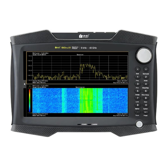
- Page 1 R1.3 5G SMART / 5G PRO Handheld Spectrum Analyzer USER GUIDE 5G SMART : 9 kHz to 15 GHz 5G PRO : 9 kHz to 43 GHz INNO INSTRUMENT INC.
-
Page 2: Table Of Contents
Configuring Network ..........................19 File Manager ............................19 Updating Firmware ..........................20 Instrument Functions ..........................21 Changing Center Frequency and Span ....................21 Change Reference Level .......................... 21 Changing Sweep Time ..........................21 R1.3 5G SMART & 5G PRO SPECTRUM ANAYZER USER GUIDE... - Page 3 Setting Start and Stop Frequency ......................38 Setting Reference Level .......................... 38 Setting Attenuation ..........................39 Using Preamplifier ........................... 39 Changing Sweep Time ..........................39 Setting Resolution Bandwidths ....................... 40 Setting Detector ............................41 R1.3 5G SMART & 5G PRO SPECTRUM ANAYZER USER GUIDE...
- Page 4 Configuring 5GNR Demodulation Measurement ..................55 Measuring 5GNR Multi Beam ......................... 56 Measuring 5GNR Single Beam ........................ 56 Upgrading Software License ........................57 Checking a License Information ......................57 Importing Software License ........................57 R1.3 5G SMART & 5G PRO SPECTRUM ANAYZER USER GUIDE...
-
Page 5: Safety Instruction For Rechargeable Lithium-Ion Battery
Keep the batteries clean and dry. If the terminals become soiled, clean them with a dry, clean cloth. Charge the batteries prior to using them. Only use the appropriate INNO Instrument charger provided with the instrument to charge the batteries. If the batteries are improperly charged, there is a risk of explosion, which can cause serious personal injury. - Page 6 This INNO Instrument’s product is warranted against defects in material and workmanship for a period of three years from the date of shipment. During the warranty period, INNO Instrument will, at its option, either repair or replace products that prove to be defective.
-
Page 7: Getting Started
Slide batery cover to open posi�on located on the batery compartment. Open the cover. Insert the provided batery into the Spectrum Analyzer. Close the cover and slide cover to close posi�on. R1.3 5G SMART & 5G PRO SPECTRUM ANAYZER USER GUIDE... -
Page 8: Using Ac Adapter
Risk of instrument damage. To avoid instrument damage, Only use the power supply (INNO Instrument, ADP-65JH BBFC) included in the package. Make sure that the AC supply voltage is compatible to the voltage specified on the power supply unit. -
Page 9: Instrument Overview
INSTRUMENT OVERVIEW 5G SMART (9 kHz ~ 15 GHz) 5G PRO (9 kHz ~ 43 GHz) R1.3 5G SMART & 5G PRO SPECTRUM ANAYZER USER GUIDE... - Page 10 Risk of damage To avoid damage to the coupling capacitor, input attenuator or the mixer, the DC input voltage must never exceed the value specified in the data sheet. R1.3 5G SMART & 5G PRO SPECTRUM ANAYZER USER GUIDE...
-
Page 11: Touchscreen Display
Do not apply excessive force to the screen. Touch it gently. Do not scratch the screen surface, e.g. with a finger nail. Do not rub it strongly, for example with a dust cloth. R1.3 5G SMART & 5G PRO SPECTRUM ANAYZER USER GUIDE... -
Page 12: Measurement Information Window
It shows the measurement se�ngs. It also supports shortcut to se�ngs windows as well as measurement informa�on (Tab the informa�on box to go to the se�ng window). The measurement informa�on window can be hidden and expanded via the Hide / Expand butons. Touchscreen gesture R1.3 5G SMART & 5G PRO SPECTRUM ANAYZER USER GUIDE... -
Page 13: Home Screen
Touch screen does not support multi-touch gestures with two fingers operation. HOME SCREEN All measurement available in the Spectrum Analyzer are displayed on the screen. Tab to select and run measurement. SHORTCUTS Quickly access using the shortcuts. R1.3 5G SMART & 5G PRO SPECTRUM ANAYZER USER GUIDE... -
Page 14: Changing Mode
Tab the mode icon such as "Spectrum", "Real�me Spectrum Analyzer". You can change the mode by Tab Add ( ) icon. Maximum 4-Mode can be ac�vated, and supported mode may vary depending on the op�on. R1.3 5G SMART & 5G PRO SPECTRUM ANAYZER USER GUIDE... -
Page 15: On-Screen Keyboard
Inserts a decimal point "." at the cursor position. Sign key Changes the sign of a numeric parameter. In the case of an alphanumeric parameter, inserts a "-" at the cursor position. R1.3 5G SMART & 5G PRO SPECTRUM ANAYZER USER GUIDE... -
Page 16: Function Keys
Configures the measured data acquisition and the analysis of the measurement data. Marker Sets and positions the absolute and relative measurement markers (markers and delta markers). Marker positioning using peak, next peak. R1.3 5G SMART & 5G PRO SPECTRUM ANAYZER USER GUIDE... -
Page 17: Status Bar
MEASUREMENT RESULT WINDOW The "Measurement Result window" is the main user interface window in spectrum analyzer. It displays the measurement traces where markers and limit lines are also displayed. R1.3 5G SMART & 5G PRO SPECTRUM ANAYZER USER GUIDE... - Page 18 Persistent Spectrogram (top Spectrogram + botom Persistent Spectrum) In dual-display mode, the measurement highlighted in the yellow box indicates the active window, and all settings are displayed relative to the active window. R1.3 5G SMART & 5G PRO SPECTRUM ANAYZER USER GUIDE...
-
Page 19: Instrument Settings
Preset: Boo�ng with the factory default se�ngs. User: Boo�ng with the user configured se�ngs. CONFIGURING DISPLAY You can configure the display mode, LCD brightness, and key beep sound. R1.3 5G SMART & 5G PRO SPECTRUM ANAYZER USER GUIDE... -
Page 20: Configuring Date And Time
Spectrum analyzer provides Remote Interface to control the instrument remotely. FILE MANAGER Spectrum analyzer can store measurement results and se�ngs in the internal memory, removable micro-SD card or on a USB flash drive via the USB interface. R1.3 5G SMART & 5G PRO SPECTRUM ANAYZER USER GUIDE... -
Page 21: Updating Firmware
Select Upgrade. A dialog box appears displaying the update progress in %, and instruc�ng you to complete the firmware update by restar�ng the instrument. Restart the instrument to complete the updates. R1.3 5G SMART & 5G PRO SPECTRUM ANAYZER USER GUIDE... -
Page 22: Instrument Functions
) or press Amplitude Informa�on box to adjust the amplitude (Y-scale) of the spectrum measurement. CHANGING SWEEP TIME Tab Sweep key ( ) or press Sweep Informa�on box to adjust the sweep �me of the spectrum measurement. R1.3 5G SMART & 5G PRO SPECTRUM ANAYZER USER GUIDE... -
Page 23: Changing Bandwidth
) or press Trace Informa�on box to add traces of the spectrum measurement. How to ac�vate trace(s): Select Trace (from T1 to T6). Select Trace Property (Clear Write, Max Hold, Min Hold, View (Capture), Average). Turn Trace On. R1.3 5G SMART & 5G PRO SPECTRUM ANAYZER USER GUIDE... - Page 24 (e.g. the span). Using the min hold trace mode is a good way to highlight signals within noise or suppress intermitent signals. R1.3 5G SMART & 5G PRO SPECTRUM ANAYZER USER GUIDE...
-
Page 25: Adding Marker
Deactivating marker(s) If you delete marker 1 (M1), all delta markers that are relative to that marker are also deleted. R1.3 5G SMART & 5G PRO SPECTRUM ANAYZER USER GUIDE... -
Page 26: Moving Marker
This involves with the several variables in the calcula�on of the noise power density, including the trace pixel values, the resolu�on bandwidth, the detector and the level display mode (absolute or rela�ve). R1.3 5G SMART & 5G PRO SPECTRUM ANAYZER USER GUIDE... -
Page 27: Configuring Measurement
Available measurements may differ from the different modes. Available measurements that show specifics for each opera�ng mode or measurement are provided in the corresponding sec�ons of this guide. R1.3 5G SMART & 5G PRO SPECTRUM ANAYZER USER GUIDE... -
Page 28: Spectrum Analyzer Mode
Screen layouts that show specifics for each opera�ng mode or measurement are provided in the corresponding sec�ons of this guide. R1.3 5G SMART & 5G PRO SPECTRUM ANAYZER USER GUIDE... -
Page 29: Setting Frequency And Span
The horizontal axis becomes the time axis. The display always starts at 0 s and stops after the currently set sweep time. R1.3 5G SMART & 5G PRO SPECTRUM ANAYZER USER GUIDE... -
Page 30: Setting Reference Level
filter. In the default state, the resolu�on bandwidth is coupled to the span, i.e. if you change the span, the spectrum analyzer adjusts the resolu�on bandwidth. R1.3 5G SMART & 5G PRO SPECTRUM ANAYZER USER GUIDE... -
Page 31: Setting Video Bandwidth
The detector determines the way the spectrum analyzer combines and displays the results for one pixel. The data base is the video voltage of the analyzer. Tab the Trace key. Select the "Detector" so�key. R1.3 5G SMART & 5G PRO SPECTRUM ANAYZER USER GUIDE... -
Page 32: Gated Sweep Mode
�me. This is useful for measuring signals in the �me domain such as pulsed RF, �me mul�plexed, or burst modulated signals. Gated Sweep Gated Sweep mode is only available on instrument with Gated Sweep option installed. R1.3 5G SMART & 5G PRO SPECTRUM ANAYZER USER GUIDE... -
Page 33: Configuring Measurement
CONFIGURING MEASUREMENT Measure key ( ) provides all available measurements (supported measurement) of the spectrum analyzer mode. R1.3 5G SMART & 5G PRO SPECTRUM ANAYZER USER GUIDE... -
Page 34: Measuring Channel Power
It determines the total power of the channel by integra�ng the results on the trace. The following parameters need to be configured to perform channel power measurement using Measure Setup key ( Channel Bandwidth to be measured. R1.3 5G SMART & 5G PRO SPECTRUM ANAYZER USER GUIDE... -
Page 35: Measuring Occupied Bandwidth
Therefore, the spectrum analyzer provides predefined spectrum emission masks for various telecommunica�ons standards. R1.3 5G SMART & 5G PRO SPECTRUM ANAYZER USER GUIDE... -
Page 36: Measuring Adjacent Channel Power (Acp)
The channel bandwidth must be smaller than the frequency span (span > channel bandwidth) R1.3 5G SMART & 5G PRO SPECTRUM ANAYZER USER GUIDE... -
Page 37: Realtime Spectrum Analyzer Mode
Real�me Spectrum Analyzer. Screen layouts that show specifics for each opera�ng mode or measurement are provided in the corresponding sec�ons of this guide. R1.3 5G SMART & 5G PRO SPECTRUM ANAYZER USER GUIDE... -
Page 38: Function Keys
− Realtime Spectrogram − Persistent Density − Persistent Spectrogram Measure Setup This key provides detailed setup menu available in the selected measurements. All Settings This key provides all settings window. R1.3 5G SMART & 5G PRO SPECTRUM ANAYZER USER GUIDE... -
Page 39: Setting Frequency And Span
The reference level sets the input signal gain up to the display stage. If the reference level is low, the gain is high. That means that even weak signals are displayed clearly. R1.3 5G SMART & 5G PRO SPECTRUM ANAYZER USER GUIDE... -
Page 40: Setting Attenuation
Tab the Amplitude key. Turn On and Off the "Preamp". CHANGING SWEEP TIME Tab Sweep key ( ) or press Sweep Informa�on box to adjust the sweep �me of the spectrum measurement. R1.3 5G SMART & 5G PRO SPECTRUM ANAYZER USER GUIDE... -
Page 41: Setting Resolution Bandwidths
Available Bandwidth Settings (Bold indicates default) 78.705 MHz Rectangular Hanning 8.28 MHz, 4.14 MHz, 2.07 MHz, 1.035 MHz 258.785 kHz, 129.393 kHz Gausian 11.025 MHz, 5.423 MHz, 2.689 MHz, 1.393 MHz R1.3 5G SMART & 5G PRO SPECTRUM ANAYZER USER GUIDE... -
Page 42: Setting Detector
In the frequency domain, the sample detector is a good way to measure noise power because noise usually has a uniform spectrum with a normal amplitude distribu�on. Signals may get lost if R1.3 5G SMART & 5G PRO SPECTRUM ANAYZER USER GUIDE... -
Page 43: Adding Marker
Delta pair: R1.3 5G SMART & 5G PRO SPECTRUM ANAYZER USER GUIDE... -
Page 44: Moving Marker
(absolute or rela�ve). CONFIGURING MEASUREMENT Measure key ( ) provides all available measurements (supported measurement) of the current selected mode. Available measurements may differ from the different modes. R1.3 5G SMART & 5G PRO SPECTRUM ANAYZER USER GUIDE... -
Page 45: Using Realtime Spectrogram
The real�me spectrum analyzer has 3 different displays, Real�me Spectrogram which combines spectrum and spectrogram, Persistent density that is a two-dimensional histogram that shows the sta�s�cal frequency of any frequency and level combina�ons for every pixel on the display ('hits' per R1.3 5G SMART & 5G PRO SPECTRUM ANAYZER USER GUIDE... -
Page 46: Using Persistent Density (Histrogram)
Persistent density display of the results the real�me spectrum analyzer shows the trace in two- dimensions with the number of hits represented by different shades of color. The result is a trace that R1.3 5G SMART & 5G PRO SPECTRUM ANAYZER USER GUIDE... -
Page 47: Using Persistent Spectrogram
The persistent spectrogram is a combina�on of spectrogram which is an easy way to monitor the changes of a signal's frequency and amplitude over �me and persistent density include how frequent a certain level and frequency combina�on has occurred during the measurement R1.3 5G SMART & 5G PRO SPECTRUM ANAYZER USER GUIDE... -
Page 48: 5Gnr Signal Analyzer Mode
5GNR signal analyzer. Screen layouts that show specifics for each opera�ng mode or measurement are provided in the corresponding sec�ons of this guide. R1.3 5G SMART & 5G PRO SPECTRUM ANAYZER USER GUIDE... -
Page 49: Setting Center Frequency And Span
61.44 MHz 40 MHz 61.44 MHz 50 MHz 61.44 MHz 60 MHz 122.88 MHz 70 MHz 122.88 MHz 80 MHz 122.88 MHz 90 MHz 122.88 MHz 100 MHz 122.88 MHz R1.3 5G SMART & 5G PRO SPECTRUM ANAYZER USER GUIDE... -
Page 50: Setting Reference Level
Therefore, it has to combine measurement results to fit them on the display. In that case, one pixel represents a frequency range = span /801. R1.3 5G SMART & 5G PRO SPECTRUM ANAYZER USER GUIDE... -
Page 51: Adding Trace
ADDING TRACE Tab Trace key ( ) or press Trace Informa�on box to add traces of the 5GNR spectrum measurement. How to ac�vate trace(s): Select Trace (from T1 to T6). R1.3 5G SMART & 5G PRO SPECTRUM ANAYZER USER GUIDE... - Page 52 The trace shows the minimum power levels that have been measured at each pixel. To overwrite a min hold trace, change a parameter in a way that the results cannot be compared any more (e.g. R1.3 5G SMART & 5G PRO SPECTRUM ANAYZER USER GUIDE...
-
Page 53: Adding Marker
If you delete marker 1 (M1), all delta markers that are relative to that marker are also deleted. MOVING MARKER Tab and drag on the marker bar or icon to change the marker posi�on in the trace window. R1.3 5G SMART & 5G PRO SPECTRUM ANAYZER USER GUIDE... -
Page 54: Marker Function
(absolute or rela�ve). CONFIGURING 5GNR CHANNEL POWER Measure Setup key ( ) provides all available configura�ons (required se�ngs) of the 5GNR channel power measurements R1.3 5G SMART & 5G PRO SPECTRUM ANAYZER USER GUIDE... -
Page 55: Measuring 5Gnr Channel Power
It determines the total power of the channel by integra�ng the results on the trace. CONFIGURING 5GNR OCCUPIED BANDWIDTH Measure Setup key ( ) provides all available configura�ons (required se�ngs) of the 5GNR occupied bandwidth measurements R1.3 5G SMART & 5G PRO SPECTRUM ANAYZER USER GUIDE... -
Page 56: Measuring 5Gnr Occupied Bandwidth
If you need another percentage for the occupied bandwidth, you can set values from 10 % to 99.9 %. CONFIGURING 5GNR DEMODULATION MEASUREMENT Measure Setup key ( ) provides all available configura�ons (required se�ngs) of the 5GNR demodula�on measurements. R1.3 5G SMART & 5G PRO SPECTRUM ANAYZER USER GUIDE... -
Page 57: Measuring 5Gnr Multi Beam
The single beam measurement provides beam specific parameters such as EVM RMS and Peak. All 8 beams can be measured and you can navigate using page indicator on the botom of the measurement result window. R1.3 5G SMART & 5G PRO SPECTRUM ANAYZER USER GUIDE... -
Page 58: Upgrading Software License
The instrument will search for a valid license file on the USB flash drive and apply the changes to the system. Restart the instrument and ensure all changes are applied. R1.3 5G SMART & 5G PRO SPECTRUM ANAYZER USER GUIDE... - Page 59 End of contents R1.3 5G SMART & 5G PRO SPECTRUM ANAYZER USER GUIDE...
- Page 60 82 32 837 5601 R1.3 5G SMART & 5G PRO SPECTRUM ANAYZER USER GUIDE 5G SMART / 5G PRO Spectrum Analyzer User Guide Rev. 1.3 Visit us at www.innoinstrument.com Product specifications and descriptions in this document subject to change without notice...
Need help?
Do you have a question about the 5G SMART and is the answer not in the manual?
Questions and answers