Cerrowire ReelROVER User's Manual And Operating Instructions
Hide thumbs
Also See for ReelROVER:
- User's manual & operating instructions (36 pages) ,
- User's manual & operating instructions (30 pages) ,
- Quick start manual (2 pages)

Related Manuals for Cerrowire ReelROVER


Summary of Contents for Cerrowire ReelROVER
- Page 1 ©2020 Cerrowire Rev C 04/2022 P/N: PU-USEMAN-RR37 A Marmon/Berkshire Hathaway Company...
- Page 3 The center of gravity of the ReelRover will vary according to the wire and how it is loaded onto the ReelRover. This must be taken into consideration when the ReelRover is moved, loaded, and unloaded on to and off of a vehicle, and while being transported.
-
Page 4: Table Of Contents
Troubleshooting ........................... 41 Equipment Inspection Prior to Use ..................... 42 Table of Figures Figure 1 ReelRover 3+1 (model RR-131136) .................... 6 Figure 2 Reel Options ..........................7 Figure 3 GPS Unit ............................7 Figure 4 ReelRover Specifications Side View .................... 8 Figure 5 ReelRover Specifications Top View ..................... - Page 5 Figure 32 Wemco 2800 Shafted Take-up Machine ................. 26 Figure 33 Insert Take-up Adaptor......................27 Figure 34 Use NEUTRAL or DRIVE to Position ReelRover into Take-up Machine ........ 27 Figure 35 Align Take-up Adaptor with Take-up Machine Spindle Drive ..........28 Figure 36 Align Drive Pins with Take-up Adaptor Holes ................
-
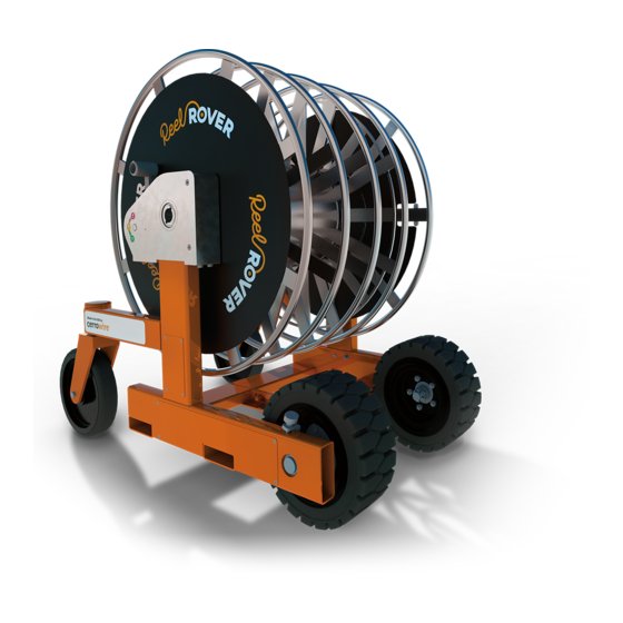
Page 6: Components
Components Each ReelRover has common components as shown below: Figure 1: ReelRover 3+1 (model RR-131136) Reel Options Three different reel versions are available, as shown in Figure 2: ▪ 1+1 – ground reel and a single, large conductor reel ▪ 3+1 – ground reel and conductor reel divided into three sections for three different wires... -
Page 7: Gps Unit
Figure 3: GPS Unit The devices are tied to a ReelRover via the IMEI number listed on the side of the unit. Users can request tracking for their unit by providing the IMEI number located on the GPS label. -
Page 8: Specifications
Wheel Base Width 32 inches Unloaded Vehicle Weight 700 lbs. Total Vehicle Capacity (vehicle + wire) 2700 lbs. Conductor Reel Capacity 1500 lbs. Ground Reel Capacity 500 lbs. Figure 4: ReelRover Specifications Side View Figure 5: ReelRover Specifications Top View... -
Page 9: Safety Procedures
▪ Do not drag, push, or tow ReelRover with another vehicle or device. ▪ Always keep hands on ReelRover while it is in motion. ▪ Do not stand or sit on any part of the ReelRover, or allow any person to stand, sit, or attempt to ride on the ReelRover. -
Page 10: Warnings
Warnings... -
Page 12: Gearbox Operation
The positions of the gearshift for each setting can be seen in Figures 7, 8, and 9. CAUTION: Do not shift gears when the ReelRover is in motion. Changing a gearbox setting while the machine is in motion will damage the gearbox. -
Page 13: Figure 7 Gearshift In Park
Figure 8: Gearshift in NEUTRAL DRIVE (D) Reel rotation drives the motion of the ReelRover in the same direction of reel rotation, either forwards or backwards Drive Wheel rotation is controlled by the speed and direction of reel rotation. Three rotations of... -
Page 14: Driving The Reelrover
When both gearboxes are placed in PARK, as shown in Figure 7, neither drive wheel will be able to rotate, effectively locking the ReelRover in position. The reel is still able to turn freely, allowing wire to be loaded or unloaded without the ReelRover moving. -
Page 15: Operating In Drive
The gear reduction allows for driving the ReelRover uphill, controlling the speed downhill, and going over obstacles. WARNING: Do not stand or sit on any part of the ReelRover, or allow any person to stand, sit, or attempt to ride on the ReelRover. -
Page 16: Steering In Drive
Steering in DRIVE When only one gearbox is placed in DRIVE, the ReelRover can be turned in the direction of the parked wheel. If the other gearbox is placed in PARK, the turn will be sharp (almost 90 degrees). Figure 13: Sharp Turn in DRIVE If the other gearbox is placed in NEUTRAL, the turn will be more gradual, depending on factors such as ground type and weight of wire on reel. -
Page 17: Figure 15 Caster Wheels Trail On Incline And Lead On Decline
Figure 15: Caster Wheels Trail on Incline and Lead on Decline WARNING: NEVER STAND OR WALK DIRECTLY BEHIND THE REELROVER ON AN INCLINE, AS SHOWN IN FIGURE 16. OPERATOR SHOULD WALK TO THE SIDE OF THE REELROVER. Figure 16: Never Stand or Walk Behind ReelRover on an Incline WARNING: NEVER TURN THE REELROVER ON AN INCLINE OR DECLINE. -
Page 18: Free-Spinning Ground Reel
Free-Spinning Ground Reel The ReelRover can be equipped with a free-spinning Ground Reel that can be locked or unlocked with the reel lock handle as shown in Figure 17. This allows for simultaneous loading and unloading of smaller gauge ground wire with the conductor wire, without the need for reel disassembly. -
Page 19: Lock The Free-Spinning Ground Reel
Lock the Free-Spinning Ground Reel The Free-Spinning Ground Reel should be rotationally locked to the Conductor Reel to load ground wire with conductor wire, and when operating ReelRover in DRIVE or NEUTRAL. NOTE: Ensure both gear selectors are placed in the PARK position. -
Page 20: Unlock The Free-Spinning Ground Reel
Once unlocked, the Free-Spinning Ground Reel is free to spin independently of the Conductor Reel for even payout of ground wire with conductor wires. NOTE: Ensure both ReelRover gear selectors are placed in the PARK position. 1: Pull plunger knob out so that Free-Spinning Ground Lock Handle may slide. -
Page 21: Wire Take-Up Process
The bolt visible in the ReelRover left gearbox hub, shown in Figure 21, secures the gearbox to the reel. It is possible for the bolt head to be damaged by the take-up adaptor if the ReelRover has suffered a separated gearbox-to-reel assembly. -
Page 22: Figure 22 Undamaged Securing Bolt Head
Figure 23, is an indicator of a separated gearbox-to-reel assembly. If any ReelRover is found with a damaged securing bolt, complete the ReelRover Lock-out Procedure and notify Cerrowire. The ReelRover must remain LOCKED-OUT until inspection and review by Cerrowire have been completed. Figure 23: Damaged Bolt Head... -
Page 23: Reelpower Stu Shaftless Take-Up Machine
ReelPower STU Shaftless Take-Up Machine To load wire onto the ReelRover with shaftless take-up equipment requires the use of right- and left-hand adaptors. Use the following procedure to safely load the ReelRover. WARNING: NEVER USE THE TAKE-UP EQUIPMENT AND ADAPTORS TO LIFT THE REELROVER AS IT MAY RESULT IN SERIOUS INJURIES. -
Page 24: Figure 26 Take-Up Adaptor Insertion (Left And Right Sides)
Figure 26: Take-up Adaptor Insertion (left and right sides) Position ReelRover Position ReelRover into the ReelPower STU shaftless take-up machine as shown in Figure 27, using either the DRIVE or NEUTRAL settings. Figure 27: Position ReelRover into the Shaftless Take-up Machine Align the centerline of the winding machine cone on each side with the centerline of the take-up adaptor’s... -
Page 25: Figure 28 Centerline Alignment Of Machine Cone With Outer Bore Of Take-Up Adaptor
Figure 28: Centerline Alignment of Machine Cone with Outer Bore of Take-up Adaptor Align the take-up machine’s engagement pin with the adaptor’s outer hole, as shown in Fig. 29 & 30. Figure 29: Align ReelRover and Take-up Machine Centerline and Drive Pin Figure 30: Align ReelRover Adaptors with Take-up Machine Cones... -
Page 26: Wemco 2800-Series Shafted Take-Up Machine
Once the ReelRover is in position and the take-up machine’s centerline is aligned with the ReelRover take-up adaptor, set both gearboxes to PARK as shown in Figure 31 to ensure that the ReelRover gearboxes are free spinning during loading of the wire onto the reel. -
Page 27: Figure 33 Insert Take-Up Adaptor
Remove Shaft and Insert Take-up Adaptor Remove the shaft from the take-up machine (Figure 32) according to the manufacturer’s instructions. Insert the take-up adaptor into the ReelRover’s left-side gearbox and take-up machine as shown in Figures 33 and 34. Figure 33: Insert Take-up Adaptor... -
Page 28: Figure 35 Align Take-Up Adaptor With Take-Up Machine Spindle Drive
Align the take-up machine’s centerline with the adaptor centerline as shown in Figure 35. Figure 35: Align Take-up Adaptor with Take-up Machine Spindle Drive Align the Wemco 2800 take-up machine’s drive pins on the shaft fitting with the mating holes of the take-up adaptor as shown in Figure 36. -
Page 29: Figure 37 Slide Spindle Drive Pins In Take-Up Adaptor Holes
Once the ReelRover is in position and the take-up machine’s centerline is aligned with the ReelRover take-up adaptor, set both gearboxes to PARK as shown in Figure 38 to ensure that the ReelRover gearboxes are free spinning during loading of the wire onto the reel. -
Page 30: Graham H8T20 Take-Up Machine
Graham H8T20 Take-up Machine This adaptor is a straight shaft, square drive adaptor which allows for the ReelRover to be loaded using the Graham H8T20 take-up machine. Figure 39: Graham H8T20 Take-up Machine NOTE: This adaptor was designed and tested on the Graham H8T20 unit and is not intended for, nor validated, on any other Graham H8T series equipment. -
Page 31: Wemco 2500 Take-Up Machine
Wemco 2500 Take-up Machine This adaptor (below left) is an offset gearbox which allows for the ReelRover to be loaded using the Wemco 2500 take-up machine. Figure 41: Wemco 2500 Take-up Machine and Adaptor CAUTION: FULLY REVIEW WEMCO 2500 AND REELROVER USER MANUALS PRIOR TO... -
Page 32: Figure 43 Engage The Motor
(Figure 45, right) Figure 45: Align ReelRover 9. Push the ReelRover fully into the take-up bay. Insert the caster locking pins and place both shift levers into the PARK position WARNING: DO NOT ENTER THE TAKE-UP BAY AT ANY TIME. -
Page 33: Figure 46 Align Shaft And Hub
12. Pull out the black knob and remove the retaining pin from the adapter output shaft 13. Guide the male connector into the female hub of the ReelRover (Figure 47) ▪ If misaligned, rotate the reel of the ReelRover until alignment is reached ▪... -
Page 34: Figure 49 Disengage The Adaptor
Figure 49: Disengage the Adaptor 3. Remove the wing nut from the threaded rod of the adapter mounting block (Figure 49, right) 4. Pull out black knob and insert retaining pin (Figure 50) Figure 50: Insert Retaining Pin 5. Lift adapter out of Wemco 2500... -
Page 35: Wire Unloading (Payout)
To unload wire from the ReelRover as shown in Figure 51, follow normal operating procedures to position the ReelRover in the desired location. Once in position, set both gearboxes to PARK, as shown in Figure 7, to ensure that the ReelRover will not move. -
Page 36: Transportation And Shipping
MACHINE IF LIFTED USING A STRAP OR CHAIN. Forklift Locations The ReelRover may be lifted from either side, and must only be lifted using a fork lift as shown in Figure 52. Do not attempt to lift the ReelRover by any other method. -
Page 37: Figure 53 Forks Correctly In Tubes
EXPERIENCE HORIZONTAL, VERTICAL, AND RADIAL MOVEMENT WHICH COULD LEAD TO LOSS OF BALANCE, LOSS OF CONTROL, AND DROPPING THE REELROVER. If the fork lift forks are positioned outside of the ReelRover fork tubes (Figure 54) the machine is liable to fall. -
Page 38: Secure Reelrover For Shipping
F.M.C.S.R. 393.100-114 “Protection Against Shifting and Falling Cargo.” Use this process for all models, with and without lull adaptor, to load and secure a ReelRover to a pallet for shipping. At least two bandings are required per pallet to ensure secure shipping. Use steel or poly banding as follows: 1. -
Page 39: Figure 56 Reelrover Into Truck
▪ The operator should stay inside the rear of the truck and not stand on the liftgate ▪ Use a spotter to ensure the ReelRover maintains a safe distance from all edges of the liftgate 6. Place both gearboxes in DRIVE (one gearbox at a time); remove forward chocks and/or straps 7. -
Page 40: Reelrover Lock-Out Procedure
A lock and key are stored in a box inside the User Manual Canister. The key cannot be removed unless the lock hasp is closed. When locked out the ReelRover cannot be moved or used until the machine has been serviced or repaired and the lock-out removed. To lock-out the ReelRover: 1. -
Page 41: Troubleshooting
▪ Call service line for further instructions ReelRover will not move in NEUTRAL. ▪ Check for and remove obstructions in front of any wheels, and see if ReelRover will move ▪ If this does not work, place both gearboxes in PARK ▪... -
Page 42: Equipment Inspection Prior To Use
The Equipment Inspection Checklist (located on the next page) should be completed by qualified personnel at the distributor prior to each time the ReelRover is loaded on a truck for delivery to the contractor. The ReelRover should only be delivered to the contractor once all inspection items have passed.