Cerrowire ReelRover User's Manual & Operating Instructions
Hide thumbs
Also See for ReelRover:
- User's manual & operating instructions (36 pages) ,
- Quick start manual (2 pages) ,
- User's manual and operating instructions (48 pages)
Table of Contents
Advertisement
Quick Links
Advertisement
Table of Contents

Related Manuals for Cerrowire ReelRover


Summary of Contents for Cerrowire ReelRover
- Page 1 ©2020 Cerrowire Rev 03/2020 A Marmon/Berkshire Hathaway Company...
- Page 2 Cerrowire to conduct training of distribution customers for proper use so that the ReelRover is safely and correctly operated in both the distribution facility and on the job site. Cerrowire provides the User Manual & Operating Instructions document to distribution customers so that subsequent internal training as well as external contractor training may be provided by the distributor.
-
Page 3: Table Of Contents
Steering in NEUTRAL ......................... 12 Operating the ReelRover in DRIVE .................... 13 Steering in DRIVE ........................14 Operating the ReelRover in DRIVE on a Ramp or Grade ............15 Ground Reel ..........................16 Ground Reel Lock Procedure ..................... 17 Ground Reel Unlock Procedure ....................18 Winding Adaptor ......................... -
Page 4: Figures
Figure 14: Winding Adaptor Insertion ....................19 Figure 15: Winding Device Centerline Location ................. 19 Figure 16a: Winding Device Use with ReelRover Winding Adaptor Aerial View and Detail ....20 Figure 16b: Winding Device Use with ReelRover Winding Adaptor ..........20 Figure 17a: NEUTRAL Gearshift Position .................. -
Page 5: Components
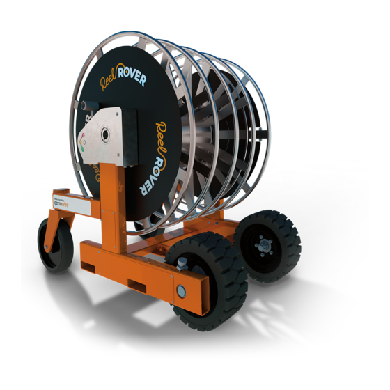
Components Figure 1a: ReelRover Components Figure 1b: Reel Components... -
Page 6: Specifications
32 inches Unloaded Vehicle Weight 700 lbs. Total Vehicle Capacity 2700 lbs. Conductor Reel Capacity 1500 lbs. Ground Reel Capacity 500 lbs. 65 in. Figure 2a: ReelRover Specifications Side View 60 in. 32 in. Figure 2b: ReelRover Specifications Aerial View... -
Page 7: Safety Procedures
Cerrowire or by ReelRover maintenance technicians/organizations. § Do not attempt to lift the ReelRover using a strap or chain. The ReelRover should only be lifted using a properly rated forklift or pallet jack in the locations shown in this manual. -
Page 8: Symbols And Warnings
Symbols and Warnings... -
Page 10: Gearbox
Gearbox The gearbox has three settings: PARK, NEUTRAL, and DRIVE. These settings control the rotation of the drive wheels and reel, as well as their relation to each other. The left and right gearboxes are independently set using the gearshift as shown in Figure 3. To change the setting, move the gearshift to the desired position (P, N, or D as labeled), making sure the spring detent positively locates in the corresponding hole. -
Page 11: Park (P)
(3) rotations of the reel is equal to approximately one (1) rotation of the drive wheels (3:1 gear ratio) Reel rotation drives the motion of the ReelRover in the same direction of reel rotation, either forwards or backwards Uses: o Controlling ReelRover down an... -
Page 12: Basic Operation
When both gearboxes are placed in PARK, as shown in Figure 4, neither drive wheel will be able to rotate, effectively locking the ReelRover in position. The reel is still able to turn freely, allowing wire to be loaded or unloaded without the ReelRover moving. -
Page 13: Operating The Reelrover In Drive
When both gearboxes are placed in DRIVE, as shown in Figure 6, the reel rotation is locked to the drive wheels with a gear reduction. The ReelRover can be driven either straight forward or back using the reel rotation. The gear reduction allows for driving the ReelRover uphill, controlling the speed downhill, and going over obstacles. -
Page 14: Steering In Drive
Steering in Drive When only one gearbox is placed in DRIVE, the ReelRover can be turned in the direction of the parked wheel. If the other gearbox is placed in PARK, the turn will be sharp (almost 90 degrees). If the other gearbox is placed in NEUTRAL, the turn will be more gradual, depending on factors such as ground type and weight of wire on reel. -
Page 15: Operating The Reelrover In Drive On A Ramp Or Grade
§ when operating on an incline, shown in Figure 10b. Never turn on a ramp or grade. Set the gearboxes and position the ReelRover on a flat § surface prior to using the grade so that ReelRover may move straight up or down the ramp or incline. -
Page 16: Ground Reel
Ground Reel The ReelRover can be equipped with a free-spinning Ground Reel that can be locked or unlocked with the reel lock handle as shown in Figure 11a. This allows for simultaneous loading and unloading of smaller gauge ground wire with the conductor wire, without the need for reel disassembly. -
Page 17: Ground Reel Lock Procedure
Ground Reel: Lock Procedure IMPORTANT: Make sure the ReelRover gear selectors (both sides) are placed in the PARK position. Step 1: Pull plunger knob out so that the Free-Spinning Ground Lock Handle may slide. Step 2: Slide the Free-Spinning Ground Lock Handle toward center of reel until the Position Indicator aligns with the Lock indicator. -
Page 18: Ground Reel Unlock Procedure
Ground Reel: Unlock Procedure IMPORTANT: Make sure the ReelRover gear selectors (both sides) are placed in the PARK position. Step 1: Pull plunger knob out so that Free-Spinning Ground Lock Handle may slide. Step 2: Slide the Free-Spinning Ground Lock Handle toward perimeter of reel until the Position Indicator aligns with the Unlock indicator. -
Page 19: Winding Adaptor
Figure Figure 14: Winding Adaptor Insertion Positioning ReelRover Position ReelRover, using either the DRIVE or NEUTRAL settings (see Fig. 17a & b), and operate the winding device as outlined in the manual for the specific device. -
Page 20: Winding Device Use With Reelrover
Figure 16a: Winding Device Use with ReelRover Winding Adaptor Aerial View and Detail Figure 16b: Winding Device Use with ReelRover Winding Adaptor... -
Page 21: Setting Gearbox
Once the ReelRover is in position and the winding device centerline is aligned with the ReelRover Winding Adaptor, make sure the ReelRover is on a level surface and set both gearboxes to NEUTRAL, as shown in Figure 17a, to ensure that the ReelRover gearboxes are free spinning during loading of the wire onto the reel. -
Page 22: Transportation & Shipping
The ReelRover should only be lifted using a forklift in the locations shown in Figure 19. This includes the forklift tubes on the sides of the ReelRover. To lift and transport the ReelRover using pallet a jack, position the forks of the pallet jack under the forklift tubes. -
Page 23: Using A Liftgate To Load The Reelrover
In order for a liftgate to be used to lift the ReelRover, it must be at least 84" x 60" and be rated for no less than 3000 lbs. If a liftgate does not meet these specifications, another method of loading must be used (i.e. -
Page 24: Using A Liftgate To Unload The Reelrover
In order for a liftgate to be used to lift the ReelRover, it must be at least 84" x 60" and be rated for no less than 3000 lbs. If a liftgate does not meet these specifications, another method of loading must be used (i.e. -
Page 25: Reelrover Lock-Out Procedure
If it has failed any of the check points on the Equipment Inspection Checklist. Position the ReelRover on a level surface and place both gear selectors in the PARK (P) position if possible. Remove the wire cable and lock from the black plastic canister attached to the lower frame of the ReelRover located behind one of the drive wheels. -
Page 26: Troubleshooting
If this does not solve locked reel, place both gearboxes in Park and call service line for further instructions. § ReelRover will not move in NEUTRAL. Check for obstruction in front of any wheels and remove if found. See if ReelRover can now be moved. If this does not work, place both gearboxes in PARK. -
Page 27: Equipment Inspection Prior To Use
The Equipment Inspection Checklist (located on page 28 of this document) should be completed by qualified personnel at the distributor prior to each time the ReelRover is loaded on a truck for delivery to the contractor. The ReelRover should only be delivered to the contractor once it has passed all of the designated inspection items. -
Page 28: Equipment Inspection Checklist
Fail Notes Initials Both gearshifts freely move into all three positions (P/N/D) ReelRover freely moves when pushed manually while both gearshifts are in the NEUTRAL (N) position Gearboxes Both drive wheels are intact and rotate on the axle while the gearshift is in DRIVE Both caster wheels swivel 360°... -
Page 29: Figure 23: Left-Hand 180° Driven Turn
Figure 23: Left-Hand 180° Driven Turn Test 1 Left-Hand 180° Driven Turn with Right-Hand Gearbox in DRIVE, Left-Hand Gearbox in PARK Parked wheel rotates about AXIS (noted by amber crosshair), but does not rotate about axle. AXIS Correct Forward Movement Correct Backward Movement... -
Page 30: Figure 24: Right-Hand 180° Driven Turn
Figure 24: Right-Hand 180° Driven Turn Test 2 Right-Hand 180° Driven Turn with Right-Hand Gearbox in PARK, Left-Hand Gearbox in DRIVE Parked wheel rotates about AXIS (noted by amber crosshair), but does not rotate about axle. AXIS Correct Forward Movement Correct Backward Movement...