Cerrowire ReelRover User's Manual & Operating Instructions
Wire loading estimator
Hide thumbs
Also See for ReelRover:
- User's manual & operating instructions (30 pages) ,
- Quick start manual (2 pages) ,
- User's manual and operating instructions (48 pages)

Related Manuals for Cerrowire ReelRover


Summary of Contents for Cerrowire ReelRover
- Page 1 For use with ReelRover Serial Numbers 36X-20-01-0001-XXX to 36X-2012-0017-XXX Page 1 of 36 ©2020 Cerrowire Rev 07/16/2020 A Marmon/Berkshire Hathaway Company...
- Page 2 Cerrowire to conduct training of distribution customers for proper use so that the ReelRover is safely and correctly operated in both the distribution facility and on the job site. Cerrowire provides the User Manual & Operating Instructions document to distribution customers so that subsequent internal training as well as external contractor training may be provided by the distributor.
-
Page 3: Table Of Contents
Steering in NEUTRAL ..................... 13 Operating the ReelRover in DRIVE ................14 Steering in DRIVE ......................15 Operating the ReelRover in DRIVE on an Incline or Decline Surface ......16 Ground Reel ..........................17 Free-Spinning Ground Reel: Lock Procedure ..............18 Free-Spinning Ground Reel: Unlock Procedure ............... -
Page 4: Figures
Figure 14b: Winding Adaptor Insertion ..................... 20 Figure 14c: Opposite-side Adaptor ....................20 Figure 15a: Positioning of the ReelRover into the Shaftless Take-up Machine ........ 21 Figure 15b: Shaftless Take-up Machine Use with ReelRover Winding Adaptor ....... 21 Figure 15c: Centerline Alignment of Machine Cone with Outer Bore of Winding Adaptor ....22 Figure 15d: Centerline Alignment Between ReelRover and Take-up Machine and Alignment of the Pin with the Adaptor ...................... - Page 5 Figure 20c: Insert Locking Pin ......................29 Figure 20d: Moving ReelRover into Truck ..................29 Figure 21a: Moving ReelRover off Truck onto Liftgate ..............30 Figure 21b: Remove Locking Pin ...................... 30 Figure 21c: Insert Locking Pin ......................30 Figure 21d: Moving ReelRover Off Liftgate ..................30 Figure 22a: Removal of Wire Cable and Lock from Canister ............
-
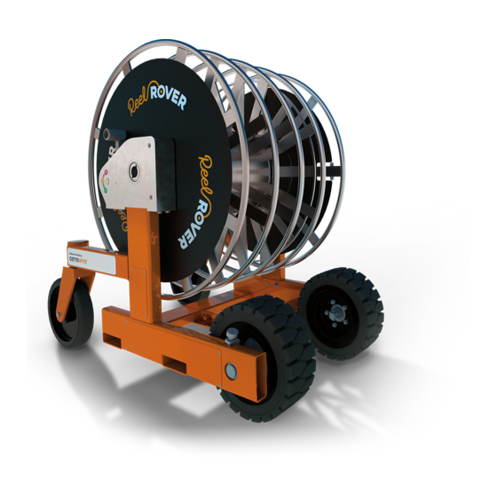
Page 6: Components
Components Figure 1a: ReelRover 3+1 (model RR-131136) Figure 1b: ReelRover 1+1 (model RR-111136) Page 6 of 36... -
Page 7: Specifications
32 inches Unloaded Vehicle Weight 700 lbs. Total Vehicle Capacity (vehicle + wire) 2700 lbs. Conductor Reel Capacity 1500 lbs. Ground Reel Capacity 500 lbs. Figure 2a: ReelRover Specifications Side View Figure 2b: ReelRover Specifications Top View Page 7 of 36... -
Page 8: Safety Procedures
Do not modify the ReelRover in any way. Do not use the ReelRover in any application other than that for which it was designed. If you have any questions relative to a particular application, DO NOT use the ReelRover until you have first contacted Cerrowire to determine if that application is appropriate for the ReelRover. -
Page 9: Symbols And Warnings
Symbols and Warnings Page 9 of 36... - Page 10 Page 10 of 36...
-
Page 11: Gearbox
To change the setting, move the gearshift to the desired position (P, N, or D as labeled), making sure the spring detent positively locates in the corresponding hole. The positions of the gearshift for each setting can be seen in Figures 4 through 6. Do not shift with ReelRover in motion. Figure 3: Gearbox Settings... -
Page 12: Park (P)
(1) rotation of the drive wheels (3:1 gear ratio) Reel rotation drives the motion of the ReelRover in the same direction of reel rotation, either forwards or backwards Uses: Controlling ReelRover down an incline... -
Page 13: Basic Operation
When both gearboxes are placed in PARK, as shown in Figure 4, neither drive wheel will be able to rotate, effectively locking the ReelRover in position. The reel is still able to turn freely, allowing wire to be loaded or unloaded without the ReelRover moving. -
Page 14: Operating The Reelrover In Drive
When both gearboxes are placed in DRIVE, as shown in Figure 8, the reel rotation is locked to the drive wheels with a gear reduction. The ReelRover can be driven either straight forward or back using the reel rotation. The gear reduction allows for driving the ReelRover uphill, controlling the speed downhill, and going over obstacles. -
Page 15: Steering In Drive
Steering in Drive When only one gearbox is placed in DRIVE, the ReelRover can be turned in the direction of the parked wheel. If the other gearbox is placed in PARK, the turn will be sharp (almost 90 degrees). If the other gearbox is placed in NEUTRAL, the turn will be more gradual, depending on factors such as ground type and weight of wire on reel. -
Page 16: Operating The Reelrover In Drive On An Incline Or Decline Surface
Figure 10b. Never turn on an incline or decline. Set the gearboxes and position the ReelRover on a flat surface prior to using a ramp so that ReelRover may move straight up or down a ramp. Never stand or walk directly behind the ReelRover on an incline, Figure 10a. -
Page 17: Ground Reel
Free-Spinning Ground Reel The ReelRover can be equipped with a free-spinning Ground Reel that can be locked or unlocked with the reel lock handle as shown in Figure 11a. This allows for simultaneous loading and unloading of smaller gauge ground wire with the conductor wire, without the need for reel disassembly. -
Page 18: Free-Spinning Ground Reel: Lock Procedure
Free-Spinning Ground Reel: Lock Procedure IMPORTANT: Make sure the ReelRover gear selectors (both sides) are placed in the PARK position. Step 1: Pull plunger knob out so that the Free-Spinning Ground Lock Handle may slide. Step 2: Slide the Free-Spinning Ground Lock Handle toward center of reel until the Position Indicator aligns with the Lock indicator. -
Page 19: Free-Spinning Ground Reel: Unlock Procedure
Free-Spinning Ground Reel: Unlock Procedure IMPORTANT: Make sure the ReelRover gear selectors (both sides) are placed in the PARK position. Step 1: Pull plunger knob out so that Free-Spinning Ground Lock Handle may slide. Step 2: Slide the Free-Spinning Ground Lock Handle toward perimeter of reel until the Position Indicator aligns with the Unlock indicator. -
Page 20: Wire Take-Up Process
Wire Take-up Process Winding Adaptor – Shaftless Equipment In loading wire onto the ReelRover, certain shaftless take-up equipment may be used whereby right- & left-hand adaptors must be utilized. Use the following procedure for safely operating the take-up equipment to load the ReelRover. NEVER USE THE TAKE-UP EQUIPMENT AND ADAPTORS TO LIFT THE REELROVER AS IT MAY RESULT IN SERIOUS INJURIES. -
Page 21: Positioning Reelrover
Positioning ReelRover Position ReelRover into the shaftless take-up machine, Figures 15a and 15b, using either the DRIVE or NEUTRAL settings. Figure 15a: Positioning of the ReelRover into the Shaftless Take-up Machine Figure 15b: Shafltess Take-up Machine Use with ReelRover Winding Adaptor... -
Page 22: Figure 15C: Centerline Alignment Of Machine Cone With Outer Bore Of Winding Adaptor
Figures 15d and 15e and the engagement pins adjusted to fit into the outer holes of the adaptor. Figure 15d: Centerline Alignment Between ReelRover and Take-up Machine and Alignment of the Pin with the Adaptor Figure 15e: ReelRover Adaptors Alignment with Machine’s Cones... -
Page 23: Setting The Gearbox
Setting the Gearbox Once the ReelRover is in position and the take-up machine’s centerline is aligned with the ReelRover Winding Adaptor, make sure the ReelRover is on a level surface and set both gearboxes to PARK as shown in Figure 16 to ensure that the ReelRover gearboxes are free spinning during loading of the wire onto the reel. -
Page 24: Winding Adaptor - Shafted Equipment
Winding Adaptor – Shafted Equipment In loading wire onto the ReelRover, certain shafted take-up equipment may be used whereby the shaft must be removed and a left-hand adaptor must be utilized. Use the following procedure for safely operating the take-up equipment to load the ReelRover. NEVER USE THE TAKE-UP EQUIPMENT AND ADAPTOR TO LIFT THE REELROVER AS IT MAY RESULT IN SERIOUS INJURIES. -
Page 25: Positioning Reelrover In The Take-Up Machine
Positioning ReelRover in the Take-up Machine Position the ReelRover using either the NEUTRAL or DRIVE settings, as shown in Figures 17c and 17d, into the take-up machine. Figure 17d: ReelRover Gearbox Figure 17c: Positioning of ReelRover into Take-up Machine with Shaft Removed... -
Page 26: Figure 17E: Aligning The Winding Adaptor With The Take-Up Machine Spindle Drive
Align the take-up machine’s centerline with the centerline of the adaptor as shown in Figure 17e. Figure 17e: Aligning the Winding Adaptor with the Take-up Machine Spindle Drive The machine’s drive pins on the shaft fitting should line up with the mating holes of the winding adaptor as shown in Figure 17f. -
Page 27: Setting The Gearbox
2700 lbs. Wire Unloading (Payout) To unload wire from the ReelRover as shown in Figure 18b, position the ReelRover in the desired location, following the normal operation instructions. Once in position, set both gearboxes to PARK, as shown in Figure 18a, to ensure that the ReelRover will not move. -
Page 28: Transportation & Shipping
The center of mass of the ReelRover should always be assumed to be the centerline of the reel; however, the center of gravity of the ReelRover will vary according to the wire and how it is loaded on to the ReelRover. This must be taken into consideration when the ReelRover is moved, loaded and unloaded on to and off of a vehicle and while being transported. -
Page 29: Using A Liftgate To Load The Reelrover
In order for a liftgate to be used to lift the ReelRover, it must be at least 84" x 60" and be rated for a minimum of 3000 lbs. If the liftgate does not meet these specifications, another method of loading must be used (i.e. -
Page 30: Using A Liftgate To Unload The Reelrover
In order for a liftgate to be used to lift the ReelRover, it must be at least 84" x 60" and be rated for a minimum of 3000 lbs. If the liftgate does not meet these specifications, another method of loading must be used (i.e. -
Page 31: Reelrover Lock-Out Procedure
ReelRover Lock-out Procedure The following lock-out procedure is to be used to lock-out the ReelRover into a safe state for storage or repair. Do not operate the ReelRover if any of the conditions below exist: If troubleshooting procedures have failed to correct a problem with the ReelRover. -
Page 32: Troubleshooting
Call service line for further instructions. ! ReelRover will not move in NEUTRAL. Check for obstruction in front of any wheels and remove if found. See if ReelRover can now be moved. If this does not work, place both gearboxes in PARK. -
Page 33: Equipment Inspection Prior To Use
The Equipment Inspection Checklist (located on page 34 of this document) should be completed by qualified personnel at the distributor prior to each time the ReelRover is loaded on a truck for delivery to the contractor. The ReelRover should only be delivered to the contractor once it has passed all of the designated inspection items. -
Page 34: Equipment Inspection Checklist
Fail Notes Initials Both gearshifts freely move into all three positions (P/N/D) ReelRover freely moves when pushed manually while both gearshifts are in the NEUTRAL (N) position Gearboxes Both drive wheels are intact and rotate on the axle while the gearshift is in DRIVE Both caster wheels swivel 360°... -
Page 35: Figure 23: Left-Hand 180° Driven Turn
Figure 23: Left-Hand 180° Driven Turn Test 1 Left-Hand 180° Driven Turn with Right-Hand Gearbox in DRIVE, Left-Hand Gearbox in PARK Parked wheel rotates about AXIS (noted by amber crosshair), but does not rotate about axle. AXIS Correct Forward Movement Correct Backward Movement 35 of 36... -
Page 36: Figure 24: Right-Hand 180° Driven Turn
Figure 24: Right-Hand 180° Driven Turn Test 2 Right-Hand 180° Driven Turn with Right-Hand Gearbox in PARK, Left-Hand Gearbox in DRIVE Parked wheel rotates about AXIS (noted by amber crosshair), but does not rotate about axle. AXIS Correct Forward Movement Correct Backward Movement 36 of 36...