Advertisement
Quick Links
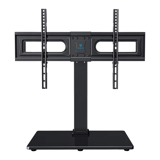
Table Top TV Stand Instruction
Website:
www.perlesmith.com
Manual
Model: PSTVS18
Thank you for choosing this PERLESMITH product! At PERLESMITH we
strive to provide you with the best quality products and services in the
industry. Please share your experience of our product with others at
www.perlesmith.com/pages/reviews if you are satisfied. Should you have
any issues, please don't hesitate to contact us.
Technical Support:
1-800-556-6806 Mon-Fri 10am - 5pm (PST) (USA) (CAN)
Other Info:
supportus@perlesmith.com (US)
supportca@perlesmith.com (CA)
V1.0
Advertisement

Related Manuals for Perlesmith PSTVS18


Summary of Contents for Perlesmith PSTVS18
- Page 1 Manual V1.0 Model: PSTVS18 Thank you for choosing this PERLESMITH product! At PERLESMITH we strive to provide you with the best quality products and services in the industry. Please share your experience of our product with others at www.perlesmith.com/pages/reviews if you are satisfied. Should you have any issues, please don't hesitate to contact us.
- Page 2 If your TV VESA is greater than 600x400 mm/24x16 in. or less than VESA 200x100mm/8x4in., this TV stand is NOT compatible. If this TV stand is NOT compatible, please contact customer service at supportus@perlesmith.com (US)/ supportca@perlesmith.com (CA) to find a compatible product. Tools Needed (Not lncluded)
- Page 3 Before starting assembly, verify all parts are included and undamaged. Do not use damaged or defective parts. lf you require replacement parts, contact our Product Support line at 1-800-556-6806 or customer service at supportus@perlesmith.com (US)/ supportca@perlesmith.com (CA). • Please note: Not all hardware included in this package will be used.
- Page 4 Supplied Part and Hardware for Step 3 Note: The bolt is shown in accordance with the actual size (H) x1 5/32in. (4mm) TV Plate TV Plate Allen Key Connector Supplied Parts and Hardware for Step 4 TV Bracket Note: The bolts and spacers are shown in accordance with the actual size (M-A) x4 (M-B) x4 (M-C) x4...
- Page 5 Supplied Part for Step 5 (F) x2 Safety Lock Step 1 Assemble the Base Place rubber feet [A] to the tempered glass base [01] in the Step 1-1 corners Note: Kindly note that the tempered glass base is designed to show the shiny glass side facing up Step 1-2 Connect the lower support pillar [02] to tempered glass base [01]...
- Page 6 Step 2 Connect the Upper Support Pillar [03] to Lower Support Pillar [02] Step 3 Connect the TV Plates [05] to Upper Support Pillar [03] Note: There are two choices for height adjustment. You can choose your desired height position while connecting the TV plates [05] to upper support pillar [03] The First Choice The Second Choice...
- Page 7 Please do not firmly tighten the 4pcs bolts [E] in this step. Insert the other TV plate into the TV plate connector, then insert the other 4pcs bolts [E] into the TV plate. Finally secure the TV plates to upper support pillar by tightening the 8pcs bolts [E]...
- Page 8 (meaning stacked). If you have any difficulty understand- ing how to install the TV bolts or spacers, please contact customer service at supportus@perlesmith.com (US)/ supportca@perlesmith.com (CA). CAUTION: Ensure the TV brackets [06] is EQUALLY CENTERED on your TV and securely fastened in place.
- Page 9 Option A (For Flat Back TV) The spacers must be used with washers [M-G] to stop spacers from falling down. M-A/M-C M-I(If needed) Note: Keep the arrow up Option B (For Round Back TV) The spacers must be used with washers [M-G] to stop spacers from falling down. M-B/M-D/M-E M-H/M-I Alternate Spacer...
- Page 10 Option C (For TV with A “Bump”) Spacers may be necessary for 2 holes ONLY. The spacers must be used with washers [M-G] to stop spacers from falling down. M-B/M-D/M-E M-A/M-C M-H/M-I Alternate Spacer Setups Note: Keep the arrow up Option D For cable interference or inset holes, use spacers [M-H] and [M-I] to create extra space between the TV and TV brackets.
- Page 11 Step 5 Secure TV to TV Plate and Manage the Wires TV brackets are three-height-adjustable. You can choose the proper height. The First Choice The Second Choice The Third Choice Step 5-1 Hang the TV with brackets to the TV plate Step 5-2 Push the bottom of the TV to TV plate Step 5-3 Insert the safety locks [F] into the upward facing hooks at the midway to lower part of the TV bracket.
- Page 12 Step 6 Adjust Swivel Angle of TV Stand If necessary,the TV plate or TV can be swivelled manually.
Need help?
Do you have a question about the PSTVS18 and is the answer not in the manual?
Questions and answers