Table of Contents
Advertisement
Quick Links
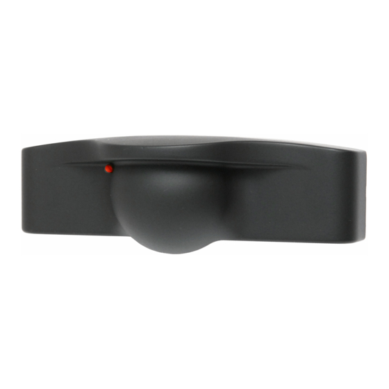
DESCRIPTION
The microStar™ is a microwave motion sensor with Human
Presence Radar™ (HPR™) for activating all types of
automatic doors. The sensor is capable of wide or narrow
detection patterns and provides a relay output for simple
interfacing with a door controller or other type of device.
INCLUDED IN THE BOX
(1) microStar™ Motion Sensor
(1) Wire Harness
(2) Mounting Screws
(1) Installation Instructions
SPECIFICATIONS
Model
Input Power
Power Consumption
Output Contacts
Output Hold Time
Temperature Rating
Weight
Microwave Frequency
Max. Mounting Height
Color
Material
Compliances
MECHANICAL INSTALLATION
NOTE: Remember to follow these safety precautions:
Shut off power to the automatic door before wiring sensor.
Always ensure wiring is located clear of any moving door parts to avoid damage.
Always be aware of pedestrian traffic. Keep people clear of the work area when setting up or testing the door.
Comply with all applicable building codes and safety standards (ANSI A156.10).
Page 1 of 6
microStar™ Motion Sensor
microStar™
12-24V AC/DC +/-10 %
3.5W Maximum
Form C, Rated at 1 Amp
Max. 5 Seconds
-22°F to 158°F (-30°C to 70°C)
<1 lb.
24.125 GHz +/- 50 MHz
15' (4.6M)
Flat Black Cover
ABS Plastic Cover & Base
FCC Part 15
DIMENSIONS
microStar 032021-V1
Advertisement
Table of Contents

Related Manuals for MS Sedco microStar


Summary of Contents for MS Sedco microStar
- Page 1 Motion Sensor DESCRIPTION The microStar™ is a microwave motion sensor with Human Presence Radar™ (HPR™) for activating all types of automatic doors. The sensor is capable of wide or narrow detection patterns and provides a relay output for simple interfacing with a door controller or other type of device.
- Page 2 ① Remove the sensor cover: Remove the cover of the microStar by placing the blade of a small screwdriver in the notch in the right side of the cover as shown at right. Once the sensor is attached to the header the cover can be removed in this same manner.
- Page 3 DIPSWITCH SETTINGS LEFT 6. NOT USED 6. NOT USED 5. FAIL-SAFE OFF 5. FAIL-SAFE ON 4. HPR OFF 4. HPR ON 3. NOT USED 3. NOT USED 2. DEPART 2. APPROACH 1. BI-DIRECTIONAL 1. UNI-DIRECTIONAL Page 3 of 6 microStar 032021-V1...
- Page 4 ① Upon completion of the mechanical installation, configuring the sensor, and all necessary wiring, apply voltage to the sensor (12 to 24 volts AC or DC). The LED located at the lower left side of the antenna will illuminate green when the sensor is ready for use. Page 4 of 6 microStar 032021-V1...
- Page 5 Simply watch the LED while approaching the pattern Green = No detection; Red = Detection. Once the desired pattern is achieved press the reset button and the microStar will reset to normal operating mode. RE-INSTALL COVER ①...
- Page 6 QUALIFIED INSTALLERS When applying this product to an automatic pedestrian door, MS Sedco recommends this product only be installed by technicians who are certified inspectors by the American Association of Automatic Door Manufacturers. All installations shall be compliant to applicable nationally recognized performance standards.
Need help?
Do you have a question about the microStar and is the answer not in the manual?
Questions and answers